ETSI TS 102 220
V1.1.1
(2004-04)
Technical Specification
Access and Terminals (AT);
Technical Specification: Delivery of Cable based services
across a home access to the devices in the home
Reference DTS/AT-000003
Keywords
access, broadband, e-commerce, intelligent homes & buildings
ETSI
650 Route des Lucioles
F-06921 Sophia Antipolis Cedex - FRANCE Tel.: +33 4 92 94 42 00 Fax: +33 4 93 65 47 16
Siret N° 348 623 562 00017 - NAF 742 C Association à but non lucratif enregistrée à la
Sous-Préfecture de Grasse (06) N° 7803/88
Important notice
Individual copies of the present document can be downloaded from:
http://www.etsi.org
The present document may be made available in more than one electronic version or in print. In any case of existing or perceived difference in contents between such versions, the reference version is the Portable Document Format (PDF). In case of dispute, the reference shall be the printing on ETSI printers of the PDF version kept on a specific network drive
within ETSI Secretariat.
Users of the present document should be aware that the document may be subject to revision or change of status. Information on the current status of this and other ETSI documents is available at
http://portal.etsi.org/tb/status/status.asp
If you find errors in the present document, send your comment to:
Copyright Notification
No part may be reproduced except as authorized by written permission. The copyright and the foregoing restriction extend to reproduction in all media.
© European Telecommunications Standards Institute 2004. All rights reserved.
DECTTM, PLUGTESTSTM and UMTSTM are Trade Marks of ETSI registered for the benefit of its Members.
TIPHONTM and the TIPHON logo are Trade Marks currently being registered by ETSI for the benefit of its Members.
Contents
Intellectual Property Rights ...8
Foreword...8
Introduction ...8
1 Scope ...10
2 References ...10
3
Definitions, abbreviations and conventions ...13
3.1 Definitions ...13 3.2 Abbreviations ...13 3.3 Conventions...15
4 Overview ...15
4.1 Assumptions ...155 Reference
architecture...16
5.1 Logical reference architecture ...17
5.1.1 Cable2Home domains...17
5.1.2 Logical elements ...18
5.1.2.1 Portal Services (PS)...18
5.1.3 Device classes ...18
5.1.3.1 Embedded PS and standalone PS ...18
5.1.4 Address Realms ...19
5.2 Cable2Home functional reference model ...20
5.2.1 Cable2Home management functions ...20
5.2.2 Cable2Home security functions ...22
5.2.3 Cable2Home QoS functions ...23
5.3 Cable2Home messaging interface model ...23
5.4 Cable2Home information reference model ...24
5.5 Cable2Home operational models ...26
5.6 Cable2Home physical interfaces ...27
6 Management
tools ...28
6.1 Introduction/overview ...28
6.1.1 Goals ...28
6.1.2 Assumptions ...28
6.2 Management architecture ...28
6.2.1 System design guidelines...28
6.2.2 Management tools system description ...29
6.3 The Cable2Home Management Portal (CMP) ...30
6.3.1 CMP goals ...30
6.3.2 CMP design guidelines ...30
6.3.3 CMP system description ...31
6.3.4 General CMP requirements...33
6.3.5 SNMP protocol requirements ...35
6.3.6 Network management mode requirements ...35
6.3.6.1 Network management modes for a PS operating in DHCP provisioning mode...35
6.3.6.1.1 Basic operation for a PS operating in DHCP provisioning mode...35
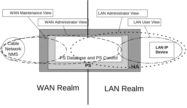
6.3.6.2 Network management mode for a PS operating in SNMP provisioning mode ...37
6.3.6.2.1 Management views ...37
6.3.6.2.2 WAN-access control...39
6.3.6.2.3 Security...39
6.3.6.3 View-based access control model (VACM) requirements ...39
6.3.7 Cable2Home MIB requirements ...40
6.3.8 Interfaces Group MIB requirements ...41
6.4.1 CTP goals ...42
6.4.2 CTP design guidelines ...43
6.4.3 CTP system description ...43
6.4.3.1 CTP connection speed tool...43
6.4.3.2 CTP ping tool ...43
6.4.4 CTP requirements ...44
6.4.4.1 Connection speed tool ...44
6.4.4.2 Ping tool ...45
6.5 Event reporting ...46
6.5.1 Event notification...46
6.5.1.1 Local event logging...47
6.5.1.2 SNMP TRAP and INFORM ...48
6.5.1.3 SYSLOG ...48
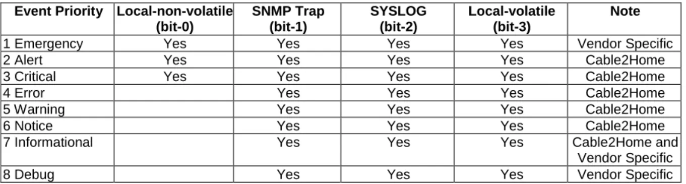
6.5.2 Format of events ...49
6.5.2.1 Event priorities ...49
6.5.2.2 Standard events ...50
6.5.3 Event throttling and limiting ...51
6.5.4 Secure software download event reporting ...51
7 Provisioning
tools...51
7.1 Introduction/overview ...51 7.1.1 Provisioning modes...51 7.1.2 Provisioning architecture ...52 7.1.3 Goals ...52 7.1.4 Assumptions ...537.2 Cable2Home DHCP portal architecture ...53
7.2.1 Cable2Home DHCP portal system design guidelines...53
7.2.2 Cable2Home DHCP portal system description...54
7.2.2.1 CDS system description ...55
7.2.2.2 CDC system description...57
7.2.2.2.1 Cable2Home DHCP client option 61 ...57
7.2.2.2.2 WAN address modes ...57
7.2.3 Cable2Home DHCP portal requirements...59
7.2.3.1 CDP requirements ...59
7.2.3.2 CDS requirements ...60
7.2.3.3 CDC requirements...62
7.3 Bulk portal services configuration architecture ...67
7.3.1 Bulk portal services configuration system design guidelines ...67
7.3.2 Bulk portal services configuration system description ...67
7.3.3 Bulk portal services configuration requirements ...68
7.3.3.1 Configuration file format requirements...68
7.3.3.1.1 Pad configuration setting ...69
7.3.3.1.2 Software upgrade filename ...69
7.3.3.1.3 SNMP write-access control ...69
7.3.3.1.4 Software upgrade TFTP server...69
7.3.3.1.5 SNMP MIB object with extended length...69
7.3.3.1.6 Manufacturer code verification certificate...70
7.3.3.1.7 Co-signer code verification certificate...70
7.3.3.1.8 SNMPv3 kickstart value ...70
7.3.3.1.9 Configuration file element - docsisV3Notification receiver...71
7.3.3.1.10 End-of-data marker...72
7.3.3.1.11 PS Message Integrity Check (PS MIC) ...72
7.3.3.2 Mode of Triggering ...73
7.3.3.3 Means of authenticating the PS configuration file ...74
7.3.3.3.1 PS configuration file authentication algorithm for DHCP provisioning mode...74
7.3.3.3.2 Configuration file authentication algorithm for SNMP provisioning mode ...75
7.3.3.4 Means of reporting status ...75
7.4 Time of day client architecture...77
7.4.1 Time of day client system design guidelines ...77
7.4.2 Time of day client system description ...77
8
Packet handling and address translation...79
8.1 Introduction/overview ...79
8.1.1 Goals ...79
8.1.2 Assumptions ...79
8.2 Architecture ...79
8.2.1 System design guidelines...79
8.2.2 Packet handling system description ...79
8.2.2.1 Packet handling functional overview ...80
8.2.2.2 Packet handling modes...81
8.2.2.3 Upstream selective forwarding switch overview ...83
8.2.2.4 Multicast ...84
8.2.2.5 Cable2Home packet handling examples ...85
8.3 CAP requirements ...86
8.3.1 General requirements ...86
8.3.2 Packet handling requirements ...87
8.3.2.1 Passthrough requirements ...87
8.3.2.2 C-NAT and C-NAPT transparent routing requirements...87
8.3.2.3 Mixed bridging/routing mode requirements...88
8.3.3 USFS requirements ...88
9 Name
resolution ...88
9.1 Introduction/overview ...88 9.1.1 Goals ...88 9.1.2 Assumptions ...89 9.2 Architecture ...899.2.1 System design guidelines...89
9.2.2 System description...89
9.2.2.1 Name resolution functional overview ...89
9.2.2.2 Name resolution operation ...89
9.3 Name resolution requirements...91
10
Quality of Service (QoS)...91
10.1 Introduction ...91
10.1.1 Goals ...92
10.1.2 Assumptions ...92
10.2 QoS architecture ...92
10.2.1 System design guidelines...92
10.2.2 Cable2Home QoS system description...92
10.2.2.1 Element - portal services ...93
10.2.2.1.1 CQP component...93
10.2.2.1.2 Standalone PS configuration ...93
10.2.2.2 CQoS domain ...93
10.2.2.3 Physical device classes and CQoS functional elements ...93
10.3 Cable2Home QOS messaging requirements ...94
10.3.1 CQP requirements...94
10.3.2 QoS Policy management and admission control...94
11 Security...94
11.1 Introduction/overview ...94
11.1.1 Goals ...95
11.1.2 Assumptions ...95
11.2 Security architecture...95
11.2.1 System design guidelines...95
11.2.2 System description...96
11.2.2.1 Security domain ...97
11.2.2.2 PS function - Portal Services...97
11.2.3 Key Distribution Center (KDC) server ...99
11.2.4 Other related Cable2Home elements and functions...99
11.3 Requirements...99
11.3.1 Element authentication ...99
11.3.2 Cable2Home Public Key Infrastructure (PKI)...101
11.3.2.1 Generic structure ...101
11.3.2.1.1 Version ...101
11.3.2.1.2 Public key type ...101
11.3.2.1.3 Extensions ...101
11.3.2.1.4 Signature algorithm ...102
11.3.2.1.5 SubjectName and IssuerName...102
11.3.2.1.6 serialNumber ...102
11.3.2.2 Certificate hierarchies ...102
11.3.2.2.1 Manufacturer certificate hierarchy ...103
11.3.2.2.2 Code Verification Certificate hierarchy...105
11.3.2.2.3 Service Provider Certificate Hierarchy...107
11.3.2.3 Certificate validation ...110
11.3.2.3.1 Validation for the manufacturer chain and root verification...110
11.3.2.3.2 Validation for the code verification chain and root verification ...110
11.3.2.3.3 Validation for the service provider chain and root verification ...110
11.3.2.4 Certificate revocation ...110
11.3.3 Secure management messaging ...111
11.3.3.1 Security algorithms for SNMP in DHCP provisioning mode ...111
11.3.3.1.1 NmAccess mode ...111
11.3.3.1.2 CoexistenceMode ...111
11.3.3.2 Security algorithms for SNMPv3 in SNMP provisioning mode ...114
11.3.3.2.1 SNMPv3 encryption algorithms ...114
11.3.3.2.2 SNMPv3 authenticationalgorithms...114
11.3.3.2.3 Kerberized SNMPv3 ...114
11.3.3.2.4 SNMPv3 Engine IDs ...114
11.3.3.2.5 Populating the usmUserTable...115
11.3.4 Secure CQoS...115
11.3.4.1 CQoS architecture ...115
11.3.4.2 IPCablecom secured DQoS architecture ...116
11.3.4.3 CQoS security architecture ...116
11.3.4.4 The Role of the CSP in CQoS ...117
11.3.5 Firewall management...117
11.3.5.1 Remote download of CH firewall rule set...118
11.3.5.2 Firewall rule set management parameters ...119
11.3.5.3 Firewall event log...119
11.3.5.4 Management parameters for event logging ...120
11.3.6 MIBs ...120
11.3.7 Secure software download ...121
11.3.7.1 Software download into embedded or standalone PS elements ...123
11.3.7.2 Code file requirements ...123
11.3.7.2.1 Code download file structure for secure software download...123
11.3.7.3 Code Verification Certificate (CVC) format ...126
11.3.7.3.1 CVC format for secure software download ...126
11.3.7.3.2 Certificate revocation ...127
11.3.7.4 Code file access controls ...127
11.3.7.4.1 Subject organization names ...127
11.3.7.4.2 Time varying controls...128
11.3.7.5 Code upgrade initialization ...128
11.3.7.5.1 Manufacturer initialization ...128
11.3.7.5.2 Network initialization ...129
11.3.7.6 CVC processing ...130
11.3.7.6.1 Processing the configuration file CVC ...130
11.3.7.6.2 Processing the SNMP CVC ...131
11.3.7.7 Code signing requirements...131
11.3.7.7.1 Certificate Authority (CA) requirements...131
11.3.7.8 Triggering process...132
11.3.7.8.1 SNMP-initiated software download ...132
11.3.7.8.2 Configuration-file-initiated software download ...134
11.3.7.9 Code verification...135
11.3.8 Physical security ...138 11.3.9 Cryptographic algorithms ...138 11.3.9.1 SHA-1 ...138
12 Management
processes...139
12.1 Introduction/overview ...139 12.1.1 Goals ...13912.2 Management tool processes...139
12.2.1 CTP operation...139
12.2.1.1 Remote connection speed test ...140
12.2.1.2 Ping tool process ...141
12.3 PS operation ...141
12.3.1 PS database access ...142
12.3.2 Reconfiguration ...142
12.3.2.1 PS software download...142
12.3.2.2 PS configuration file download...143
12.4 Cable2Home MIB access ...145
12.4.1 VACM configuration ...145
12.4.2 Management event messaging configuration...145
12.4.2.1 CMP event notification operation ...145
12.4.2.2 Example CMP event throttling and limiting operation ...147
13 Provisioning
processes ...148
13.1 Provisioning modes ...149
13.2 Process for provisioning the PS for management: DHCP provisioning mode ...151
13.3 Process for provisioning the PS for management: SNMP provisioning mode ...154
13.3.1 PS WAN-Man configuration file download ...160
13.3.2 PS provisioning timer ...160
13.3.3 Provisioning enrolment/provisioning complete informs...160
13.3.4 SYSLOG provisioning...160
13.3.5 Provisioning state and error reporting...160
13.4 PS WAN-Data provisioning process ...160
13.5 Provisioning process: DHCP Client in the LAN-Trans realm...161
13.5.1 LAN-Trans address selection and DHCP options...163
13.6 Provisioning process: DHCP client in the LAN-Pass realm...163
Annex A (informative):
MIB objects ...165
Annex B (informative):
Format and content for event, SYSLOG and SNMP trap ...173
B.1 Trap
descriptions ...181
Annex C (informative):
Security threats and preventative measures...182
Annex D (informative):
Applications through CAT and firewall ...184
Annex E (informative):
Cable2Home industry initiatives ...185
Annex F (informative):
Business objectives...186
Annex G (informative):
Business design guidelines...187
Annex H (informative):
Bibliography...188
Intellectual Property Rights
IPRs essential or potentially essential to the present document may have been declared to ETSI. The information pertaining to these essential IPRs, if any, is publicly available for ETSI members and non-members, and can be found in ETSI SR 000 314: "Intellectual Property Rights (IPRs); Essential, or potentially Essential, IPRs notified to ETSI in respect of ETSI standards", which is available from the ETSI Secretariat. Latest updates are available on the ETSI Web server (http://webapp.etsi.org/IPR/home.asp).
Pursuant to the ETSI IPR Policy, no investigation, including IPR searches, has been carried out by ETSI. No guarantee can be given as to the existence of other IPRs not referenced in ETSI SR 000 314 (or the updates on the ETSI Web server) which are, or may be, or may become, essential to the present document.
Foreword
This Technical Specification (TS) has been produced by ETSI Technical Committee Access and Terminals (AT). The present document specifies requirements for a home device to support the delivery of Cable based services to the devices in the home.
Introduction
This study has been undertaken in response to the Commission of the European Communities Action Plan
"eEurope 2005: An information society for all" COM (2002) 263 final dated 28 May 2002. The objective of the action plan is to provide a favourable environment for private investment and for the creation of new jobs, to boost
productivity, to modernize public services and to everyone the opportunity to participate in the global information society. e-Europe 2005 therefore aims to stimulate secure services, applications and content based on a widely available broadband infrastructure.
This action plan succeeds the eEurope 2002 action plan and states that by 2005 Europe should have:
• modern online public services;
• e-government;
• e-learning services;
• e-health services;
• a dynamic e-business environment. And as an enabler for these services:
• widespread availability of broadband access at competitive rates; and
• a secure information infrastructure.
In support of the EU policies it is necessary to provide to end users access to services and content that is technology transparent to them. The home network has to access information from outside the home, but users also wish to access their home systems from remote locations and vehicles.
Service providers in Europe and across other Global regions propose to extend physical platforms to deliver interactive broadband network-based services to every possible device in the home extending mechanisms to ensure Quality of Service (QoS) enhanced security with guaranteed delivery of content.
This will benefit consumers by improving their home network and service provider experience. It also will benefit service and content providers by creating enabling technologies that will positively allow them to differentiate their services and generate new revenue streams. Furthermore, it will benefit the producers of home networking equipment by spurring the demand for their products, in addition to fuelling the interactive applications and development industry.
Further, recognizing the Council Decision (2001/903/EC) [69] on the European Year of People with Disabilities 2003, it is expected that effort through the development of integrated home networking technologies will support the objective of providing tools and aids to give accessibility to support the eEurope 2005 objectives outlined above.
The requirements in the present document consider the Cable Infrastructure deployment in Europe and across other Global regions where broadband cable television Hybrid Fibre Coax (HFC) data networks running the J.112 Cable Modem Protocol are already deployed. The Cable Operators aim to leverage from current deployed HFC Cable Modem and CMTS installations to the home by specifying an architecture and call control signalling for components of a home networking gateway that acts as a bridge between the HFC Cable Access and the home network to deliver Cable based services to the devices of consumption in the home.
The present document therefore extends the cable television physical platform to deliver interactive broadband network-based services to every possible device in the home extending the J.112 Cable Modem mechanisms [3] to ensure Quality-of-Service (QoS) enhanced secure guaranteed delivery.
The delivery of Cable based services will benefit consumers by improving their home network and cable service experience. It also will benefit cable operators by creating enabling technologies that will positively allow them to differentiate their services and generate new revenue streams. Furthermore, it will benefit the producers of home networking equipment by spurring the demand for their products, in addition to fuelling the interactive applications and development industry.
In order to extend the fundamental bandwidth advantage of cable to all devices connected to the home network, the home network must satisfy a number of requirements pertaining to network performance, Quality of Service (QoS) and network management. These requirements look beyond the extension of J.112 QoS [3] and IPCablecom support across home networks to the future development of "network-aware" devices that allow cable operators to provision and manage cable services remotely. As such, these requirements should be regarded as building blocks that can be used to enable the delivery of future generations of cable-based services.
The goal of the present document is to create an architecture that enables vendors to develop interoperable products for the benefit of the cable operator and its subscribers. The Cable2Home 1.0 specification [70] describes the requirements and architecture for development of interoperable Cable2Home-compliant devices to enable the core set of
functionalities.
The present document describes the technology interface requirements that all appropriate home-networking
technologies can use for access to the cable network. The present document spans the description of service data types, requirements for system performance, QoS support, network-based management and local network management.
1 Scope
The present document describes the technology interface requirements that all appropriate home-networking
technologies can use for access to the cable network. The present document spans the description of service data types, requirements for system performance, QoS support, network-based management and local network management. It addresses networks that are installed in residences and used for the transport of information encoded in a digital format. The main emphasis is on IP-based networks. However, some aspects also apply to the primary distribution of digital media (digital video and audio information) over cable networks.
2 References
The following documents contain provisions which, through reference in this text, constitute provisions of the present document.
• References are either specific (identified by date of publication and/or edition number or version number) or non-specific.
• For a specific reference, subsequent revisions do not apply.
• For a non-specific reference, the latest version applies.
Referenced documents which are not found to be publicly available in the expected location might be found at
http://docbox.etsi.org/Reference.
[1] ETSI TS 101 909 (all parts): "Digital Broadband Cable Access to the Public Telecommunications Network; IP Multimedia Time Critical Services".
[2] Void.
[3] ITU-T Recommendation J.112: "Transmission systems for interactive cable television services". [4] Void.
[5] Void. [6] Void.
[7] ISO/IEC 8825: "Information technology - ASN.1 encoding rules". [8] Void.
[9] ITU-T Recommendation X.509 (2000): "Information technology Open Systems Interconnection The Directory: Public-key and attribute certificate frameworks".
[10] RSA Laboratories PKCS #1 (v2.0): "RSA Cryptography Standard".
[11] RSA Laboratories PKCS #7 (v1.5): "Cryptographic Message Syntax Standard", an RSA Laboratories Technical Note.
[12] IETF RFC 768: "User Datagram Protocol". [13] Void.
[14] IETF RFC 792: "Internet Control Message Protocol". [15] Void.
[16] IETF RFC 868: "Time Protocol".
[17] IETF RFC 1034: "Domain names - Concepts and facilities".
[19] IETF RFC 1122: "Requirements for Internet Hosts - Communication Layers". [20] IETF RFC 1157: "A Simple Network Management Protocol (SNMP). [21] IETF RFC 1350: "The TFTP Protocol (Revision 2).
[22] IETF RFC 1812: "Requirements for IP Version 4 Routers".
[23] IETF RFC 2011: "SNMPv2 Management Information Base for the Internet Protocol using SMIv2".
[24] IETF RFC 2131: "Dynamic Host Configuration Protocol".
[25] IETF RFC 2132: "DHCP Options and BOOTP Vendor Extensions". [26] IETF RFC 2236: "Internet Group Management Protocol Version 2".
[27] IETF RFC 3280: "Internet X.509 Public Key Infrastructure Certificate and Certificate Revocation List (CRL) Profile".
[28] IETF RFC 2576: "Coexistence between Version 1, Version 2 and Version 3 of the Internet-standard Network Management Framework".
[29] IETF RFC 2663: "IP Network Address Translator (NAT) Terminology and Considerations". [30] Void.
[31] IETF RFC 2669: "DOCSIS Cable Device MIB Cable Device Management Information Base for DOCSIS compliant Cable Modems and Cable Modem Termination Systems".
[32] IETF RFC 2786: "Diffie-Helman USM Key Management Information Base and Textual Convention".
[33] IETF RFC 3022: "Traditional IP Network Address Translator (Traditional NAT)".
[34] IETF RFC 3235: "Network Address Translator (NAT)-Friendly Application Design Guidelines". [35] Void.
[36] ANSI/SCTE 22-1 2002: "Data-Over-Cable Service Interface Specification DOCSIS 1.0 Radio Frequency Interface (RFI)".
[37] NIST FIPS PUB 180-1 (1995): "Secure Hash Standard". [38] Void.
[39] ISO/IEC 10038 (1993): "Information technology - Telecommunications and information exchange between systems -Local area networks - Media access control (MAC) bridges".
[40] IETF RFC 2013: "SNMPv2 Management Information Base for the User Datagram Protocol using SMIv2".
[41] IETF RFC 1907: "Management Information Base for Version 2 of the Simple Network Management Protocol (SNMPv2)".
[42] IETF RFC 1901: "Introduction to Community-based SNMPv2".
[43] IETF RFC 1905: "Protocol Operations for Version 2 of the Simple Network Management Protocol (SNMPv2)".
[44] IETF RFC 1906: "Transport Mappings for Version 2 of the Simple Network Management Protocol (SNMPv2)".
[45] IETF RFC 2570: "Introduction to Version 3 of the Internet-standard Network Management Framework".
[47] IETF RFC 2572: "Message Processing and Dispatching for the Simple Network Management Protocol (SNMP)".
[48] IETF RFC 2573: "SNMP Applications".
[49] IETF RFC 2574: "User-based Security Model (USM) for version 3 of the Simple Network Management Protocol (SNMPv3)".
[50] IETF RFC 2575: "View-based Access Control Model (VACM) for the Simple Network Management Protocol (SNMP)".
[51] IETF RFC 2578: "Structure of Management Information Version 2 (SMIv2)". [52] IETF RFC 2579: "Textual Conventions for SMIv2".
[53] IETF RFC 2580: "Conformance Statements for SMIv2".
[54] IETF RFC 2851: "Textual Conventions for Internet Network Addresses".
[55] IETF RFC 2670: "Radio Frequency (RF) Interface Management Information Base for MCNS/DOCSIS compliant RF interfaces".
[56] IETF RFC 347: "Echo Process".
[57] IETF RFC 2863: "The Interfaces Group MIB". [58] IETF RFC 919: "Broadcasting Internet Datagrams".
[59] IETF RFC 922: "Broadcasting Internet datagrams in the presence of subnets". [60] IETF RFC 2644: "Changing the Default for Directed Broadcasts in Routers". [61] IETF RFC 1949: "Scalable Multicast Key Distribution".
[62] Data-Over-Cable Service Interface Specifications, Radio Frequency Interface Specification [DOCSIS9]: SP-RFI-C01-011119.
[63] PacketCableTM: "PacketCableTM Audio/Video Codecs Specification". [64] PacketCableTM: "PacketCableTM Dynamic Quality-of-Service Specification".
[65] Cable Modem SP-0SSIv1.1-I07-030730: "Data-Over-Cable Service Interface Specifications DOCSIS 1.1; Operations Support System Interface Specification".
[66] IETF proceedings draft-ietf-ipcdn-bpiplus-mib-05: "Management Information Base for DOCSIS Cable Modems and Cable Modem Termination Systems for Baseline Privacy Plus".
[67] FIPS PUB 140-2: "Security requirements for cryptographic modules".
[68] CableHomeTM PSDEV MIB Specification, CH-SP-MIB-PSDEV-I05-040129.
[69] Council Decision 2001/903/EC of 3 December 2001 on the European Year of People with Disabilities 2003.
[70] CableHomeTM CableHome 1.0 Specification, CH-SP-CH1.0-I05-030801. [71] RSA Laboratories PKCS#5 v2.0: "Password-Based Cryptography Standard". [72] PacketCableTM Security Specification PKT-SP-SEC-I10-040113.
[73] FIPS PUB 186: "Digital Signature Standard (DSS)". [74] CableLabs® Definition MIB Specification.
[75] CableHomeTM CAP MIB Specification. [76] CableHomeTM CDP MIB Specification.
[77] CableHomeTM CTP MIB Specification. [78] CableHomeTM Security MIB Specification.
[79] PacketCableTM MTA Device Provisioning Specification.
[80] PacketCableTM Management Event Mechanism Specification, PKT-SP-MEM- I01-001128. [81] PacketCableTM Audio Server Protocol Specification, PKT-SP-ASP-I02-010620.
[82] PacketCableTM CMS to CMS Signaling Specification, PKT-SP-CMSS-I02-021205. [83] PacketCableTM Network-Based Call Signaling Protocol Specification.
3
Definitions, abbreviations and conventions
3.1 Definitions
For the purposes of the present document, the following terms and definitions apply:
access node: layer two termination device that terminates the network end of the ITU-T Recommendation
J.112 [3]connection
NOTE: It is technology specific. In ITU-T Recommendation J.112 [3] annex B it is the CMTS. As used in TS 101 909-18 [1].
cable modem: device that terminates the IPCablecom Network and provides a data port to CPE devices
IPCablecom: title of an ETSI working group project that has defined a system architecture and set of specifications that
enable the delivery of real time services (such as telephony) over the cable television network
NOTE: Also refers to the specific System Architecture defined in TS 101 909 series [1] of specifications.
certification authority: body, not yet defined and not part of the European regulatory regime but assigned the task in
the industry to support a "Cable2Home" Certification Structure
NOTE: Any relationship between the regulatory authorities and the certification scheme foreseen will be determined after the initial implementation of the certification scheme.
compliant manufacturer: in TS 102 220 authorized manufacturer does not mean a vendor limited by particular
authorization schemes or organizations, but refers to a vendor that meets the capabilities as defined in the IPCablecom specifications
3.2 Abbreviations
For the purposes of the present document, the following abbreviations apply: ACK ACKnowledgement
APP AAPlication
BPSC Bulk Portal Services Configuration
CAP Cable2Home Address Portal
CAT Cable2Home Address Translation
CDC Cable2Home DHCP Client
CDP Cable2Home DHCP Portal
CDS Cable2Home DHCP Server
CM Cable Modem
CMCI Cable Modem to CPE Interface CMP Cable2Home Managemenet Portal CMTS Cable Modem Termination System
C-NAPT Cable2Home Network Address and Port Translation C-NAT Cable2Home Network Address Translation
CNP Cable2Home Naming Portal CPE Customer Premises Equipment CQoS Cable2Home Quality of Service
CQP Cable2Home QoS Portal
CRL Certificate Revocation List
CSP Cable2Home Security Portal CTP Cable2Home Testing Portal CVK Code Verification Key
CVS Code Verification Certificate
DHCP Dynamic Host Configuration Protocol
DNS Domain Name Server
DoS Denial of Service
FTP ASP File Transfer Protocol Application Specific Proxy FW Firewall
GMT Greenwich Mean Time
HA Home Access device
HE HeadEnd
HFC Hybrid Fibre Coax
IANA Internet Assigned Numbers Authority ICMP Internet Control Message Protocol
IP Internet Protocol
IPv4 Internet Protocol version 4 JTAG Joint Test Action Group KDC Key Distribution Center
LAN Local-Area Network
MAC Medium Access Control
MAN Metropolitan Area Network
M-CVC Manufacturer's Code Verification Certificate MIB Management Information Base
MIC Message Integrity Check
MPLS Multi Protocol Layer Switching MSO Multiple System Operator
MTA Medium Terminal Adaptor
NAPT Network Address Port Translator
NAT Network Address Translation
NMS Network Management System
NS Name Server
OID Object ID
OPF Outband Packet Filter OSS Operation Support System PCI Protocol Control Information PKI Public Key Infrastructure
PKINIT Public Key cryptography INITial authority PS MIC Portal Service Message Intergrity Check
PS Portal Services
QoS Quality of Service RFI Radio Frequency Interface
RS Rule Set
SHA-1 Secure Hash Algorithm 1
SNMP Simple Network Management Protocol
SOA Start of Authority
SPF Stateful Packet Filtering
SYSLOG System Log
TFTP Trivial File Transfer Protocol TGT Ticket Granting Ticket
TLV Type Length Value
ToD Time of Day
UDP/TCP User Data Protocol/Transport Control Protocol USFS Upstream Selective Forwarding Switch
VACM View-based Access Control Model VoIP Voice over Internet Protocol
WAN Wide Area Network
3.3 Conventions
Throughout the present document, the words that are used to define the significance of particular requirements are capitalized. These words are:
MUST: This word or the adjective "REQUIRED" means that the item is an absolute requirement of the present
document.
MUST NOT: This phrase means that the item is an absolute prohibition of the present document.
SHOULD: This word or the adjective "RECOMMENDED" means that there may exist valid reasons in particular
circumstances to ignore this item, but the full implications should be understood and the case carefully weighed before choosing a different course.
SHOULD NOT: This phrase means that there may exist valid reasons in particular circumstances when the listed
behaviour is acceptable or even useful, but the full implications should be understood and the case carefully weighed before implementing any behaviour described with this label.
MAY: This word or the adjective "OPTIONAL" means that this item is truly optional.
NOTE: One vendor may choose to include the item because a particular marketplace requires it or because it enhances the product, for example; another vendor may omit the same item.
4 Overview
The present document is based on the CableHome 1.0 architecture described by CableLabs in their document CH-SP-CH1.0-I05-030801. The revised CableHome architecture (Version 1.1) is described in CableLabs later document CH-SP-CH1.1-I02-030801. The architecture described below is not a general solution to the secure delivery of managed multimedia services from an arbitrary access network technology to a subscriber's home domain, but rather relates specifically to the use of IPCablecom access technology.
The present document describes the ETSI Cable2Home 1.0 architecture. This architecture enables interoperability between IPCablecom access networks and Cable2Home compliant devices. The architecture concentrates on a residential gateway device called the Home Access device (HA) as the single entry point for IP delivered multimedia services into the home. The Cable2Home 1.0 HA is designed to permit the delivery of secure, managed services from a cable operator's IPCablecom network to a subscribers' home IP network, independent of that home network's
technology.
The Cable2Home 1.0 specification [70] describes the requirements and architecture for development of interoperable Cable2Home-compliant devices to enable the core set of functionalities. The present document provides information on the management and provisioning protocols, initialization and configuration processes, manageable parameters, QoS, security and Network Address Translation (NAT) for Cable2Home-compliant devices.
4.1 Assumptions
In addressing cable operators' business models as given in annexes F and G, the Cable2Home advanced system and technical designs include a wide variety of assumptions that complete an operational environment to provide managed services for home networks. Cable2Home assumes the following:
• Residential Gateways can either be standalone or embedded within the DOCSIS/EuroDOCSIS cable modem.
• Specific services being delivered over home networks are outside the scope of this project.
• The cable operator understands the trade-offs between the DOCSIS 1.0 and DOCSIS 1.1 systems for Cable2Home functionality and performance.
• Cable2Home-compliant devices implement the Internet Protocol (IP) suite of protocols.
• References to required documents must be strictly adhered to unless explicit exceptions are noted.
• Any Cable2Home requirements for changes in content for other required documents do not imply any change in format, unless explicitly stated.
• All references to cable modems mean either DOCSIS 1.0 or DOCSIS/EuroDOCSIS 1.1 cable modems.
• The residential gateway will include a firewall.
• The residential gateway, if manufactured as a standalone unit without an embedded cable modem, will have at least one Ethernet port to connect to a cable modem, in addition to any other ports necessary to support the home network.
• The residential gateway will have its own MAC address, independent of the cable modem, even in the embedded case.
5 Reference
architecture
The goal of Cable2Home is to provide new cable-based services to devices within the home, in addition to complementing the DOCSIS and IPCablecom infrastructures, enabling the delivery of these services as well. Specifically, Cable2Home provides an infrastructure, by specifying a home networking environment, over which IPCablecom and other related application services can be delivered, managed and supported.
The Cable2Home 1.0 project supports a myriad of cable operator business models and introduces additional features above and beyond current proprietary home networking solutions. Cable2Home 1.0 is a single technical specification that facilitates the development of an interoperable Residential Gateway. The goal is the creation of an MSO
configurable Residential Gateway centric environment that will interact meaningfully with IP based home devices (LAN IP Devices). Cable2Home 1.0 brings cable operator driven management, provisioning, QoS and Security to the Residential Gateway. In addition, visibility and simple remote diagnostics for home devices is enabled. A summary of the capabilities provided by the Cable2Home 1.0 specification [70] follows:
• management and provisioning:
- remote management and configuration of the residential gateway device; - simple residential gateway management proxy for IP based home devices; - hands off provisioning for residential gateway devices.
• addressing and packet handling:
- one to many address translation for home devices; - one to one address translation for home devices;
- non translated addressing for home devices (for NAT phobic applications); - HFC traffic protection from in-home device intra-communications; - home addressing support during HFC outage;
- simple DNS server in the residential gateway.
• Quality of Service (QoS):
- residential gateway device transparent bridging functionality for IPCablecom QoS messaging from/to IPCablecom compliant applications.
• security:
- residential gateway device authentication;
- secure residential gateway management messages; - secure download of configuration and software files; - secure QoS on the HFC link;
- remote residential gateway firewall management.
Cable2Home communication across the WAN and LAN is IPv4 based, leveraging specific protocols defined throughout the remainder of the present document. Cable2Home compliant devices MUST implement version 4 of the Internet Protocol suite (IPv4).
The remainder of this clause examines the Cable2Home 1.0 Reference Architecture from six perspectives:
• logical view (see clause 5.1);
• functional view (see clause 5.2);
• messaging interface view (see clause 5.3);
• informational view (see clause 5.4);
• operational view (see clause 5.5);
• physical interface view (see clause 5.6).
5.1
Logical reference architecture
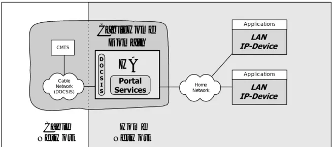
As shown in figure 1, this clause introduces the logical concepts of the Cable2Home domain, logical elements and the Home Access (HA) device class.
Home
Network
Cable
Network
CableHome
Domain
CMTSHA
Portal Services Cable Network (DOCSIS) Home Network Applications LAN IP-Device Applications LAN IP-Device D O C S I SFigure 1: Cable2Home 1.0 Key logical concepts
5.1.1 Cable2Home
domains
The Cable2Home domain represents the set of network elements that are compliant with the Cable2Home specification and is diagrammatically represented as a shaded region in figure 1. This region serves as a visual tool to clearly identify those elements within the home network that are Cable2Home compliant. Elements that reside within the Cable2Home domain (i.e. compliant elements) are directly manageable by cable operators.
5.1.2 Logical
elements
The Cable2Home architectural framework introduces the concept of logical elements. Cable2Home logical elements are logically bounded functional entities that can generate and respond to Cable2Home compliant messages. Cable2Home logical elements operate at the network protocol layer and above, thus remaining independent of any particular physical network technology. They also include the ability to gather and communicate information as needed to manage and deliver services over Cable2Home networks. Cable2Home 1.0 defines a single logical entity known as the Portal Services (PS) element.
5.1.2.1
Portal Services (PS)
A portal is a logical element that provides in-premise and aggregated security, management, provisioning and
addressing services. Within the Cable2Home class of portal services, three portal service sets of functions are defined. They are the management set of functions within the portal services, the Quality of Service (QoS) set of functions within the portal services and the security set of functions within the portal services. The PS logical element forms the foundation of the Cable2Home 1.0 logical reference architecture.
5.1.3 Device
classes
The Cable2Home architecture framework also uses the concept of device classes to lend tangible context to the Cable2Home logical elements and combinations of these logical elements. The Cable2Home concept of device class places no restrictions on physical devices or combinations of logical elements within physical devices. Device classes provide an informative way of depicting collections of logical elements but are not considered definitive or restrictive. Cable2Home 1.0 introduces the concept of the HA device class.
In Cable2Home 1.0, the HA device class represents the physical location of the PS logical element and it enables the network elements within the Cable2Home domain to interact with LAN IP Devices. The HA device has a single DOCSIS RF-compliant interface, a single PS logical element and may have zero or more LAN IP interfaces.
The Cable2Home 1.0 specification [70] also refers to LAN IP Devices. A LAN IP Device is representative of a typical IP device expected to reside on home networks and is assumed to contain a TCP/IP stack as well as a DHCP client.
5.1.3.1
Embedded PS and standalone PS
The two primary components of the HA, the DOCSIS Cable Modem (CM) and the Portal Services (PS) element, may physically interface to one another in a variety of ways. It is the nature of this physical interface between the CM and PS that distinguishes the Embedded PS from the Standalone PS.
The DOCSIS Cable Modem to CPE Interface (CMCI) specification calls out a number of CPE interfaces for a Standalone CM. Examples include the use of Ethernet over any of the following physical interfaces:
• 10Base-T;
• USB; or
• a PCI bus.
A Standalone PS MUST connect to the CM using a CPE interface as defined for a Standalone CM in the DOCSIS CMCI specification. A PS connecting to a CM via any other interface will be considered an Embedded PS. Given this definition, it is possible that a PS might reside within the same physical enclosure as a CM, yet still be considered a Standalone PS.
The CM and the PS are considered to be separate elements in both the Standalone and Embedded cases and they respond to unique management addresses. In the Embedded case, the CM and PS may share hardware and software components, but from the management prospective they are separate entities.
Figure 2 illustrates both the Standalone and Embedded PS. In both of these cases the combination of a CM and a PS is considered to embody the concept of the HA device.
HA Device with
Embedded PS
Physical interface other
than DOCSIS CMCI
Standalone Cable Modem
CPE interface
PS
CM
HA Device withStandalone PS
CM
PS
Standalone Cable
Modem CPE physical
interface as defined
by DOCSIS CMCI spec
Figure 2: Standalone and embedded PS
5.1.4 Address
Realms
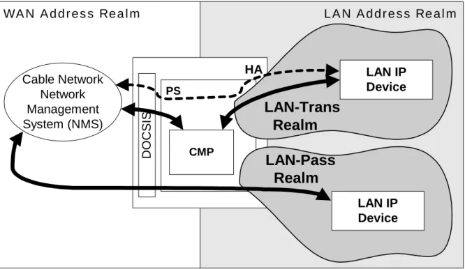
An Address Realm is defined as "a network domain in which the network addresses are uniquely assigned to entities such that datagrams can be routed to them" RFC 2663 [29]. Within the Cable2Home 1.0 specification, address realms are categorized as WAN address realms and LAN address realms (see figure 3).
LAN Address Realm
WAN Address Realm
CableHome
Domain
HA
DHCP Client LAN IP-Device LAN Pass-through Address Realm (LAN-Pass) Service Provider MSO Network (Headend) WAN Management Address Realm (WAN-Man) WAN Data Address Realm (WAN-Data) LAN Translated Address Realm (LAN-Trans) DHCP Client LAN IP-Device PSFigure 3: Cable2Home address realms
WAN addresses reside in one of two realms: the WAN Management Address Realm (WAN-Man) or the WAN Data Address Realm (WAN-Data). LAN addresses also reside in one of two realms:
• LAN Passthrough Address Realm (LAN-Pass); or
• LAN Translated Address Realm (LAN-Trans). The properties of these addressing realms are as follows:
• the WAN Data Address Realm (WAN-Data) is intended to carry subscriber application traffic on the cable network and beyond, such as traffic between LAN IP Devices and Internet hosts. Typically, addresses in this realm will reside in public IP address space;
• the LAN Translated Address Realm (LAN-Trans) is intended to carry subscriber application and management traffic on the home network between LAN IP Devices and the PS element. Typically, addresses in this realm will reside in private IP address space and can typically be reused across subscribers;
• the LAN Passthrough Address Realm (LAN-Pass) is intended to carry subscriber application traffic, such as traffic between LAN IP Devices and Internet hosts, on the home network, the cable network and beyond. Typically, addresses in this realm will reside in public IP address space.
On the LAN side, the addresses in the LAN Passthrough Address Realm (LAN-Pass) are directly extracted from the addresses in WAN Data Address Realm. These are used by LAN IP Devices and applications such as IPCablecom services that are intolerant of address translation and require a globally routable IP address. Additionally on the LAN side, LAN IP Devices may use translated addresses from the LAN Translated Address Realm (LAN-Trans).
5.2
Cable2Home functional reference model
Cable2Home Functions are services (layer-3 and above) defined for Cable2Home 1.0. Cable2Home Functions are located within the PS, LAN IP Devices and the Headend. There are Cable2Home Functions for each of the major Cable2Home specification areas: Provisioning and Management, Security and Quality of Service. The Cable2Home Functions for Provisioning and Management, Security and QoS are briefly introduced in clauses 5.2.1 to 5.2.3.
5.2.1 Cable2Home
management
functions
To support the Cable2Home requirements during the provisioning and management of IP LAN-Devices within the home, three Management Functions classes are defined within Cable2Home:
• management server functions;
• management client functions;
• management portal functions.
Several of the Management Server Functions reside within the MSO Headend (HE). Management Client Functions are typically found within LAN IP Devices. Management Portal Functions are located within the PS logical element and may include server-like, client-like and relay-like functionality to aggregate and translate messages between the MSO Headend and LAN IP Devices. Examples of Management Server, Client and Portal functions are introduced in tables 1, 2 and 3 and are illustrated in figure 4.
Table 1: Management Server Function Description
Management Server Functions Description
Headend DHCP Server The DHCP server is a Headend component
that provides address information for the WAN-Man and WAN-Data address realms to the PS.
Headend Management Messaging server The Cable2Home management messaging,
download, event notification servers including protocols such as SNMP, SYSLOG and TFTP.
Table 2: Management and provisioning portal function description
Management Portal Functions Description
Cable2Home Address Portal (CAP) Within the PS, the CAP interconnects the WAN and LAN address realms for data traffic (see CAT/Passthrough).
Cable2Home Address Translation (CAT) A sub-function of the CAP, a CAT translates addresses on the WAN-Data side of the CAP to addresses within a single logical subnet on the LAN-Trans side.
Passthrough A sub-function of the CAP, the Passthrough
function bridges packets on the WAN-Data side of the CAP to the LAN-Pass side unchanged.
Cable2Home Management Portal (CMP) The function that provides an interfaces between the MSO and the PS -database.
Cable2Home DHCP Portal (CDP) Address information functions (e.g. those
transmitted via DHCP) including a server for the LAN realm and a client for the WAN realms.
Cable2Home Naming Portal (CNP) The CNP provides a simple DNS service for
LAN IP Devices requiring naming services. Cable2Home Testing Portal (CTP) The CTP provides a remote means to initiate
pings and loopbacks within the LAN.
Table 3: Management client function description
Management Client Functions Description
LAN IP Device DHCP Client The Cable2Home DHCP client function is a
in-home component used during the LAN IP Device provisioning process to dynamically request IP addresses and other logical element configuration information. LAN IP Device Loopback responder Within LAN IP Device, the loopback
responder loops data sourced from the CTP loopback function back to the CTP loopback function.
Home
Network
Cable
Network
CableHome
Domain
HA
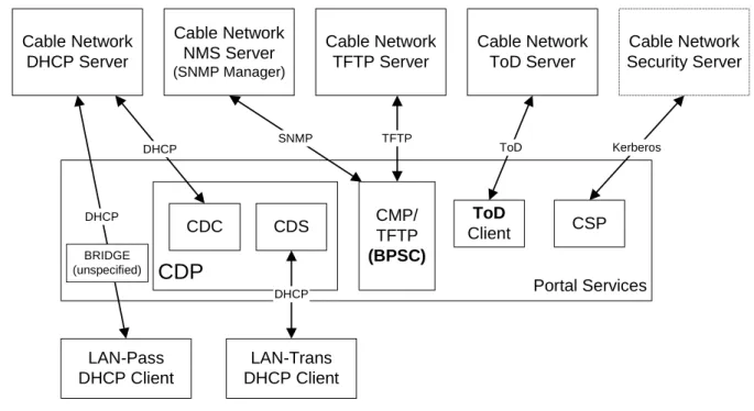
PS CMP CTP CDP CNP CAP LAN IP-Device DNS DHCP Cable Headend SYSLOG NMS TFTP DHCP Home Network LAN IP-Device DNS DHCP Server Function Portal Function Client Function5.2.2
Cable2Home security functions
To support the Cable2Home security requirements, two classes of Security Functions are defined within Cable2Home:
• Security Server Functions (Kerberos, Key Distribution Center);
• Security Portal Functions.
Security Server Functions reside within the MSO Headend (HE) and the Security Portal Functions consist of client-like functions residing within the PS. Examples of Security Server and Security Portal functions are introduced in tables 4 and 5 and are illustrated in figure 5.
Table 4: Security portal function description
Security portal functions Description
Cable2Home Security Portal (CSP) The CSP communicates with Headend
security servers and includes functions that provide client side participation in the authentication, key exchange and certificate management processes defined by
Cable2Home 1.0. Other security functions include management message security, participation in secure download processes and remote firewall management.
Firewall (FW) The Firewall provides functionality that
protects the home network from malicious attack.
Table 5: Security server function description
Security server functions Description
Headend KDC Servers The Headend KDC servers provide security
services to the CSP and include functions that participate in the authentication and key exchange processes defined by
Cable2Home 1.0 [70].
Home
Network
Cable
Network
CableHome
Domain
HA
PS Home Network Server Function Portal Function LAN IP-Device LAN IP-Device Cable Headend KDC CSP FW5.2.3
Cable2Home QoS functions
The Cable2Home QoS architecture is composed of a single PS based functional entity known as the Cable2Home QoS Portal (CQP). The CQP provides transparent bridging for QoS messaging between IPCablecom applications and the IPCablecom QoS infrastructure on the cable network.
5.3
Cable2Home messaging interface model
The communication between the functions in Cable2Home network elements and LAN IP Devices occurs on
Cable2Home defined messaging interfaces. The types of messaging interfaces are differentiated by the elements that are involved in the communication. The Cable2Home Messaging interfaces are illustrated in figure 6.
Home
Network
Cable
Network
LAN IP-DeviceHA
PS HE-LAN IP Device Messaging Interface PS-LAN IP Device Messaging Interface HE-PS Messaging Interface LAN IP-Device Cable Headend (HE)Figure 6: Cable2Home reference interfaces
The Cable2Home Messaging interfaces are summarized in table 6.
Table 6: Valid interface paths for each functionality
Interface
Functionality Protocol HE-PS HE-LAN IP Dev PS-LAN IP Dev
Name service DNS Unspecified Unspecified Cable2Home 1.0
Software Download TFTP Cable2Home 1.0 Unspecified Unspecified
Address Acquisition DHCP Cable2Home 1.0 Unspecified Cable2Home 1.0
Management (single)
(Bulk) SNMP TFTP Cable2Home 1.0 Cable2Home 1.0
Unspecified Unspecified Event Notification SNMP SYSLOG Cable2Home 1.0 Cable2Home 1.0 Unspecified Unspecified
QoS IPCablecom QoS
Protocols
Unspecified IPCablecom Unspecified
Security (key distribution) Kerberos Cable2Home 1.0 Unspecified Unspecified
Security (authentication) Kerberos Cable2Home 1.0 Unspecified Unspecified
Ping ICMP Cable2Home 1.0 Unspecified Cable2Home 1.0
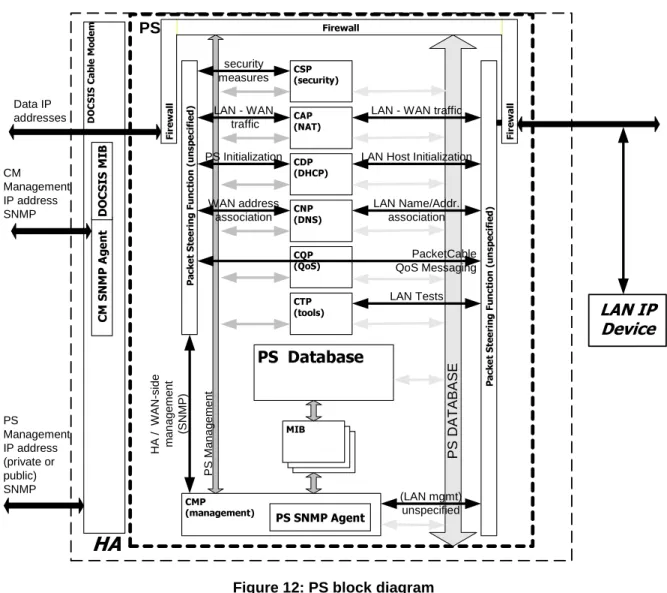
5.4
Cable2Home information reference model
The operation of the Cable2Home management model is based upon a store of information maintained in the PS by the various PS functions (CAP, CDP, CMP, etc.). These functions must have a means of interacting via information exchange and the PS Database is a conceptual entity that represents a store for this information. The PS-Database is not an actual specified database per se, but rather a tool to aid in the understanding of the information that is exchanged between the various Cable2Home elements.
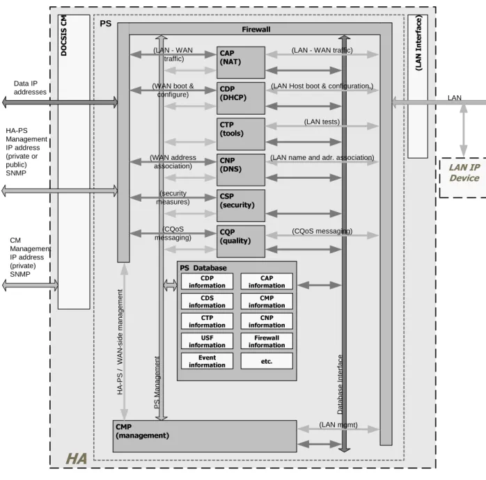
Figure 7 shows the relationship between the database and the PS functions, table 7 describes the typical information associated with each of these functions. Figure 8 shows a detailed example implementation indicating the set of information, the functions that derive the information and the relationships between the functions and the information.
CDP
CMP
CSP
CAP
SNMP / TFTP / SYSLOG UnspecifiedWAN
Management
Interface
LAN
Management
Interface(s)
PS
Database
PS
FW
CTP
CNP
CQP
Figure 7: PS function and database relationship
The PS Database stores a myriad of data relationships. The CMP provides the WAN management interface (SNMP) to the PS database. The Cable2Home functions within the PS enter and revise data relationships in the PS Database. Additionally, the Cable2Home Functions within the PS may retrieve information from the PS Database that is maintained by other Cable2Home Functions within the PS.
Table 7: Typical PS database information examples
Name Usage (in general)
CDP Information Information associated with addresses
acquired and allocated via DHCP.
CAP information Information associated with Cable2Home
address translation mappings.
CMP information Information associated with the state of the
management functions.
CTP information Information associated with results of LAN
test performed by the CMP.
CNP information Information associated with LAN IP Device
name resolution.
USFS information Information associated with the Upstream
Selective Forwarding Switch function.
CSP information Information associated with authentication,
key exchange, etc.
Firewall information Information associated with the behaviour of
the Firewall (rule set) and firewall logging.
Event information Information associated with the local log for
D O C SI S C M
CAP
(NAT)
CMP
(management)
PSCDP
(DHCP)
PS Database
CM Management IP address (private) SNMP Data IP addresses Da ta ba s e Inte rfa c e P S M ana gem entHA
(LAN mgmt) HA-PS Management IP address (private or public) SNMP CNP (DNS) CDPinformation informationCAP CMP information
CNP information USF
information informationFirewall
CSP (security) CTP (tools) (L A N I n te rf ac e) H A -P S / WA N -s ide m ana gem ent CTP information Event information CQP (quality) LAN LAN IP Device CDS information etc. Firewall (LAN tests) (LAN Host boot & configuration.)
(LAN name and adr. association) (LAN - WAN traffic)
(CQoS messaging) (LAN - WAN
traffic)
(WAN boot & configure) (WAN address association) (security measures) (CQoS messaging)
Figure 8: PS database detailed example implementation
The PS is managed from the WAN via the CMP and to a large degree this involves access to the information in the PS Database. Management is used for initialization and provisioning of the WAN side network elements and diagnostics or status of the LAN. The diagnostics may rely on the CTP to get better visibility into the current state of the LAN. Connectivity and rudimentary network performance can be measured.
The CNP is the LAN Domain Name System (DNS) manager. All LAN-Trans LAN IP Devices are configured by the CDP to use the CNP as the primary Name Server. The CNP resolves textual host names of LAN IP Devices, returning their corresponding IP addresses and in addition, refers LAN IP Devices to external DNS servers for requests that cannot be answered from local information.
The CDP contains the address functions to support the DHCP server in the LAN-Trans realm and a DHCP client in the WAN realms.
The CAP creates address translation mappings between the WAN-Data and LAN-Trans address realms. The CAP is also responsible for Upstream Selective Forwarding Switch decisions to preserve HFC upstream channel (WAN) bandwidth from the local LAN only traffic. Finally, the CAP contains the Passthrough function, which bridges traffic between the LAN and WAN address realms.
The CQP is part of a system that enables IPCablecom Quality of Service (QoS) through the PS. The CQP, acting as a transparent bridge, forwards IPCablecom compliant QoS messaging between IPCablecom applications and the IPCablecom QoS infrastructure.
5.5
Cable2Home operational models
The functionality of the Portal Services element is compatible with a variety of cable network infrastructures, which are accommodated by a number of different PS operational modes. These various operating modes enable the PS to function properly within a DOCSIS 1.0 infrastructure, a DOCSIS 1.1 infrastructure and within an Extended
Cable2Home infrastructure. The Extended Cable2Home infrastructure builds upon DOCSIS 1.0 and 1.1 infrastructures to enable additional services and incorporates a number of capabilities that are similar to those within a IPCablecom provisioning system.
For the purpose of configuration, the PS may operate within one of two provisioning modes:
• the DHCP provisioning mode;
• the SNMP provisioning mode.
When the PS is operating within the DHCP Provisioning Mode, it can operate in one of two Network Management sub-modes:
• NmAccess mode;
• coexistence mode.
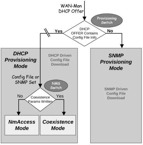
Figure 9 illustrates the various PS operational modes along with the associated triggers for each. See clause 6.3.6.1.1.
SNMP
Provisioning
Mode
SNMP Driven Config File DownloadDHCP
Provisioning
Mode
Config File or SNMP Set Coexistence Params Written YesCoexistence
Mode
NmAccess
Mode
No NMS Switch DHCP Driven Config File Download WAN-Man DHCP OfferYes OFFER ContainsDHCP
Config File Info
No Provisioning
Switch
If PS Configuration File information (server location and file name) is provided to the PS in the DHCP OFFER issued by the cable network DHCP server, the PS will operate in DHCP Provisioning Mode. When in DHCP Provisioning Mode, the PS may operate in one of two Network Management Modes (NmAccess and Coexistence). Within DHCP Provisioning Mode, the PS will operate in NmAccess Network Management Mode by default, but can be configured by the NMS to operate in Coexistence Mode.
If PS Configuration File information is not provided to the PS in the DHCP OFFER issued by the cable network DHCP server, the PS will operate in SNMP Provisioning Mode. When operating in the SNMP Provisioning Mode, information and triggers for PS Configuration File download are provided by the NMS via SNMP messaging. As opposed to the DHCP Provisioning Mode, the network management behaviour does not vary within this mode.
Table 8 describes the infrastructures within which each PS mode is intended to operate.
Table 8: PS infrastructures
Mode Capability Directly Effected Intended Infrastructure
SNMP Provisioning Mode Configuration file download Extended Cable2Home Infrastructure DHCP Provisioning Mode Configuration file download DOCSIS 1.0 and 1.1 Infrastructures DHCP Provisioning Mode:
NmAccess Mode
SNMP version used between NMS and PS
DOCSIS 1.0 Infrastructure (SNMP v1/v2)
DHCP Provisioning Mode: Coexistence Mode
SNMP version used between NMS and PS
DOCSIS 1.1 and Extended Cable2Home Infrastructures (SNMP v3)
5.6
Cable2Home physical interfaces
There are many types of physical interfaces that may be implemented on a device containing PS functionality. Several are described in the following list:
• WAN Networking Interfaces, which include the Radio Frequency Interface (RFI) as described by DOCSIS for the Embedded PS case and other WAN Networking Interfaces, intended for WAN connection, in the
Standalone PS case.
• LAN Networking Interfaces for connection to LAN IP Devices.
• Hardware test interfaces, such as JTAG and other proprietary approaches, which are part of the silicon and do not always have software controls to turn the interfaces off. These interfaces are hardware state machines that sit passively until their input lines are clocked with data. Though these interfaces can be used to read and write data, they require an intimate knowledge of the chips and the board layout and are therefore difficult to "attack". Hardware test interfaces MAY be present on a device implementing PS functionality. Hardware test interfaces MUST NOT be either labelled or documented for customer use.
• Management access interfaces, also called console ports, which are communications paths (usually RS-232, but could be Ethernet, etc.) and debugging software that interact with a user. The software prompts the user for input and accepts commands to read and write data to the PS. If the software for this interface is disabled, the physical communications path is disabled. A PS MUST NOT allow access to PS functions via a Management Access Interface. (Cable2Home PS functions are defined by the Cable2Home specification.) Access to PS functions MUST only be allowed via interfaces specifically prescribed by the Cable2Home specifications, e.g. operator-controlled access via SNMP.
• Read-only diagnostic interfaces can be implemented in many ways and are used to provide useful debug, trouble-shooting and PS status information to users. A PS MAY have read-only diagnostic interfaces.
• Some products might choose to implement higher layer functions (such as customer premise data network functions) that could require configuration by a user. A PS MAY provide the ability to configure
non-Cable2Home functions. Management interface (read/write) access to PS functions MUST NOT be allowed through the mechanism used for configuring non-Cable2Home functions.
6 Management
tools
6.1 Introduction/overview
The Cable2Home Management Tools provide the cable operator with functionality to monitor and configure the Portal Services (PS) element, as well as to perform remote diagnostics on LAN IP Devices. This clause describes and specifies requirements for these capabilities.
6.1.1 Goals
The goals for the Cable2Home Management Tools include:
• provide cable operators with visibility to LAN IP Devices;
• provide cable operators with a minimum set of remote diagnostic tools that will allow the cable operator to verify connectivity between the Portal Services element and any LAN IP Device in the LAN-Trans address realm;
• provide cable operators with access, via the MIBs, to internal data in the PS element and enable the cable operator to monitor Cable2Home-specified parameters and to configure or re-configure Cable2Home-specified capabilities as necessary;
• provide a means for reporting exceptions and other events in the form of SNMP traps, messages to a local log, or messages to a System Log (SYSLOG) in the cable network.
6.1.2 Assumptions
The assumptions for the Cable2Home network management environment include:
• Cable2Home-compliant devices implement the Internet Protocol (IPv4) suite of protocols;
• SNMP is used for the exchange of management messages between the cable network NMS and the
Cable2Home-compliant PS in the HA device. SNMP provides visibility for the NMS to interfaces on the PS, via access to internal PS data, through required MIBs;
• any of SNMPv1/v2c/v3 can be used as a management protocol between the NMS and the Cable2Home Portal Services element;
• LAN IP Devices implement a DHCP client;
• information acquired through the exchange of DHCP DISCOVER, DHCP REQUEST and DHCP OFFER messages exchanged between the PS and LAN IP Devices and information available from the PS database (see clause 5.4) through the Interfaces Group MIB are sufficient to provide the cable operator with desired
knowledge about LAN IP Devices;
• the PS element and LAN IP Devices support ICMP;
• the PING utility supplies functionality sufficient to provide the cable operator with the desired information about connectivity between the PS element and LAN IP Devices.
6.2 Management
architecture
6.2.1
System design guidelines
The Cable2Home 1.0 Management Tools system design guidelines are listed in table 9. This list provided guidance for the development of the Cable2Home management tools specifications.
Table 9: Management tools system design guidelines
Reference Management Tools System Design Guidelines
Mgmt 1 The PS will implement SNMPv1/v2c/v3 to provide access to internal Portal Services data.
Mgmt 2 The PS will be capable of issuing a an ICMP Ping command to any specified LAN IP Device in the LAN-Trans realm at the direction of the cable network NMS and store results in the PS Database. Remote Ping test results are accessible through CTP MIB objects
cabhCtpPingStatus, cabhCtpPingNumSent and cabhCtpPingNumRecv. Mgmt 3 The PS will be capable of executing a Connection Speed Test with a
specified LAN IP Device in the LAN-Trans realm at the direction of the cable network NMS and store results in the PS Database.
Mgmt 4 The PS element will be capable of reporting events.
6.2.2
Management tools system description
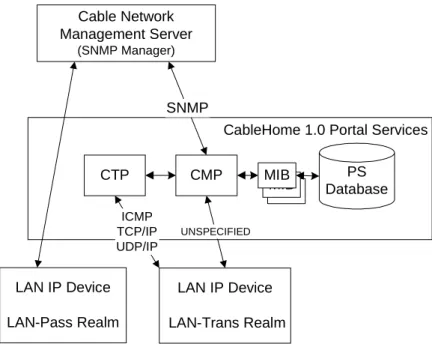
As shown in figure 10, Cable2Home Management Tools architecture consist of the following components: 1) the Cable2Home Management Portal (CMP),
2) the Cable2Home Test Portal (CTP),
3) an Event Reporting mechanism within the CMP and
4) an SNMP Network Management System (NMS) that is part of the cable network.
The cable network NMS monitors and configures the PS by accessing the PS Database through MIBs specified in clause 6.3.7. The NMS may also directly communicate with LAN IP Devices in the Cable2Home LAN-Pass realm.
CableHome 1.0 Portal Services
CTP CMP LAN IP Device LAN-Trans Realm LAN IP Device LAN-Pass Realm Cable Network Management Server (SNMP Manager) PS Database MIB MIB MIB ICMP TCP/IP UDP/IP UNSPECIFIED SNMP
Figure 10: Cable2Home management architecture
The CMP and CTP functional elements reside within the PS. The PS logical element may be embedded or stand alone, relative to the cable modem functionality, as described in clause 5.