V.90 Modem
This handbook is protected by copyright. It must not be copied, reproduced, translated or transmitted in electronic media, in whole or in part.
Accuracy of the information is not guaranteed.
Any mention in this handbook of products of other manufacturers is for in-formation purposes only and represents no misuse of trademarks.
Safety instructions for Data-Fax-Modem
This equipment has been designed and tested in accordance with the requirements of Standard IEC 950 „Safety of Information Technology Equipment, Including Electrical Business Equipment“
Extracts from these requirements according Standard IEC 950:
• The fax-modem may only be powered by the delivered direct plug-in power supply AA-09/ABN, 230 VAC, 50 Hz, according to IEC 950, class II equipment.
• The connection to the mains supply will be done by the delivered plug-in power supply. The mains supply socket must be accessible easily.
• A defective power supply must only be replaced by a powersupply of the same type.
• The fax-modem has been evaluated for use in office environment (pollution degree 2) and may only be used in this environment. For use in rooms with a higher pollution degree more stringent requirements are applicable.
• The fax-modem may not be opened.
• The ventilation opening may not be covered.
• The fax-modem was evaluated for use in maximum ambient temperature of 35 °C.
• The fax-modem may only be used in countries where the modem is certified.
• Neither the data transmission cable nor the telephone cable should be connected or disconnected during a thunderstorm.
Table of Contents
Chapter 1
INTRODUCTION
. . . 1-1
What is a Modem? . . . .1-1 About this Modem . . . .1-1 The 56K Technologie. . . .1-2 General Description . . . .1-2 Auto-Answering. . . .1-3 Attention . . . .1-3 Installation Instructions . . . .1-3 Windows 95/98 . . . .1-3 Installation with Windows NT4.0 . . . .1-4 Factory Settings . . . .1-4 LED Indicators. . . .1-5 Schematic Representation . . . .1-5 Manufacturer Declaration . . . .1-5 Electromagnetic Confirmity. . . .1-6 Safety Requirements . . . .1-6
Chapter 2
AT COMMANDS: DATA MODEM . . . . 2-1
Guidelines for Using AT Commands . . . .2-1 AT - Attention Code . . . .2-3 The ESC Sequence. . . .2-3 A - Answer Mode. . . .2-4 A/ - Repeat Last Command Line . . . .2-4 B - BELL/CCITT Standard . . . .2-4 D - Automatic Dialling and Dialling Parameters . . . .2-5 E – Echo Function . . . .2-6 H – Switch Hook Check (Replace Handset) – Go "On Hook" . . . .2-6 I – Firmware Information. . . .2-6 L – Volume Level . . . .2-6
II
M – Switching the Loudspeaker On and Off . . . 2-6 N – Recognizing Type of Modulation . . . 2-7 O – Return to On-Line Operation. . . 2-7 Q – Modem Messages On / Off . . . 2-7 S – Reading and Modifying Registers . . . 2-7 V – Verbal or Numeric Modem Messages . . . 2-7 W – Controlling Connect Messages . . . 2-8 X – Result Code Type/Call Progress . . . 2-9 Y – Long Space Disconnect . . . 2-9 Z – Reset Modem/Record Stored Profile . . . 2-9 &C – DCD (Data Carrier Detect) Option. . . 2-9 &D – DTR (Data Terminal Ready) Option . . . 2-10 &F – Loading the Factory Settings . . . 2-10 &G – Guard Tone . . . 2-11 &K – Select Serial Port Flow Control . . . 2-11 &S – DSR (Data Set Ready) . . . 2-11 &T – Data Mode Self-Test Command . . . 2-11 &V – View Active Configuration and Stored Profiles . . . 2-12 &W – Storing a set Profile . . . 2-12 &Y – Selecting a Start Configuration. . . 2-12 &Z – Telephone Number Storage. . . 2-13 +MS – Select Modulation. . . 2-13 \A – MNP Block Size . . . 2-16 \B – Sending a Break Signal. . . 2-16 \C – Set Auto-Reliable Buffer . . . 2-16 \G – Set Modem Port Flow Check . . . 2-16 \J – bps Rate Adjust Control . . . 2-17 \K – Set Break Control . . . 2-17 \N – Set Oparating Mode . . . 2-18 \Q – Set Serial Port Flow Control. . . 2-18 \T – Set Inactivity Timer. . . 2-19 \X – Set XON/XOFF-Pass Through . . . 2-19 -J – Set V.42 Detect Phase . . . 2-19
%C – MNP5 Data Compression Control . . . .2-19 %E – Auto-Retrain Control . . . .2-20 %G – Rate Renegotiation. . . .2-20 "H – V.42bis Compression Control . . . .2-20 "O – V.42bis String Lengh . . . .2-20
Chapter 3
MODEM MESSAGES . . . 3-1
Chapter 4
S-REGISTERS . . . 4-1
S0 – Number of Ring Characters before Modem engages . . . .4-2 S1 – Ring Character Counter . . . .4-2 S2 – Esc Sequence Character. . . .4-2 S3 – Carriage Return Character . . . .4-2 S4 – Line Feed Character. . . .4-2 S5 – Backspace Character . . . .4-2 S6 – Waiting Time for Dial Tone . . . .4-2 S7 – Waiting for Carrier Signal . . . .4-3 S8 – Pause Time after Comma. . . .4-3 S9 – Answer Time after Carrier Recognition. . . .4-3 S10 – Delay between Carrier Loss and Hanging Up . . . .4-3 S12 – Guard Time for Esc Sequence . . . .4-4 S14 – General Options . . . .4-4 S16 – Modem Test Options . . . .4-5 S18 – Test Timer . . . .4-5 S21 – V.24/General Options. . . .4-5 S22 – Loudspeaker/Authorised Modem Messages . . . .4-6 S23 – General Options . . . .4-6 S25 – DTR Delay Time . . . .4-7 S27 – General Options . . . .4-7 S30 – Inactivity Timer . . . .4-7 S33 – Sleep Modem Timer . . . .4-8 S37 – Maximum Line Speed Attempted . . . .4-8
IV
TECHNICAL INFORMATION. . . A-1
GLOSSARY . . . A-1 CCITT RECOMMENDATIONS . . . A-2 Technical Specifications . . . A-3
Chapter 1
INTRODUCTION
The Data Modem you have purchased represents the latest state of the art in data communication; its comprehensive facilities provide all you will need for profes-sional data transfer purposes.
Due to the limitation this equipment allows you to receive data with up to 54kbps from your Internet Service Provider (ISP). The maximum transmission speed ist 33.6kbps. Fax transmission and reception is working up to 14.4kbps.
This handbook, together with the descriptive information provided with your communications and fax software, gives all the information you need to install and operate the equipment.
What is a Modem?
The word “Modem” is derived from the terms “MOD-ulator” and “DE-modula-tor”. Putting it more simply, it is a device which modulates digital information into an analogue carrier signal (tones) and demodulates the carrier signals which it re-ceives, changing them back into digital data. This permits the transmission of data along wires, between data terminal equipment (computers, terminals, etc…). About this Modem
This modem operates as a full duplex, voice-band modem, where signal transmis-sions are made in both directions simultaneously and the analogue signals which are transmitted are in the voice-band of the telephone network.
Data transmission between modem and terminal unit is in serial form - in other words, the individual data bits are sent, one after another, along a single transmis-sion or receiving line. At this stage, a word of explanation regarding synchronous and asynchronous data transmission. In the synchronous mode, additional syn-chronisation signals are required, to synchronize the transmission and reception si-gnals. In the asynchronous mode synchronisation is by means of “start-bits” and “stop-bits” which mark the beginning and end of each data word. The modem can dial by itself and also react automatically to incoming calls. The information it needs in order to dial a telephone number, together with the various configuration commands, are provided by the respective data terminal equipment via the same serial interface which is used to send the data. In this mode, the system operates with the so-called “AT” command set.
1-2 INTRODUCTION
The 56K Technologie
The V.90 modem represents the latest V.90 technology. This allows receive data rates of up to 57.333 kbps over PSTN (public switched telephon network) only in connection withe equipment-compatible ISPs (Internet Service Provider): howe-ver, due to the limited power levels of the PSTN the receive speed is limeted to 54 kbps.
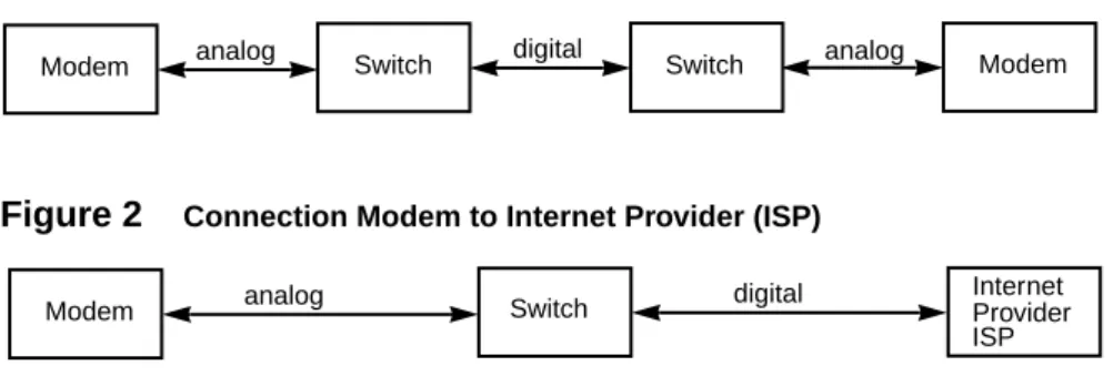
Figure 1 Connection Modem to Modem
Figure 2 Connection Modem to Internet Provider (ISP)
General Description
• Up to 54 kbps receive data rates in V.90 mode • Fax send and receive up to 14400 bps
(Fax groupe 3, according to V.29, V.27ter, V.17) • Max. transmission speed up to 33.6 kbps
• Asynchronous communication between modem and computer • V.42bis data compression
• V.42 and MNP2-4 error correction
• Effective data rate up to115.200 bps (V.34 and V.42bis) • Number storage for 4 telephone numbers
• Automatic baudrate-adaption up to 115.200 bps • AT-command set
• Voice capabilities • Internal speaker
• Jacks for external speaker and microphone • Flash rom
• Win 9x PnP • On/Off switch
Modem analog Switch digital Switch analog Modem
Modem analog Switch digital InternetProvider
Auto-Answering
With the delivered Software you can use your Modem like an answering machine. Voicemail can be recorded over the soundcard or the extern microphone. To re-play recorded voice or messages you can use a soundcard or an external Loudspea-ker.
Attention:
The modem will be powered by the delivered power supply. Plug in this power supply to a power socket with 230-240 VAC, 50 Hz. Make sure you can reach the power socket and the power supply easily.
Installation Instructions
1. Use the interface cable supplied to connect the modem to a free COM inter-face on the computer
2. Use the telephone cable supplied to connect the modem to a Telephone jack 3. This device must only be connected to computers or other device that are in accordance to EN 60950 regulation and fulfill the respective EMC and safety standards.
4. When the “POWER” LED is lit, the modem is ready for operation and will provide data communication, using the factory settings which have been in-stalled
Windows 95/98
Windows 9x will recognize the modem after a reboot of your PC. Put in the CD with the driver when Windows 9x asks for it and follow the instructions on the screen. Please read the instructions for the installation of new hardware in your Windows-Manual.
If you don’t find your modem in the actual modemlist you can choose a standard modemdriver.
=>Now you can configure and use the modem with the communications-, fax- and Voiceprograms.
1-4 INTRODUCTION
Installation with Windows NT4.0
Open the option modem withe Start – Settings – Control Panel– Modem. The modem installation window will be opend. In this window press the button:
Choose modem (no automatic recognition) and the button Next. Press the button
Diskette. Put in the CD which has been delivered with the modem and select the CD drive. A list will be shown with all the modem-drivers. Choose your modem and press the button Next. In this window choose the com port to which the modem shall be connected, for example com2, and press the button Next. The con-figuration of your modem will be started. Press the button Finish to finish the in-stallation. Please read the instructions for the installation of new hardware in your Windows-Manual.
If you don’t find your modem in the actual modemlist you can choose a standard modemdriver, too.
Factory settings
To make it easier for you to use your modem, two basic settings have been made at the factory, which are suitable for most of the connections. These settings can be activated with the “&F” command. In the fax mode or voice mode, the relevant software will carry out control of modem settings for you.
• For Data Transmissions select AT&F0. In this condition, the modem will attempt to create an error-corrected connection with data compression, de-pending on the capability of the remote side.
What the LED Indicators mean:
• MR Modem is ready for operation • OH Modem is off hook
• CD Modem has recognized the carrier tone from the remote modem
• CS Modem is ready to transmit (clear to send) • RS Transmission request is present (request to send)
• TR DTR-Computer is ready for operation (data terminal ready) • RD RxD receive data
• SD TxD transmit data
Schematic Presentation
Manufacturer Declaration
This Produkt fullfills the requirements of the EC council directives (89/336/EEC, 73/23/EEC and 98/13/EC)
On/Off Switch Powersupply COM-Interface
ON
OFF
Power RS-232 MIC SPK LINE
Telephonline External Speaker Microphon
CS RS CD OH RD SD TR MR
V.90
1-6 INTRODUCTION
Electromagnetic Confirmaty
=>All equipment connected to this device must be approved according to the EC council directive 89/336/EEC.
Safety Requirements
=>All equipement connected to this device must fulfill the safety requirements of the EN 60950: 1992+A1+A2+A3+A4.
Chapter 2
AT COMMANDS:
DATA MODEM
Guidelines for Using AT Commands
The modem is programmed with AT commands from the data terminal equipment (computer, PC or terminal) and thus also receives instructions to cover automatic dialling. The communications or fax software will carry out most of these operati-ons for you, so that in general circumstances you do not need to have a detailed understanding of the commands which are described below.
The modem must be in Command mode before it can accept commands. In this condition, all the characters sent from the computer are interpreted as commands and, where appropriate, confirmed by a modem message on the screen. When a connection is set up to a remote modem, the modem will switch to data mode and transfer all the characters it receives to the other party.
The modem can be switched from an existing connection, back into the com-mand mode, by using the Esc Sequence (+++), without breaking off the connec-tion to the remote modem. In this status, any commands which are entered will not be transferred to the remote modem.
The modem is activated by AT commands, the subsequent value of which will modify the form of the command. Modem messages provide information on the form of the commands.
In the Hayes Command Set, commands are entered by the character sequence
AT (at) and can also be entered as a list of commands with or without spaces
bet-ween the individual commands. The “Backspace” key is used for deleting. Com-mands can be entered in upper-case or lower-case. In the command mode, the modem automatically recognizes data frames and data speed.
=>AT commands can be transferred to the modem at the following data speeds: 115 200, 57600, 38400, 19200, 9600, 4800, 2400, and 1200 bps
Examples of Command Syntax: ATX3<CR>
ATQ0<CR> ATDT12345<CR>
Individual commands ending with the <CR> Enter key, can be entered in a diffe-rent manner with the same effect, by inserting as many spaces as you need, to make the command easier to visualise
ATX3QODT12345<CR> or: AT X3 Q0 DT 12345<CR>
2-2 AT COMMANDS: DATA MODEM
Table 1 Modem Commands
Standard Commands
ATA Answer mode: Modem monitors telephone line
A/ Repeat last command line; entered without “AT”
ATB Switching between BELL/CCITT Standards at 300 or 1200 bps
ATD Enter automatic dialling
ATE Controlling of echo modem commands on screen
ATH Break off an existing connection
ATI Information on Modem product code
ATL Loudspeaker volume control
ATM Switch on loudspeaker
ATN Select Data Rate Handshake
ATO Return to Online-mode after entering Esc sequence
ATQ Controlling modem messages
ATS Read and modify modem register(s)
ATT Select Tone dialling
ATV Modem message format (verbal or numeric)
ATW Directing speed messages
ATX Modem function during dialling; modem messages
ATY Long Space Disconnect
ATZ Modem Reset and Load one of the stored modem profiles
+++ Escape Sequence to return temporarily to Command mode
AT&C Controlling M5 (DCD) Signal at the serial interface
AT&D DTR Option
AT&F Load the factory setting
AT&G Switch on a Guard Tone
AT&K Flow Check
AT&R Controlling M2 (CTS) and S2 (RTS) Signal at the serial interface
AT&S Controlling M1 (DSR) Signal at the serial interface
AT&T Modem test functions
AT&V Displaying current configuration
AT&W Storing Modem settings
AT&Y Selecting the configuration which will be active after modem start
AT&Z Storing telephone numbers
AT+MS Select Modulation
Erweiterte MNP- und V.42bis-Befehle
AT\A MNP Block Size
AT\B Transmit Break
AT\G Set Modem Port Flow Control
AT\J bps Rate Adjust Control
AT\K Set Break Control
AT\N Set Operating Mode
AT - Attention Code
The AT (Attention) Code, which introduces each command line, can be entered in upper-case or lower-case characters.
Several commands (separated by spaces if desired) can be positioned one after another, in one line. A command line must end with the ASCII character which is stored in the S3 or S4 Register (or with both together). The standard value for S3 is Carriage Return (<CR>=13 decimal) and Line Feed (<LF>=10 decimal) for S4.
A command line without <CR>,<LF> will remain in the command buffer until <CR>,<LF> is entered, or until the action is broken off with <Cntrl-X>. Once <CR>,<LF> has been received, the modem carries out the commands following the AT and answers with an appropriate modem message.
The maximum length of a command line is 40 characters. If the capacity of the command buffer is exceeded, the modem issues an Error message.
=> The AT code enables the modem to recognize the speed, parity and
character-length of the communication programm
The ESC Sequence
If the modem has established a data connection, you can enter more commands at any time, without breaking off the connection. This is achieved by sending three ASCII characters (S2 Register) from the computer to the modem. The standard setting is the “+” character. In order for this to be interpreted as the ESC sequence, certain time limits must be observed in entering the plus-characters. Before the first and after the last character, a Guard time is required (the standard is 1 second) and the individual characters must not be separated from each other by longer than this time period.
Extended MNP- and V.42bis-Commands
AT\T Set Inactivity Timer
AT\X Set XON/XOFF Pass-Through
AT-J Set V.42 Detect Phase
AT%C MNP 5 Data Compression Control
AT%E Auto Retrain Control
AT%G Rate Renegotiation
AT"H V.42 bis Compression Control
2-4 AT COMMANDS: DATA MODEM
A - Answer Mode
When the A command is entered, the modem switches to the “Off-Hook” condi-tion when ringing appears in the answer mode and takes over control of the tele-phone line connected. In this way, the modem transmits in the upper frequency band (upper channel)
If further commands are entered after the A command before a connection has been made, the modem interrupts the establishment of a connection, switches to command mode and issues a NO CARRIER message.
If no carrier is received from the remote station after the waiting time which is set in the S7 Register, the modem responds with a NO CARRIER message and re-turns to command mode. If the modem does receive the carrier signal, it issues a CONNECT message and switches to Data mode.
=> If the handset is not replaced after the data transmission has been completed,
the connection remains online and you will continue to pay for this !
A/ - Repeat Last Command Line
The A/ command causes the modem to repeat the command line which is stored in the command buffer, e.g. it will dial again, if the line is busy. This command is en-tered without AT and no reply is issued.
=> A command line remains in the repetition buffer until the modem receives a
new command. The data format should not be modified in the meantime.
B - BELL/CCITT Standard
The B command permits change-over between CCITT and Bell standards at 300 or 1200 bps. At 300 bps, this command will select between Bell 103 and CCITT V.21, while at 1200 bps it will select between Bell 212A and CCITT V.22.
ATB0 CCITT V.22, V.21
ATB1 Bell 212A, Bell 103 (factory setting)
=> The B command refers only to connections at 300 or 1200 bps. All other
D - Automatic Dialling and Dialling Parameters
The D command instructs the modem to go on-line and to dial. If this command is entered without parameters, the modem will go on-line in Originate mode. The following characters are authorised in the dialling sequence:
0 - 9 The digits of the telephone number
P, T In the Dial command, these parameters switch to pulse-dialling (P) or to tone-dialling (T) until the other parameter is entered. The standard setting is tone-dialling.
W Dialling tone recognition. When this parameter is entered, the modem will not continue dial until it has recognized the sign that the line is free. This is an advantage in branch exchanges, where it is not always possible to guarantee immediate access to a line. , Dialling pause (2 sec). This comand may not be used in the
ling sequence when the modem is supposed to wait for a new dial-tone. The W-parameter must be used in this case.
A-D,*,# Additional characters when tone-dialling
S=n Dialling number which is stored with &Zn
! Call exchange by Flash
;H Modem as automatic dialling device. Here, the dialling sequence is terminated by a semi-colon, followed by the H command. The modem goes off-line after dialling and you can take over the con-versation using a telephone. The handset must be lifted during the dialling process.
Example of how to set up a Dial Command ATD T0, 02212971
With this, a private automatic branch exchange using tone-dialling dials zero, in order to obtain an exchange line. The modem then waits two seconds to dial the rest of the telephone number.
Example of the Automatic Dialling Function ATD T0, 02212971;H
If you lift the handset during the dialling process, you can take over the connec-tion yourself.
=> Where appropriate, ask the manufacturer of your private automatic branch
ex-change what specific features need to be taken into account in the dialling pro-cedure
=>If the handset is not replaced after the data transmission has been completed, the connection remains made and you will continue to pay for this!
2-6 AT COMMANDS: DATA MODEM
E – Echo Function
The E command determines whether the modem will issue an echo of the com-mand which is entered.
ATE0 Echo disabled
ATE1 Echo enabled (factory setting)
H – Switch Hook Control (Replace Handset) – Go "On Hook" The H command will break off the existing telephone line connection (the modem “hangs up”) and the connection to the remote modem is cut off. After the H com-mand, any other commands in the same line are ignored.
=>This command can only be entered after an existing data link has been quitted by using the Esc sequence.
I – Firmware Information
ATI0 Report product code
ATI1 Verifies ROM checksum
ATI2 Modem chip firmware version #
ATI3 Reports chipset name
ATI4 EPROM Version
ATI6 Country Code L – Volume Level
The loudspeaker enables you to follow acoustically as the connection is esta-blished and data are transmitted.
ATL0,1 Low speaker volume
ATL2 Medium speaker volume (factory setting)
ATL3 High speaker volume
M – Switching the Loudspeaker On and Off
ATM0 Speaker always OFF
ATM1 Speaker on until carrier present (factory setting)
ATM2 speaker always ON
N – Recognizing Type of Modulation
This command commands the automatic recognition of the type of modulation.
ATN0 When originating or answering, connect only at the data rates specified by the modulation.
ATN1 When originating or answering, begin handshaking at the modula-tion data rate. If the remote modem does not support the specified modulation data rate, fall down in data rate or modulation to the highest campatible data rate.(factory settings)
O – Return to On-Line Operation
The O command causes the modem to return to Online mode, which had been left temporarily, using the Esc sequence. With the remote modems still online, you can continue data transmission.
Q – Modem Messages On / Off
ATQ0 Result codes enabled(factory setting)
ATQ1 Result codes disabled
S – Reading and Modifying Registers
This command gives access to the internal modem registers. See chapter 4 for de-tails of the possible values.
ATSn=v This sets Register n to the (decimal) value v
ATSn=v? This sets Register n to the (decimal) value v and sends the new value for checking
ATSn? This reads Register n and gives its value in decimal form
V – Verbal or Numeric Modem Messages
The V command determines the type of message which the modem returns to the computer.
ATV0 Numeric form
2-8 AT COMMANDS: DATA MODEM
W – Controlling Connect Messages
This command controls the format of CONNECT messages.
ATW0,1 CONNECT result code reports DTE speed
ATW2 CONNECT result code reports DCE speed
ATW3 CONNECT result code reports DTE data rate, modulation mode, error correction, data compression, DCE transmitter speed and DCE receiver speed when the mode is configured for verbose V1 (text) response codes. For numeric responses V0, the modem sponds with the W0 numeric response codes. The verbose re-sponse codes use the following format:
CONNECT (DTE data rate)/(modulation)/(error correction)/(data compression)/TX=(DCE transmit data rate)/RX=(DTE receive data rate)
Modulation types include: V21, V22, V22B, V23C, V32, V32B, V32B, V34
Error correction types include: NONE, LAPM, MNP Data compression types include: NONE, V42B, MNP5
For example: CONNECT 115200/V34/LAPM/V42B/TX=28800/RX=28000
ATW4 CONNECT result code reports DTE protocol, data compression, and DTE data rate when the mode is configured for verbose V1 (text response codes). For numeric responses V0, the modem sponds with the WO numeric response codes. The verbose re-sponse codes use the following format:
(DTE protocol) (date compression) (line speed)
Error correction types include: NONE, LAPM, MNP Data compression types include: NONE, V42B, MNP5
X – Result Code Type/Call Progress
This comand determines which modem result codes are enabled. Additionally, this command specifies whether busy and dial tone detection are enabled or disabled..
ATX0 Result codes 0-4 enabled. Busy and dial tone detect disabled.
ATX1 Result codes 0-5, 10 and above enabled. Busy and dial tone detect disabled.
ATX2 Result codes 0-6, 10 and above enabled. Busy detect disabled and dial tone detect enabled.
ATX3 Result codes 0-5, 7, 10 and above enabled. Busy detect enabled and dial tone detect disabled.
ATX4 Result codes 0-7, 10 and above enabled. Busy and dial tone detect enabled (factory setting).
Y – Long Space Disconnect
This command determines whether the modem disconnects after receiving 1.6 se-conds of silence and whether the modem sends a period of silence to the remote modem before disconnecting.
ATY0 Disables long space disconnect (factory setting)
ATY1 Enables long space disconnect. The modem disconnects after re-ceiving 1.6 seconds of silence from the remote modem. Additio-nally, after receiving an ATH0 command, the modem sends at least 4 seconds of silence before hanging up.
Z – Reset Modem/Recall Stored Profile
This command causes the modem to go on-hook (hang-up), perform a warm reset, and load user-configuration profile ’n’ (previously stored in the NVRAM) into the active profile. The Zn command must be the last command in command string, as it causers all subsequent commands to be ignored.
ATZ0 Resets the modem and recalls user profile 0.
ATZ1 Resets the modem and recalls user profile 1. &C – DCD (Data Carrier Detect) Option
This command controls how to modem functions in relation to the DCD or RLSD signal.
&C0 State of carrier from remote modem is ignored. DCD is always on.
&C1 State of carrier from remote modem is tracket. DCD reflects the state of the received carrier.
2-10 AT COMMANDS: DATA MODEM
&D – DTR (Data Terminal Ready) Option
This command controls how the modem responds to DTR. After toggling DTR, the host should wait 200 ms before modifying the UART registers or sending a new command to the modem. This is done because the modem does not send an ’OK’ message to indicate it has performed the requested function.
AT&D0 In asynchronous mode (&Q0), the modem ignores DTR.
AT&D1 The modem switches from data mode to command mode when an on-to-off transition of DTR occurs.
AT&D2 An on-to-off transition of DTR causes the modem to go on-hook (hang-up). While DTR is off, auto-answer is disabled.
AT&D3 An on-to-off transition of DTR initializes the modem. The initialize procedure performs the same function as a power-up re-set, except that the UART registers are not reconfigured.
&F – Loading the Factory Settings
This command loads command defaults and S-register factory defaults into the ac-tive configuration and configures the modem for data mode.
A Selection of &F0 Factory Settings E1 Echo enabled
L2 Middle speaker volume
M1 Speaker on until carrier present
Q0 Result codes enabled
V1 Verbose (texte) form
Y0 Disables long space disconnect
X3 Result codes 0-5, 7, 10 and above enabled. Busy detect enabled and dial tone detect diabled
&C1 State of carrier from remote modem is tracked. DCD reflects the state of the received carrier.
&G0 Guard tone disabled
&R1 RS always On
&T5 Denies RDL request from remote modem
S0=0 No automatic answer
\N3 V.42 - Auto-Reliable Mode
=> (Further settings are covered by the descriptions of the individual Commands
&G – Guard Tone
This command controls whether the modem sends out guard tones while connec-ted to a remote modem (for ITU-T V.22 bis {1200 bps} and V.22 bis {2400 bps} connections only). Guard tones are sent by the answer modem to disable Central Office echo cancelers.
AT&G0 Guard tone disabled (factory setting)
AT&G1 550 Hz guard tone enabled
AT&G2 1800 Hz guard tone enabled &K – Select Serial Port Flow Control
This command specifies the DTE-to-modem flow control. Software flow control uses the characters XOFF (13h) and XON (11h) to stop and start data transmis-sion, respectively, both to and from the DTE. Bidirectional hardware flow control uses RTS/CTS to stop and start data from the modem
AT&K0 Disables flow control
AT&K3 Bidirectional hardware flow control - RTS/CTS
AT&K4 XON/XOFF software flow control &S – DSR (Data Set Ready)
This command controls how the modem treats the DSR signal.
&S0 DSR circuit always on
&S1 DSR circuit is on during handshaking, off in test or idle modes. DSR is off when the carrier is lost.
&T – Data Mode Self-Test Command
This command is used in data mode to initiate and teterminate loopback tests for testing modem-to-modem and DTE-to-modem data communication integrity.
AT&T0 Terminater test in progress
AT&T1 Local analog loopback.
AT&T4 Grants RDL request from remote modem
AT&T5 Denies RDL request from remote modem
AT&T6 Remote digital loopback
AT&T7 Remote digital loopback with self-test
2-12 AT COMMANDS: DATA MODEM
=> You can use the Test Timer (Register 18) to end a test loop; alternatively, once
you have entered the Esc sequence (+++), you can enter the command AT&T0.
&V – View Active Configuration and Stored Profiles
This command causes the modem to display the command and S-register informa-tion contained in the active user profile and in one or two stored profiles. Teh com-mand &V0 displays the active profile and the stored profile 0; &V1 displays the active profile and the stored profile 1. The information in the ative profile is stored into the user profiles with the &Wn command. &W0 stores the active profile into the stored profile 0; &W1, the stored profile 1.
&V0 Stored profile 0
&V1 Stored profile 1
&V3 Relay, general-purpose input/output status
Table 2 Current Modem Configuration (Example)
at&v1
ACTIVE PROFILE:
B1 E1 L2 M1 N1 T Q0 V1 W0 X3 Y0 &C1 &D2 &G0 &J0 &P0 &Q0 &S0 &U0 &Y0 %A013 %C1 %E1 %G1 \A3 \C0 \G0 \J0 \K5 \N3 \Q3 \T000 \X0 -C1 -J1 "H3 "O032 S00:000 S01:000 S02:043 S03:013 S04:010 S05:008 S06:003 S07:060 S08:002 S09:006 S10:014 S11:090 S12:050 S18:000 S25:005 S30:000 S33:000 S37:000 STORED PROFILE 1:
B1 E1 L2 M1 N1 T Q0 V1 W0 X3 Y0 &C1 &D2 &G0 &J0 &P0 &Q0 &S0 &U0 %A013 %C1 %E1 %G1 \A3 \C0 \G0 \J0 \K5 \N3 \Q3 \T000 \X0 -C1 -J1 "H3 "O032 S00:000 S02:043 S06:003 S07:060 S08:002 S09:006 S10:014
S11:090 S12:050 S18:000 S25:005 S30:000 S33:000 S37:000 TELEPHONE NUMBERS: (max 30 characters)
&Z0 = &Z1 = &Z2 = &Z3 =
&W – Storing a set Profile
The &Wn command is used to store a number of values of the S Register's current configuration profile, in the non-volatile NVRAM. You can store two different pro-files (n = 0, 1) and load these again by using the Z command.
&Y – Selecting a Start Configuration
The &Yn command is used to determine which of the non-volatile stored profiles (&W command) will be active when the unit is switched on. The n parameter (n = 0, 1) is used to select the profile required (factory setting is 0).
&Z – Telephone Number Storage
The modem can store up to 4 telephone numbers by using the AT&Zn=x com-mand (n = 0-3). These can be dialled automatically by the comcom-mand ATDS=n. Te-lephone numbers must not be more than 45 characters in length (digits + dialling parameters).
For example: AT&Z2=T06897 123456
The telephone number T (for tone dialling) 06897 123456 is stored in memory 2. +MS – Select Modulation
This command sets the type of modulation used and the send and receive speeds. Settings for Bn, +MS=m, Nn and S37 determine the allowable modem connec-tions. Nn performs the same function as the +MS=m <automode> parameter. S37 performs the same function as the +MS=m <max rate> parameter.
V.34 modulation connections can be symmetrical or asymmetrical. In symmetri-cal connections, the transmit and receive speeds are the same; in asymmetrisymmetri-cal, they are different. Modems can be configured by the +MS=m command to support only asymmetrical or symmetrical connections. The factory default is for a 33,600-bps asymmetrical connection. Note thate the transmitter speed and receiver speeds typically are different for most V.34 connections over the PSTN.
The +MS command sets the modulation speeds in the V.34 chipsets; however, to set the modulation to either V.22 or Bell 212, the B0 or B1 command also must be sent. To set the modulation type to ITU-T V.22, send the B0 command; to set the modulation type to Bell 212, send B1. These commands can be typed before or after the +MS command. For example, to set the modulation to ITU-T V.22:
+MS = V22, 1, 1200, 1200; B0
To check the settings for the +MS command, type AT+MS?
m=<carrier>, <automode>, <min rate>, <max rate>
Defaults: m= V90, 1, 0, 0
<carrier> The eight-digit string parameter specifies the type of modulation
used. Approved codes are shown in the following table. The modem can switch au-tomatically between some types.
<carrier> Description
V21 V.21 300 bps V22 V.22 1200 bps
2-14 AT COMMANDS: DATA MODEM
V23C V.23, with constant carrier, 1200 bps forward and 300 bps reverse V32 V.32 4800 and 9600 bps V32B V.32 bis 7200, 9600, 12,200, and 14,400 bps V34 V.34 asymmetrical connections: 2400, 4800, 7200, 9600, 12,200, 14,400, 16,800, 19,200, 21,600, 24,000, 26,400, 28,800, 31,200, and 33,600 bps V34S V.34 symmetrical-only connections: 2400, 4800, 7200, 9600, 12,200, 14,400, 16,800, 19,200, 21,600, 24,000, 26,400, 28,800, 31,200, and 33,600 bps
V34B V.34 extended asymmetrical connections: 2400, 4800, 7200, 9600, 12,200, 14,400, 16,800, 19,200, 21,600, 24,000, 26,400, 28,800, 31,200, and 33,600 bps
V34BS V.34 extended symmetrical connections: 2400, 4800, 7200, 9600, 12,200, 14,400, 16,800, 19,200, 21,600, 24,000, 26,400, 28,800, 31,200, and 33,600 bps
V90 56kbps V.90 asymmetrical connections (transmit): 4800, 7200, 9600, 12,000, 14,400, 16,800, 19,200, 21,600, 24,000, 26,400, 28,800, and 31,200 bps
56kbps V.90 asymmetrical connections (receive): 33,333, 37,333, 41,333, 42,667, 44,000, 45,333, 46,667, 48,000, 49,333, 50,667, 52,000 and 53,333 bps
+MS – Modulation Selection:
<automode> When enabled this parameter allows the modem to negotiate
modu-lation speeds automatically (if an automatic value is defined for that particular mo-dulation). This feature is also controlled by the Nn AT command. The automode setting is based on which command, Nn or +MS=m, was issued last.
Range: <automode>=0, 1 Default:<automode>=1 <automode> = 0 Disabled <automode> = 1 Enabled
<min rate> This parameter specifies the lowest data transfer rate at which the
modem may establish a carrier signal connection.
Range: <min rate> = 0, 300, 1200, 2400, 4800, 7200, 9600, 12,200, 14,400, 16,800, 19,200, 21,600, 24,000, 26,400, 28,800, 31,200, 33,600, bps
<min rate>= 0 Minimum allowed data rate -<automode> = 1
Lowest data rate = 300 bps -<automode> = 0
Lowest data rate = (Lowest modulation data rate) <min rate>≠0 Lowest permitted connection rate
<max rate> This parameter sets the highest speed at which the modem may
esta-blish a connection. This feature is also controlled by the S37 S-register. The <max rate> setting is based on which command, S37 or +MS=m, was issued last. Range: <max rate> = 0, 300, 1200, 2400, 4800, 7200, 9600, 12,200, 14,400,
16,800, 19,200, 21,600, 24,000, 26,400, 28,800, 31,200, 33,333, 33,600, 37,333, 41,333, 42,666, 44,000, 45,333, 46,666, 48,800, 49,333, 50,666, 52,000, 53,333, 54,666*, 56,000*, and 57,333* bps
Default: <max rate> = 0
<max rate> = 0 Maximum allowed data rate:
- If the maximum modulation data rate ist less than or equal to the DTE data rate, then the highest data rate is the highest modulation data rate.
- If the maximum modulation data rate is greater than the DTE data rate, then the highest data rate is the modulation data rate equal to or just below the DTE data rate.
<max rate>≠0 Highest permitted data rate +MS – Modulation Selection
Examples (DTE data rate = 115,200 bps): Speed
+MS = V32B, 1, 9600, 14400 9600 - 14400 +MS = V34, 1, 0, 0 300 - 28800 +MS = V34, 1, 300, 28800 300 - 28800 +MS = V34, 1, 9600, 28800 9600 - 28800 +MS = V34, 1, 28800, 28800 28800 - only +MS = V34, 0, 19200, 26400 19200 - 26400 +MS = V32, 1, 0, 0 300 - 9600 +MS = V32, 0, 0, 0 4800 - 9600 +MS = V90, 1, 0, 0 0 - 57333*
2-16 AT COMMANDS: DATA MODEM
\A – MNP Block Size
This command specifies the maximum number of data bytes in an MNP data frame. A smaller size may improve throughput on high-impairment (noisy) tele-phone lines.
AT\A0 Maximum block size is 64 bytes
AT\A1 Maximum block size is 128 bytes
AT\A2 Maximum block size is 192 bytes
AT\A3 Maximum block size is 256 bytes (factory setting)
\B – Sending a Break Signal
The \B command is used to send a Break signal to the remote modem (see \K com-mand). In order to enter the \B command, you must first return from the existing data connection to the Command mode, using the Esc sequence. The Break signal is fixed at 300 ms.
\C – Set Auto-Reliable Buffer
In auto-reliable mode (\N3), this command determines the fallback method and enables data buffering. The settings for this command are used by the modem du-ring the V.42 detection phase.
AT\C0 Does not buffer data (factory settings)
AT\C1 Buffers data for four seconds or until 200 characters have been buffered or the SYN character is detected, then switches to reliable mode. If the buffer fills, data is passed to the serial port.
AT\C2 Does not buffer data. Switches to buffer (normal) mode upon re-ceipt of autoreliable fallback character and passes it to serial port. This feature allows non-V.42. modems to connect immediately to a V.42 modem without data loss.
\G – Set Modem Port Flow Check
In buffer (normal) mode (either) \N0 or after fallback), this command enables modem-to-modem flow control using XOFF (13h) to stop and XON (11h) to start transmission between modems.
AT\G0 Disables port flow control (factory setting)
\J – bps Rate Adjust Control
If this command is enabled, the serial port speed automatically changes to the modem-connection speed. This forces the user to change the DTE-to-modem bps rate, if needed. If the command is disalbed, the serial port speed is independent of the connection speed, which allows much greater throughput when using error connection and data compression
AT\J0 Turns off feature
AT\J1 Turns on feature
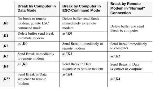
\K – Set Break Control
Defines what action the modem takes when a break (attention signal) is sent or re-ceived, as described below.
Tabel 2 Break Control
Break by Computer in Data Mode Break by Computer in ESC-Command Mode Break by Remote Modem in “Normal” Connection \K0 No break to remote modem; go into ESC command mode
Delete buffer send Break immediately to remote
modem Delete buffer and send Break to computer
\K1 Delete buffer send break
to remote modem
as \K0
\K2 as \K0 Send Break immediately to
remote modem
Send Break immediately to computer
\K3 Send Break immediately
to remote modem
as \K2
as \K2
\K4 as \K0 Send Break in Data
sequence to remote modem
Send Break in Data sequence to computer
\K5*
Send Break in Data sequence to remote modem
as \K4
2-18 AT COMMANDS: DATA MODEM
\N – Set Operating Mode
Determines the type of connection attempted by the modem.
AT\N0,1 Buffer (Normal) Mode – no data compression or error correction, but uses speed buffering.
AT\N2 MNP Reliable Mode – the modem attempts to negotiate an MNP error-correction ’reliable’ link, hanging up if it fails.
AT\N3 V.42 Auto-Reliable Mode – if V.42 detection is enabled (-Jn), a LAPM or MNP link can be detected and negotiated; otherwise, only LAPM is attempted. If configured for -J0 and a protocol con-nection is not made, the modem hangs up. If configured for -J1 and a protocol connection is not made, the modem falls back to speed buffering mode..
AT\N4 V.42 Reliable Mode – the modem attempts to negotiate LAPM error correction, hanging up if it fails
=> Some types of modem will not accept an MNP connection. In such cases, use
the \N0 command (Buffering) or the \N1 command (Direct mode).
\Q – Set Serial Port Flow Control
This command specifies the DTE-to-modem flow control. Software flow control uses the XOFF (13h) command to stop and the XON (11h) characters to start data transmission, both to and from DTE. Undirectional hardware flow control uses the CTS control line to stop or start data from the DTE only, while bidirectional hard-ware flow control also uses the RTS control to stop or start data from the modem.
AT-Q0 Disables flow control
AT-Q1 XON/XOFF software flow control
AT-Q2 Undirectional hardware flow control – CTS
AT-Q3 Bidirectional hardware flow control – RTS/CTS
=> The advantage of the RTS/CTS-Hardware flow control in opposite of the XON/
XOFF Software flow control is the short reactiontime. The reactiontime is for the binary date transfer, which can contain XON/XOFF-settings, absolute ne-cessary.
\T – Set Inactivity Timer
During a buffer (normal) or reliable connection, if no data is sent or received wi-thin the inactivity time period, the link is disconnected. The default, ’0’, disables this feature.
AT\T0-90 Length in minutes
AT\T0 Disables inactivity timer (factory setting) \X – Set XON/XOFF Pass Through
If software flow control is enabled (\Q1), this command defines whether the XON (11h) and XOFF (13h) characters received from the DTE are sent to remote mo-dem. In addtion, if the modem port flow control is enabled (\G1) in normal mode, the command specifies whether the XON and XOFF characters received from the remote modem are sent to the DTE. In both cases, flow control operation is not af-fected.
AT\X0 Processes flow control characters (factory setting)
AT\X1 Processes flow control characters and passes them through to the local or remote so they can process the characters.
-J — Set V.42 Detect Phase
In V.42 modes (\N3, \N4) this command specifies whether the modem detects V.42, MNP, or no error-connection protocols from the remote modem and changes to the appropriate mode. Otherwise, only V.42 is attempted.
AT-J0 Disables V.42 detect phase
AT-J1 Enables V.42 detect phase (factory setting)
%C – MNP 5 Data Compression Control
This command controls whether the data sent during the MNP frames is compres-sed using MNP Class 5 compression standard. MNP 5 data compression can im-prove throughput by as much as 150%.
AT%C0 No compression
AT%C1 MNP Class 5 compression (factory setting)
=> Where files selected for transmission are compressed, the speed of
2-20 AT COMMANDS: DATA MODEM
%E – Auto-Retrain Control
This command controls whether the modem automatically initiates a modem re-train whenever the received data signal quality falls below a threshold that may af-fect data reliability. The value for ’n’ is stored in the NVRAM.
AT%E0 Disabled
AT%E1 Enabeled (factory setting) %G — Rate Renegotiation
This command selects whether the modem automatically initiates a change to higer speed or lower speed depending on received signal quality (that is, rate nego-tiation). The modem always responds to any rate change initiated by the remote modem.
AT%G0 Disabled
AT%G1 Enabled (factory setting) "H — V.42 bis Compression Control
This command specifies whether the data in the LAPM frames are compressed using V.42 bis data compression. This can improve thourghput by as much as 400%. Compression can be negotiated to operate in one direction or both.
AT"H0 Disables V.42 bis
AT"H1 Enables V.42 bis only when transmitting data
AT"H2 Enables V.42 bis only when receiving data
AT"H3 Enables V.42 bis for both transmitting and receiving data (factory setting)
"O — V.42 bis String Length
This command specifies the maximum number of characters that can be compes-sed into one V.42 bis code word. The default value of 32 optimizes throughput for most file types. (6-250 = Number of characters); (n=32; usual number of charac-ters).
Chapter 3
MODEM MESSAGES
The modem responds to AT commands with Modem Messages. You can control their format with the V command verbal (ATV1) or numeric (ATV0).
In addition, the modem issues Connection Messages, when it recognizes activi-ties on the telephone line. The X command determines which messages are autho-rised here.
Messages regarding Modulation, Error correction, Datacompression and Data rate are controlled via the W3-command. The following table gives an overview of the pos-sible messages.
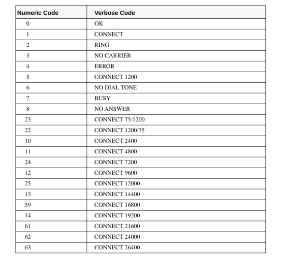
Table 3 DTE-Modem Data Rate Response Codes
Numeric Code Verbose Code
0 OK 1 CONNECT 2 RING 3 NO CARRIER 4 ERROR 5 CONNECT 1200 6 NO DIAL TONE 7 BUSY 8 NO ANSWER 23 CONNECT 75/1200 22 CONNECT 1200/75 10 CONNECT 2400 11 CONNECT 4800 24 CONNECT 7200 12 CONNECT 9600 25 CONNECT 12000 13 CONNECT 14400 59 CONNECT 16800 14 CONNECT 19200 61 CONNECT 21600 62 CONNECT 24000 63 CONNECT 26400
3-2 MODEM MESSAGES Note:
This verbose response code is used to evaluate the modem connection and is en-abled by the W3 AT command. All other ’CONNECT’ messages are used for
W0-W2 AT commands. When the modem is configured for text response V1, the W3
verbose response codes provide information about the DTE data rate, connection modulation, error correction protocol, data compression, and modem-to-modem data rate. When the modem is configured for W3 and numeric responses V0, the modem responds as if set up for W0.
Numeric Code Verbose Code
64 CONNECT 28800 65 CONNECT 31200 33 CONNECT 33333 66 CONNECT 33600 34 CONNECT 37333 28 CONNECT 38400 35 CONNECT 41333 36 CONNECT 42666 37 CONNECT 44000 38 CONNECT 45333 39 CONNECT 46666 42 CONNECT 48000 43 CONNECT 49333 53 CONNECT 50666 54 CONNECT 52000 55 CONNECT 53333 56 CONNECT 54666 57 CONNECT 56000 58 CONNECT 57333 18 CONNECT 57600 31 CONNECT 115200 45 RINGBACK
See Note CONNECT (DTE data rate) / (modulation) / (error correction) / (data compression) / TX: (DCE transmit data rate) /
Chapter 4
S-REGISTERS
The modem has a series of S-Registers, in which the active configuration are stored. The contents of some Registers are stored in a non-volatile memory (NVRAM), which can be interrogated with Z, &Y and &W commands. The syntax for entering and requesting Register values is given in the description of the S command. The va-lues of most of the Registers can be modified by using AT commands.
Table 4 S-Registers (Summary)
Register Range Default. Description
S0* 0-9 ring characters 0 Ring characters before modem answers S1 - 0 Ring character counter
S2* 0-127 ASCII 43 Esc sequence character S3 0-127 ASCII 13 Carriage return character S4 0-127 ASCII 10 Line feed character S5 0–127 ASCII 08 Backspace character S6* 3–6 sec 3 Dial tone waiting time
S7* 1–255 sec 60 Waiting time for carrier after dialling S8* 0–10 sec 2 Pause character comma
S9* 1–255 1/10 sec 6 Answer time after carrier recognition S10* 1–99 1/10 sec 14 Delay: carrier loss to “hanging up” S12* 0-255 1/50 sec 50 Guard time for Esc sequence S14 Bit-mapped 138 (8Ah) General options
S16 Bit-mapped 0 Modem test options S18* 0–255 sec 0 Test Timer S21 Bit-mapped 48 (30h) V.24/General options S22 Bit-mapped 102 (60h) Loudspeaker/modem messages S23 Bit-mapped - General options
S25* 0–255 sec; 1/100 sec 5 DTR delay time S27 Bit-mapped 64 (40h) General options
S30* 0–90 sec 0 Inactivity timer for “hanging up” S33* 0–255 sec 0 Sleep Mode Timer
S37 0 - Type of modulation (Line-Speed) *Register values are stored with &W in the non-volatile NVRAM memory
4-2 S-REGISTERS
S0 – Number of Ring Characters before Modem engages
If S0-Register is set to S0 = 0, automatic answering is switched OFF and the modem does not go on-line. If S0 = 1, the modem will go on-line at the first rin-ging sign, or character.
Range: 0-9 ringing characters; factory setting: 0 S1 – Ring Character Counter
The value of this Register is increased by 1 with each ring which is recognized. It is deleted when pauses exceed 11s.
Range: 0-255 ring characters; factory setting: 0 Read only register
S2 – Esc Sequence Character
ASCII value of the character defined as the Esc sequence, to change from data mode to command mode. The Esc sequence is switched off where this value exceeds 127.
Range: 0-255; factory setting: 43 (ASCII+, “plus” sign) S3 – Carriage Return Character
ASCII value of the Carriage Return character (<CR>Carriage Return) ends the command lines and modem messages.
Range: 0-127; factory setting: 13 (ASCII CR, Carriage Return) S4 – Line Feed Character
ASCII value of the Line Feed character (<LF> Line Feed). The modem sends this character after <CR> to finish verbal modem messages in asynchronous operating mode.
Range: 0-127; factory setting: 10 (ASCII LF, Line Feed) S5 – Backspace Character
ASCII value for Backspace. Entering this will delete the character to the left of the cursor (and the last character in the command memory) and the cursor moves one space backwards.
Range: 0-127, factory setting: 8 (ASCII Backspace) S6 – Waiting Time for Dial Tone
The value of the S6 Register determines when the modem will begin to dial after “going off-hook” (or after recognizing the W parameter in Dialling command mode). The X command controls the effect of the S6 Register. For X0, X1 or X3, the modem waits for the specified period, even if the dial tone occurs earlier. You
can enter any value between 0 and 255 sec in this Register; however, the modem will always remain in the allowed range.
Range: 3–6 seconds; factory setting: 3 sec S7 – Waiting for Carrier Signal
Where the extended mode commands X3 or X4 are active (X3 is the factory setting), the modem waits in Originate mode until the “Free” character is recognized (the other connection is being called). The value of the S7 Register determines the duration of the waiting period. In addition, the value of the S7 Register also determines how long the modem will wait for a carrier signal from the remote modem, before it “hangs up”. Since the modem also waits for a carrier signal, if it does not recognize a “Free” tone, the total waiting time can be twice as long as the value set in the S7 Register.
When answering, the Register value represents only the waiting time for carrier-tone recognition, since the “Free” character is of no importance here. Further, the value of the S7 Register determines the waiting time for a subsequent dialling tone (with no affect on the waiting time after the modem has “lifted the handset”), where the W parameter is in Dial command mode. The subsequent dialling tone is used in telephone systems, where a number is dialled beforehand to call the exchange.
Range: 0-255 sec; factory setting: 60 sec S8 – Pause Time after Comma
If a comma is included in the Dial command, the modem will pause when dialling, when it reaches this character. The length of this pause is determined by S8.
Range: 0-10 sec; factory setting: 2 sec
S9 – Answer Time after Carrier Recognition
The period of time, during which the carrier from the remote station must be present, before the modem goes on-line. A higher value decreases the risk of an incorrect interpretation.
Range: 1-255 1/10 sec; factory setting: 6 (0.6 s)
S10 – Delay between Carrier Loss and Hanging Up
The period of time, during which the modem waits after carrier loss, before it “hangs up”. This allows for a temporary loss of the carrier. The value must be greater than the value of the S9 Register, so that the modem does not “hang up” before recognizing the carrier.
4-4 S-REGISTERS
S12 – Guard Time for Esc Sequence
The Guard Time is the period of time during which, both before and after entering the Esc sequence (+++), the modem is not permitted to receive any characters. Where the Register value is zero, the modem will always go into Command mode after three consecutive Esc signs.
Range: 0; 20 to 255 sec; interval 20 ms, Factory setting: 50 (1 sec) S14 – General Options
Factory setting:138 (8Ah) (10001010b), Read only register
Bit 0 Reserved
Bit 1 Command echo (E-command) 0 Echo OFF (E0)
1 Echo ON (E1)(factory setting)
Bit 2 Modem messages (Q-command)
0 Modem messages ON (Q0) (factory setting) 1 Modem messages OFF (Q1)
Bit 3 Modem messages, verbal/numeric (V-command) 0 Numeric modem messages (V0)
1 Verbal modem messages (V1) (factory setting)
Bit 4 Reserved
Bit 5 Pulse or Tone dialling (P and T dialling parameters) 0 Tone dialling (T)
1 Pulse dialling (P) (factory setting)
Bit 6 Reserved
Bit 7 Originate/Answer mode (A-, D-commands)
0 Answer mode
S16 – Modem Test Options Factory setting: 0; Read only register
Bit 0 Local analogue test loop 0 OFF (factory setting) 1 ON (&T1)
Bit 1 Reserved
Bit 2 Local digital test loop 0 OFF (factory setting)
1 ON
Bit 3 Status of remote digital test loop 0 OFF (factory setting)
1 ON (&T6)
Bit 4 Status of a remote digital test loop, disengaged by the remote modem
0 OFF (factory setting)
1 ON
Bit 5 Remote digital test loop with Self-Test 0 OFF (&T5) (factory setting)
1 ON (&T7)
Bit 6 Local analogue test loop with Self-Test 0 OFF (factory setting)
1 ON &T8)
Bit 7 Reserved
S18 – Test Timer
This determines the duration of a test loop, disengaged by &Tn. Where the Regi-ster value is zero, test loops must be ended with &T0 or with the H-command.
Range: 0-255 sec; factory setting: 0 S21 – V.24/General Options
Factory setting : 48 (30h) (00110000b); Read only register
Bit 0,1,2 Reserved
Bit 3,4 Condition of Control Line DTR
0 &D0
1 &D1
2 &D2 (factory setting)
3 &D3
Bit 5 Condition of Control Line DCD (M5) 0 (&C0)
4-6 S-REGISTERS
1 (&C1) (factory setting)
Bit 6 Condition of Control Line DSR (M1) 0 (&S0) (factory setting)
1 (&S1)
Bit 7 Long Space Disconnect 0 (Y0) (factory setting)
1 (Y1)
S22 – Loudspeaker/Authorised Modem Messages Factory setting : 102 (66h) (01100110b); Read only register
Bit 0,1 Volume
0 Low (L0)
1 Low (L1)
2 Medium (L2) (factory setting)
3 Loud (L3)
Bit 2,3 Loudspeaker Condition 0 Always OFF (M0)
1 OFF after carrier recognition (M1) (factory setting) 2 Always ON (M2)
3 ON during Handshake (M3)
Bit 4-6 Authorised modem messages
0 (X0) 4 (X1) 5 (X2) 6 (X3) (factory setting) 7 (X4) Bit 7 Reserved S23 – General Options
Factory setting : - ; Read only register
Bit 0 Authorise a remote digital test loop for remote modem 0 Not authorised (&T5) unchangeable (factory setting)
Bit 1-3 Interface speed
0 0-300 bps 1 1200 bps 2 2400 bps 3 4800 bps 4 7200 bps 5 9600 bps 6 19200 bps 7 Over 38400 bps
Bit 4,5 Parity
0 Even
1 Reserved
2 Odd
3 No parity
Bit 6,7 Guard Tone (country dependend) 0 No Guard Tone (&G0) (factory setting) 1 No Guard Tone 550 Hz (&G1)
2 Guard Tone 1800 Hz (&G2)
S25 – DTR Delay Time
Period of time between the departure of DTR and “hanging up”. In synchronous operational mode, the measurement units are seconds, while in other operational modes they are hundredths of seconds.
Range: 0-255 sec (1/100 sec); factory setting: 5
S27 – General Options
Factory setting : 64 (40h) (01000000b); Read only register
Bit 0–5 Reserved
Bit 6 CCITT/Bell Mode (B) (only at 300 and 1200 bps)
0 CCITT (B0)
1 Bell (B1) (factory setting)
Bit 7 Reserved
S30 – Inactivity Timer
This determines when the modem goes off-line, when no data are being sent or re-ceived. If no Error Correction procedure is active, this Register is reset only by transmitted data. With other procedures, the Register is reset by any data which are recognized. The timer works only in asynchronous mode.
4-8 S-REGISTERS
S33 – Sleep Mode Timer
S33 determines when the modem enters sleep or power-down mode. When enab-led (S33 ≠ 0), the controller enters sleep modem whenever the modem has been in-active for a user-programmable time delay (S33). The modem is considered to be in an inactive state when:
1. No internal processing is being performed
2. No activity occurs between the host and the modem within a specified time pe-riod
3. The modem is off-line
The modem exits sleep mode whenever the host reads or writes to the modem or when a ring signal is detected
Sleep mode is disabled by setting S33 to ‚0‘.
Range: 0-255 sec
S37– Maximum Line Speed Attempted
This S-register selects the maximum line speed allowalbe (that is, the modem atempts to connect at this speed or falls back to a lower speed). Settings for Bn, +MS=m, Nn, and S37 determine the allowable modem connections. S37 provides the same information as the +MS=m <max rate> parameter. Changing the +MS=m <max rate> parameter automatically changes the value of S37. For ex-ample, setting +MS=m <max rate> to 0 sets S37 to 0. Note that S37 has no effect during V.32 bis retraining/rate negotiation
*Current download speeds are limited to 53,333 bps due to the limited power levels of the PSTN
n = 0 DTE Rate n = 1 Reserviert n = 2 Reserviert n = 3 300 n = 4 Reserviert n = 5 1200 n = 6 2400 n = 7 4800 n = 8 7200 n = 9 9600 n = 10 12,000 n = 11 14,400 n = 12 16,800 n = 13 19,200 n = 14 21,600 n = 15 24,000 n = 16 26,400 n = 17 28,800 n = 18 31,200 n = 19 33,600 n = 20 36,000 n = 21 33,333 n = 22 37,333 n = 23 41,333 n = 24 42,666 n = 25 44,000 n = 26 45,333 n = 27 46,666 n = 28 48,000 n = 29 49,333 n = 30 50,666 n = 31 52,000 n = 32 53,333 n = 33 54,666a n = 34 56,000 n = 35 57,333 a.
Appendix
TECHNICAL INFORMATION
GLOSSARY
AAE Automatic Answering Equipment AM Amplitude Modulation
BPS Characters per second
BSC Byte Synchronous Communication (synchronous protocol) DCE Data Communication Equipment
DTE Data Terminal Equipment DPSK Differential Phase-Shift Keying DTE Data Terminal Equipment (= DTE) ETX End of Text
FCS Frame Checking Sequence FM Frequency Modulation FSK Frequency Shift Keying
HDLC High Level Data Link Control (Synchronous Protocol) MFV Multi-Frequency Dialling Procedure (= Tone Dialling)
MNP Microcom Networking Protocol (Process for Error Checking and Data Compression)
oK Upper Channel PM Phase modulation PSK Phase Shift Keying
QAM Quadratic Amplitude Modulation
Retrain Synchronisation of Modem where Line Conditions have changed SDLC Synchronous Data Link Control (synchronous protocol)
STX Start of Text
SYN Synchronous Character uK Lower Channel
Sign Data Frame, made up of Data bits Length Start, Stop and Parity bits
Appendix-2 TECHNICAL INFORMATION
CCITT RECOMMENDATIONS
V.8 Method for initiating a data transfer with the best modulation possible V.21 300 bps, full-duplex, synchronous and asynchronous, 2-point
Fre-quency Shift Keying
V.22 1200 bps with Fallback to 600 bps, full-duplex, synchronous and asynchronous 4-point Frequency Shift Keying
V.22bis 2400 bps with Fallback to 1200 bps, full-duplex, synchronous and asynchronous 16-point Quadratic Amplitude Modulation
V.23 1200/1200 bps in 4-wire operation, 1200/75 bps in 2-wire opera-tion, 600/600 bps in 4-wire operaopera-tion, 75/1200 bps in 2-wire ope-ration, 75/600 bps in 2-wire opeope-ration, 75/75 bps in 2-wire opera-tion, synchronous and asynchronous, Frequency Shift Keying V.24 List of definitions for interface cabling between Data Terminal
Equipment (DTE) and Data Communication Equipment (DCE) V.25 Automatic Call-Answering Equipment and/or Parallel Dialling
Equipment in the public telephone dialling system, using 200 Group interface cabling
V.25bis Automatic Dialling and/or Call-Answering Equipment in the pu-blic telephone dialling system, using 100 Group interface cabling V.26 2400 bps with Fallback to 1200 bps, 4-wire dedicated line, 4-phase
differential modulation
V.26bis 2400 bps with Fallback to 1200 bps, dialling line operation, half-duplex, synchronous, 4-phase differential modulation
V.26ter 2400 bps with Fallback to 1200 bps, dialling and 2-wire dedicated line operation with echo elimination, full-duplex, synchronous, differential phase modulation
V.27 4800 bps with Fallback to 2400 bps, 4-wire dedicated line operation, 8-phase differential modulation, synchronous, half/full-duplex V.27bis 4800 bps with Fallback to 2400 bps, full or half-duplex in 4-wire,
dedicated line operation, 8-phase differential modulation at 4800 bps; 4-phase differential modulation at 2400 bps
V.27ter 4800 bps with Fallback to 2400 bps, dialling line operation, half-duplex; with 8-phase differential modulation at 4800 bps and 4-phase differential modulation at 2400 bps.
V.28 Definition of the electrical characteristics of so-called non-symme-trical polar lines
V.29 9600 bps, dedicated line operation; Fallback to 7200 or 4800 bps. 16-point quadratic amplitude modulation
V.32 9600, 4800 and 2400 bps with Fallback to 4800 bps dialling line; synchronous and asynchronous, echo suppression; 16/32-point quadratic amplitude modulation; differential Trellis Coding and/or non-redundant coding, full-duplex
V.34 28800…14400, 9600, 4800 u. 2400 bps, Fallback to 4800 bps; full-duplex and half-full-duplex
V.Fast Class 28800…14400
V.42bis Error Correction and Data Compression Procedure to CCITT Tabelle A-1 Technical Specifications
Parameter Specifications
Methods of operation Asynchronous with manual and automatic dialling
(AT-commands)
Error Correction and Data
Compression MNP Classes 1–5, V.42 and V.42bis Transmission rates and
Modulation procedure See Chapter 1 Tolerance for deviation from
nominal speed
Max.: +1 (+ 2,3), -2,5%
Character length asynchronous 7, 8, 9, 10, 11 Bits (incl. Star and Stop bits)
Pulse adjustment in synchronous mode
Internal: Local oscillator
Extern: Pulse loop (Receive pulse = send pulse)
Interface with telephone network
Dialling line: 2-wire, full duplex
Digital interface RS232
Automatic dialling DTMF dialling
Loudspeaker Software-controlled: 3 volume levels.
DTMF amplitude fluctuation <1 dB
Tone duration 90 ms
Guard tone 550 Hz, 1800 Hz or no Guard tone
Power supply external power supply
Low-voltage jack: Power consumption 700 mA AC 9V AC Temperature range 0–35 ° C Storage temperature -25–+70 °C
Air humidity max. 85% (Rel.)
Dimensions 135 *152 * 35 mm (L*B*H)
Declaration of Conformity
This declaration is valid for the following device:
V.90 Modem
Hereby we declare that the above mentioned device is conforming to:
Council Directive (89/336/EEC) Council Directive (73/23/EEC) Council Directive (98/13/EC)
The device has been tested in accordance to:
DIN EN 50082:1987 Part 1 DIN EN 55022 DIN EN 60950