Multi-stage Pseudo-static Analysis
GEO-SLOPE International Ltd. | www.geo-slope.com 1400, 633 - 6th Ave SW, Calgary, AB, Canada T2P 2Y5 Main: +1 403 269 2002 | Fax: +1 403 266 4851Introduction
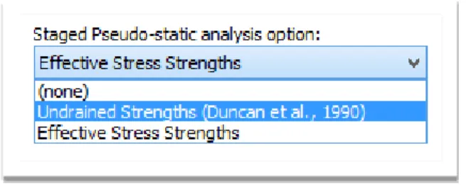
It is generally assumed that during a seismic event the loading is so rapid that there will be no change in the shearing resistance along a potential slips surface. Stated another way, it is generally assumed that the soil will behave in an undrained manner. The seismic loading may increase the total stress at the base of a slice and there may be an equivalent change in the pore-pressure, but the effective stress will remain unchanged, and consequently the strength will remain unchanged. A staged pseudo-static analysis can be completed to give consideration to this scenario. Two options are available for calculating the undrained strengths prior to the application of the seismic forces.
et al. (1990) require both the effective stress strength properties and those corresponding to the undrained R-envelop. These two strength envelops are used to compute an equivalent undrained strength at the base of each slice. The “None” option results in a conventional, single stage, pseudo-static analysis (Figure 1).
Figure 1. Dropdown menu for selecting the staged pseudo-static option for calculating strengths.
Example problem
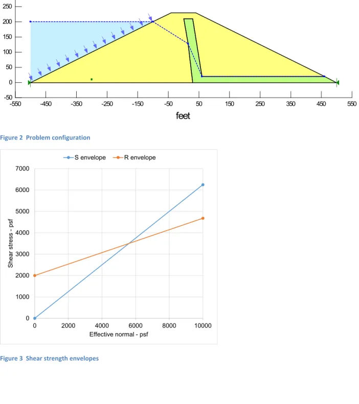
Several examples were created in association with the development of the UTEXAS slope stability software package. One of the examples (Example M) was created to illustrate a staged pseudo-static stability analysis. The example configuration is shown in Figure 2.
The domain represents a 230-foot high water retention embankment with 2:1 side slopes. The fill material is clay. The saturated total unit weight is 135 pcf and the unit weight for the soil above the water table is 132 pcf.
The effective stress shear strength envelope (S) is defined by c = 0.0 and φ = 32ᵒ. The total strength envelope (R) is defined by c = 2000 psf and φ = 15ᵒ. As is evident in Figure 3, the two envelopes cross over at 5600 psf.
One trial slip surface is considered for illustrative purposes (Figure 4). The specified pseudo-static seismic coefficient is 0.2. Four analyses were completed: 1) a conventional analysis excluding seismic forces; 2) a conventional pseudo-static analysis; 3) staged pseudo-static analysis using effective stress strengths; and, 4) staged pseudo-static analysis using undrained strength calculated according to Duncan et al. (1990).
feet
-550 -450 -350 -250 -150 -50 50 150 250 350 450 550 -50 0 50 100 150 200 250 300Figure 2 Problem configuration
0 1000 2000 3000 4000 5000 6000 7000 0 2000 4000 6000 8000 10000 S h e a r st re ss -p sf Effective normal - psf S envelope R envelope
Figure 4 Trial slip surface
Results and Discussion
The factors of safety corresponding to each analysis is: Excluding seismic forces: 1.872
None (conventional pseudo-static): 1.045 Duncan et al. (1990) undrained strengths: 1.088
Effective stress (equivalent undrained) strengths: 1.103
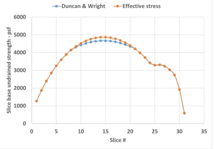
Figure 5 compares the undrained strength from the two staged strength options. The two methods are identical at the lower base normal stress but deviate slightly at higher base normal stresses. The slightly lower strengths over a portion of the slip surface results in a slightly lower factor of safety.
1000 2000 3000 4000 5000 6000 ic e ba se u nd ra in ed st re ng th -ps f
Summary
SLOPE/W has the option to consider an undrained response when doing a pseudo-static analysis. Two methods are available for computing the undrained strengths at the base of each slice. The strengths are calculated in the first stage of the analysis when the seismic forces are excluded. The strengths are then ‘locked in’ for the second stage of the analysis when the seismic forces are included.
The simple effective stress approach requires only the conventional effective stress strength properties. The strength calculations proposed by Duncan et al. (1990) also requires the definition of the total stress (R) strength parameters.
References
Duncan, J.M.,Wright S.G. and Wong, K.S. (1990). “Slope Stability during Rapid Drawdown”. Proceedings of H. Bolton Seed Memorial Symposium. Vol. 2.