784 INTELLIGENT TRANSPORTATION SYSTEMS–NETWORK DEVICES. (REV 10-5-05) (FA 2-1-06) (7-06)
PAGE 755. The following new Section is added after Section 715: SECTION 784
INTELLIGENT TRANSPORTATION SYSTEMS NETWORK DEVICES
784-1 Managed Field Ethernet Switch.
784-1.1 Description. Furnish and install a hardened, device-level managed field Ethernet switch (MFES) for intelligent transportation system (ITS) projects. Ensure that the MFES
provides wire-speed fast Ethernet connectivity at transmission rates of 100 megabits per second from the remote ITS device installation location to the ITS network trunk interconnection point. 784-1.2 Materials:
784-1.2.1 General: Ensure that the ITS network administrator will be able to manage each MFES individually or as a group/cluster for switch configuration, performance monitoring, and troubleshooting. These specifications require additional minimum management intelligence (i.e., Layer 2+) typical of most current industrial Ethernet deployments. Ensure that the MFES includes Layer 2+ capability providing architecture standardization, open connectivity (i.e., interoperability), bandwidth management, rate limiting, security filtering, and general integration management of an advanced Ethernet switching architecture.
Ensure that the furnished MFES is fully compatible and interoperable with the ITS trunk Ethernet network interface, and that the MFES supports half and full duplex
Ethernet communications.
Furnish an MFES that provides 99.999% error-free operation, and that complies with the Electronic Industries Alliance (EIA) Ethernet data communication
requirements using single-mode fiber optic transmission medium and Category 5E copper transmission medium. Provide a switched Ethernet connection for each remote ITS field device.
Ensure that the MFES has a minimum mean time between failures (MTBF) of 10 years, or 87,600 hours, as calculated using the Bellcore/Telcordia SR-332 standard for reliability prediction.
784-1.2.2 Networking Standards: Ensure that the MFES complies with all applicable IEEE networking standards for Ethernet communications, including but not limited to:
1. IEEE 802.1D standard for media access control (MAC) bridges used with the Spanning Tree Protocol (STP).
2. IEEE 802.1Q standard for port-based virtual local area networks (VLANs).
3. IEEE 802.1P standard for Quality of Service (QoS).
4. IEEE 802.1w standard for MAC bridges used with the Rapid Spanning Tree Protocol (RSTP).
5. IEEE 802.1s standard for MAC bridges used with the Multiple Spanning Tree Protocol.
6. IEEE 802.3 standard for local area network (LAN) and metropolitan area network (MAN) access and physical layer specifications.
7. IEEE 802.3u supplement standard regarding 100 Base TX/100 Base FX.
8. IEEE 802.3x standard regarding flow control with full duplex operation. 784-1.2.3 Optical Ports: Ensure that all fiber optic link ports operate at 1,310 or 1,550 nanometers in single mode. Verify that the optical ports are Type ST, SC, LC, or FC only, as specified in the plans or by the Engineer. Do not use mechanical transfer registered jack (MTRJ) type connectors.
Provide an MFES having a minimum of two optical 100 Base FX ports capable of transmitting data at 100 megabits per second. Each optical port shall consist of a pair of fibers; one fiber will transmit (TX) data and one fiber will receive (RX) data. The optical ports shall have an optical power budget of at least 15 dB.
784-1.2.4 Copper Ports: Provide an MFES that includes a minimum of four copper ports. All copper ports shall be Type RJ-45 and shall auto-negotiate speed (i.e., 10/100 Base) and duplex (i.e., full or half). All 10/100 Base TX ports shall meet the specifications detailed in this section and shall be compliant with the IEEE 802.3 standard pinouts.
All Category 5E unshielded twisted pair/shielded twisted pair network cables shall be compliant with the EIA/TIA-568-A standard.
784-1.2.5 Management Capability: Ensure that the MFES supports all Layer 2 management features and certain Layer 3 features related to multicast data transmission and routing. These features shall include, but not be limited to:
1. An STP healing rate that meets or exceeds specifications published in the IEEE 802.1D standard.
2. An RSTP healing rate that meets or exceeds specifications published in the IEEE 802.1w standard.
3. An MFES that is a port-based VLAN and supports VLAN tagging that meets or exceeds specifications as published in the IEEE 802.1Q standard, and has a minimum 4-kilobit VLAN address table.
4. A forwarding/filtering rate that is a minimum of 14,880 packets per second for 10 megabits per second and 148,800 packets per second for 100 megabits per second.
5. A minimum 4-kilobit MAC address table.
6. Support of Traffic Class Expediting and Dynamic Multicast Filtering. 7. Support of, at a minimum, Version 2 of the Internet Group Management Protocol (IGMP).
8. Support of remote and local setup and management via telnet or secure Web-based GUI and command line interfaces.
9. Support of the Simple Network Management Protocol (SNMP). Verify that the MFES can be accessed using the resident EIA-232 management port, a
telecommunication network, or the Trivial File Transfer Protocol (TFTP).
10. Port security through controlling access by the users. Ensure that the MFES has the capability to generate an alarm and shut down ports when an unauthorized user accesses the network.
11. Support of remote monitoring (RMON) of the Ethernet agent and the ability to be upgraded to switch monitoring (SMON), if necessary.
12. Support of the TFTP, the Network Time Protocol (NTP), or the Simple Network Time Protocol (SNTP). Ensure that the MFES supports port mirroring for
784-1.2.6 Mechanical Specifications: Ensure that all wiring complies with NEC requirements and standards. Furnish and identify all equipment and appurtenances by name, model number, serial number, technical support and warranty telephone numbers, and any other pertinent information required to facilitate equipment maintenance.
Ensure that every conductive contact surface or pin is gold-plated or made of a noncorrosive, nonrusting, conductive metal.
Ensure that all external screws, nuts, and locking washers are stainless steel. Do not use self-tapping screws unless the Engineer provides prior approval.
All parts shall be made of corrosion-resistant materials, such as plastic, stainless steel, anodized aluminum, brass, or gold-plated metal.
784-1.2.7 Electrical Specifications: Ensure that the MFES operates and power is supplied with 115 volts of alternating current (VAC). Ensure that the MFES has a minimum
operating input of 85 VAC and a maximum operating input of 265 VAC. If the device requires
operating voltages other than 120 VAC, supply the required voltage converter. Ensure that the
maximum power consumption does not exceed 50 watts.
Ensure that the MFES has diagnostic light emitting diodes (LEDs), including link, TX, RX, speed (for Category 5E ports only), and power LEDs.
784-1.2.8 Environmental Specifications: Ensure that the MFES performs all of the required functions during and after being subjected to an ambient operating temperature range of -30 degrees (°) to 165° Fahrenheit (F) as defined in the environmental requirements section of the NEMA TS 2 standard, with a noncondensing humidity of 0 to 95%.
Verify that the MFES manufacturer certifies their device has successfully completed environmental testing as defined in the environmental requirements section of the NEMA TS 2 standard. Verify that vibration and shock resistance meet the requirements of Sections 2.1.9 and 2.1.10, respectively, of the NEMA TS 2 standard.
Ensure that the MFES is protected from rain, dust, corrosive elements, and typical conditions found in a roadside environment.
784-1.3 Installation Requirements: Mount the MFES inside a field site cabinet. Ensure that the MFES is resistant to all electromagnetic interference (EMI). Ensure that the MFES is mounted securely in 19 inches EIA racking and is fully accessible by field technicians.
Due to the nature of the equipment, complexity of the electronics, and harsh environmental conditions at installation locations, use MFES units that can be serviced or replaced immediately when defective or damaged units must be removed and replaced. The Department shall return damaged units to the manufacturer for warranty repair or replacement. 784-1.4 Testing:
784-1.4.1 General: Subject the MFES to design approval tests (DATs) and field acceptance tests (FATs). Develop and submit a test plan for DATs and FATs to the Engineer for consideration and approval.
The Engineer may accept certification by an independent testing
laboratory in lieu of the DATs to satisfy the requirement that certain features and functions have been witnessed and documented as performing satisfactorily. The Contractor shall arrange for and conduct the tests and is responsible for satisfying all inspection requirements prior to submission for the Engineer’s inspection and acceptance.
The Engineer reserves the right to witness all DATs and FATs. Complete the tests within five calendar days.
784-1.4.2 Transient, Temperature, Voltage, and Humidity Testing: The selected manufacturer will provide two MFES units for testing and evaluation purposes at no cost to the Department. The units shall be tested and evaluated as indicated below.
The Department’s Traffic Engineering Research Laboratory (TERL), or another independent testing facility of the Engineer’s choice, shall test the units. The TERL shall perform the test procedures as noted within Section 2.2.7 of the NEMA TS 2-1998standard and shall include the following tests:
1. Test A: (DAT) Placement in Environmental Chamber and Check-Out of Hook-Up.
2. Test B: (DAT) Temperature Cycling and Applied Transient Tests (Power Service).
3. Test C: (DAT and Production Testing) Temperature Low-Voltage Tests.
4. Test D: (DAT and Production Testing) Low-Temperature High-Voltage Tests.
5. Test E: (DAT and Production Testing) Temperature High-Voltage Tests.
6. Test F: (DAT and Production Testing) High-Temperature Low-Voltage Tests.
7. Test G: Test Termination (All Tests). 8. Test H: Appraisal of Equipment under Test.
784-1.4.3 Field Testing: Once the MFES has been installed, conduct local FATs at the MFES field site according to the submitted test plan. Perform the following:
1. Verify that physical construction has been completed as detailed in the plans.
2. Inspect the quality and tightness of ground and surge protector connections.
3. Verify proper voltages for all power supplies and related power circuits. 4. Connect devices to the power sources.
5. Verify all connections, including correct installation of communication and power cables.
6. Verify configuration of the MFES Internet Protocol (IP) addresses and subnetwork mask.
7. Verify the network connection to the MFES through ping and telnet sessions from a remote personal computer (PC).
8. Perform testing on multicast routing functionality. 784-2 Device Server.
784-2.1 Description. Furnish and install a device server as shown in the plans. Provide a device server that includes a central processing unit (CPU), realtime operating system (RTOS), Transmission Control Protocol/Internet Protocol (TCP/IP) stack, and Ethernet and serial data ports to allow connection of serial devices with EIA-232, EIA-422, and EIA-485 connections to an Ethernet network. Ensure that the device server (also referred to as a terminal server)
encapsulates serial data in network packets and transports them across IP networks. 784-2.2 Materials:
784-2.2.1 General: Ensure that the device server provides a TCP/IP interface to one or more field devices using EIA-232/422/485 standard connections. Ensure that the device
server supports TCP/IP, User Datagram Protocol (UDP)/IP, Dynamic Host Configuration Protocol (DHCP), Address Resolution Protocol (ARP), Internet Control Message Protocol (ICMP), Simple Network Management Protocol (SNMP), Hypertext Transfer Protocol (HTTP), and telnet.
Ensure that the device server provides 99.999% error-free operation and EIA-compatible Ethernet data communication by way of a Category 5E copper or fiber optic transmission medium, as shown in the plans.
Ensure that the device server is resistant to all electromagnetic interference.
Use a device server having an encryption feature that provides data security and prevents interception or “sniffing” of transmitted information by unauthorized parties. Data security shall comply with Version 2 of the Secure Shell Protocol (SSHv2), or the NIST requirements as defined in the Federal Information Processing Standard (FIPS)
Publication (PUB)-197 for the Advanced Encryption Standard (AES).
Ensure that the device server has a minimum mean time between failures (MTBF) of 10 years, or 87,600 hours.
784-2.2.2 Serial Interface: Ensure that the device server provides a minimum of one serial data interface and connector as specified in the plans that conforms to
EIA-232/422/485 standards. Ensure that the device server supports 2-wire and 4-wire EIA-485 connections. Ensure that the device server serial port(s) support data rates up to 230 kbps; error detection procedures utilizing parity bits (i.e., none, even, odd, mark, and space); and stop bits (1 or 2).
Ensure that the device server provides flow control (request to send [RTS]/clear to send [CTS] and transmit on/transmit off [XON/XOFF]), as well as allow control of the data terminal ready (DTR), data carrier detect (DCD), data set ready (DSR), CTS, and RTS signals. Ensure that the device server supports RTS toggle for half-duplex emulation.
784-2.2.3 Network Interface: Ensure that the device server includes a minimum of one Ethernet port, which must provide a 10/100 Base-TX or a 10/100 Base-FX connection as specified in the plans. Verify that all Category 5E, unshielded twisted pair/shielded twisted pair network cables and connectors comply with the EIA and Telecommunications Industry
Association (TIA) requirements as detailed in the EIA/TIA-568-A standard. Verify that all copper-based network interface ports utilize registered jack (RJ)-45 connectors. Provide fiber optic cable and connectors for fiber optic cable compliant with Section 783.
784-2.2.4 Configuration and Management: Provide a device server that
supports local and remote configuration and management, which must include access to all user-programmable features, including but not limited to addressing, port configuration, device monitoring, diagnostic utilities, and security functions. Ensure that the device server supports configuration and management via serial login, SNMP, telnet login, and browser-based interface.
784-2.2.5 Mechanical Specifications: Ensure that all parts are made of
corrosion-resistant materials, such as plastic, stainless steel, anodized aluminum, brass, or gold-plated metal. Ensure that all exposed fasteners are stainless steel.
Ensure that the dimensions of the device server accommodate the unit’s installation in a control cabinet as specified in the plans.
784-2.2.6 Electrical Specifications: Verify that all wiring meets applicable NEC requirements and that the device server operates using a nominal input voltage of 120 volts alternating current (VAC). The input voltage range shall be 89 to 135 VAC. If the device requires
nominal input voltage of less than 120 VAC, furnish the appropriate voltage converter. Verify that
the maximum power consumption does not exceed 12 watts.
Ensure that the device server includes diagnostic status indicators in the form of light emitting diodes (LEDs) that provide link, transmit (TX), receive (RX), and power status information.
784-2.2.7 Environmental Specifications: Verify thatthe device server meets all specifications and is capable of performing all of its functions during and after being subjected to an ambient operating temperature range of -31 degrees (°) to 165° Fahrenheit (F), as required in the NEMA TS 2 standard, with a noncondensing relative humidity of 0% to 95%.
Install the device server in an enclosure that provides protection from moisture and airborne contaminants, blowing rain, wind, blowing dust, temperature, humidity, roadside pollutants, vandalism, pests, and theft of equipment.
Verify that the device server meets the vibration and shock resistance specifications as provided in Section 2.1.9 and 2.1.10, respectively, of the NEMA TS 2 standard.
784-2.3 Installation Requirements: Install all equipment and software according to the manufacturer’s recommendations or as directed by the Engineer. Mount the device server securely in a location in the equipment cabinet that allows the unit to be fully accessible by field technicians.
Due to the nature of the equipment, complexity of the electronics, and harsh environmental conditions at installation locations, use device servers that can be replaced immediately when defective or damaged units must be removed and replaced. The Department shall return damaged units to the manufacturer for warranty repair or replacement.
784-2.4 Device and Subsystem Testing:
784-2.4.1 Contractor Test Results: Supply documentation of all test results to the Engineer prior to approval of the system.
In lieu of or in addition to the above, the Engineer may consider outside contractor and third party test results.
784-2.4.2 Environmental Testing: Provide two device servers for testing and evaluation purposes at no cost to the Department. The servers shall be tested and evaluated as specified in this section.
784-2.4.2.1 Transient, Temperature, Voltage, and Humidity Test Specifications: The Department’s Traffic Engineering Research Laboratory (TERL), or an independent testing facility of the Engineer’s choice, shall test the device servers. The testing shall be performed according to the procedures in Section 8.7of the NEMA TS 2 standard and shall include:
1. Test A: (DAT) Placement in Environmental Chamber and Check-Out of Hook-Up.
2. Test B: (DAT) Temperature Cycling and Applied Transient Tests (Power Service).
3. Test C: (DAT and Production Testing) Temperature Low-Voltage Tests.
4. Test D: (DAT and Production Testing) Low-Temperature High-Voltage Tests.
. 5. Test E: (DAT and Production Testing) Temperature High-Voltage Tests.
6. Test F: (DAT and Production Testing) High-Temperature Low-Voltage Tests.
7. Test G: Test Termination (All Tests). 8. Test H: Appraisal of Equipment under Test.
784-2.4.2.2 Field Test Requirements: Perform local field operational tests at device server field sites according to the test procedures stated herein.
1. Verify that physical construction has been completed as specified in the plans.
2. Verify the quality and tightness of ground and surge protector connections.
3. Verify proper voltages for all power supplies and related power circuits.
4. Connect devices to the power sources.
5. Verify all connections, including correct installation of communication and power cables.
6. Verify the network connection to the device server through ping and telnet session from a remote personal computer (PC).
7. Verify serial data transmission through the device server. 784-3 Digital Video Encoder and Decoder.
784-3.1 Description: Furnish and install digital video encoder (DVE) and digital video decoder (DVD) hardware and software to create a video-over-IP network system, as shown in the plans, and as directed by the Engineer.
784-3.2 Materials:
784-3.2.1 General: Use DVEs and DVDs that are specialized network-based hardware devices and software which allow video and data signals to be encapsulated and
transmitted across IP networks. Ensure that the video and data packets produced by the DVE and placed onto the network allow reconstruction of digital video signals by hardware-based and software-based DVDs that are also attached to the network.
Ensure that the complete video and data transmission system, defined as the combination of DVE and DVD hardware together with the existing or planned network infrastructure, simultaneously transports video and data from multiple remote field locations to multiple monitoring locations for roadway surveillance and traffic management. Ensure that end-to-end transmission of 30 frames-per-second (fps) D1 resolution video and data signals from DVE inputs to DVD outputs occurs within 250 milliseconds.
784-3.2.2 Software: Provide a software decoding and control package that allows the viewing of any video source connected to the network through a DVE, and which allows the pan-tilt-zoom (PTZ) control of any PTZ camera on the network, the discovery of DVE and DVD devices on the network, and the control and adjustment of programmable parameters in the DVE and DVD equipment, including the network addresses of these devices, at no additional cost.
Provide all setup, control programs, and diagnostic software related to the DVE or DVD. Provide all equipment licenses, where required for any software or hardware in the system. Ensure that the DVE and DVD are compatible with the Department’s SunGuideSM Software System.
784-3.2.3 Format: Furnish DVE and DVD components that utilize the Moving Picture Experts Group’s MPEG-2 video compression technology in accordance with the International Organization for Standardization (ISO) and International Electrotechnical
Commission (IEC) requirements detailed in the ISO/IEC 13818 standard. Ensure that the DVE and DVD are capable of unicast and multicast operation, and that they support the Session Announcement Protocol (SAP) as recommended by the Internet Engineering Task Force (IETF) RFC 2974, and Differentiated Services/Quality of Service (DiffServ/QoS) software components. Ensure that the DVE provides 99.999% error-free operation.
The Department shall consider the introduction, and possible use, of maturing MPEG-4 and H.264 video compression technologies as an alternate to MPEG-2 if the proposed device meets all requirements herein, excluding MPEG-2 specifics, and provided that the device is interoperable with the Department’s SunGuideSM software. The Department may require certification of compliance with these specifications by an independent technical laboratory. The cost of this certification shall be the responsibility of the Contractor. 784-3.2.4 Digital Video Encoder: Provide a DVE that is a hardware-based network device able to accept a minimum of one analog National Television System Committee (NTSC) video input and digitize it for transport across IP networks. Use a DVE that provides a minimum of two serial data interfaces for transmission of command and control data to other devices (typically camera PTZ commands), as well as console and configuration functions. Provide compatible decoder software along with the DVE at no additional cost, as shown in the plans, or as directed by the Engineer.
784-3.2.5 Digital Video Decoder: Provide a DVD that is either a hardware-based network device or a software application that resides on a workstation personal computer (PC).
784-3.2.5.1 Hardware-based Decoder: Provide a hardware-based decoder that has a minimum of one analog NTSC video output and decodes digital video and data streams present on an IP network into analog formats for interconnection with other devices. Use a DVD that has a minimum of two serial data interfaces for transmission of command and control data to other devices, as well as console and configuration functions. Use a DVD that includes an Ethernet interface for connection to IP networks.
784-3.2.5.2 Software-based Decoder: Provide a software-based DVD that is compatible with the Department’s SunGuideSM software. Ensure that any software-based decoder applications do not interfere with SunGuideSM software operating when installed and used together on a shared hardware platform. Ensure that the software application provides PC desktop display of IP network video streams and control of any PTZ camera connected to the network. The decoder and PTZ functions may be achieved through the use of discrete software applications. Ensure that the software-based decoder offers an open API and software
development kit available to the Department at no cost for integration with third party software and systems.
784-3.2.6 Interoperability: Provide DVE and DVD devices and software that are interoperable and interchangeable with DVE and DVD devices and software from other manufacturers. Ensure that the DVE is compatible and fully interoperable with software and hardware DVDs from the DVE manufacturer, as well as a minimum of two software and hardware DVDs from other manufacturers. Ensure that the DVD is compatible and fully
interoperable with DVEs from the DVD manufacturer, as well as a minimum of two other DVEs from other manufacturers.
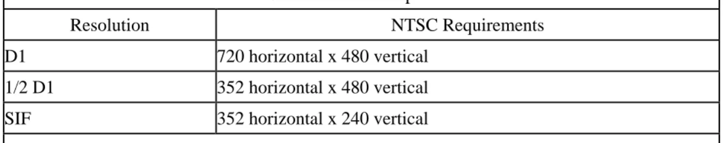
784-3.2.7 Video Specifications: Ensure that any video input utilizes a BNC connector and delivers 1 volt peak-to-peak (Vp-p) NTSC composite video signals for encoding. Ensure that the DVE and DVD operate with both color and monochrome video, and that they allow the user to select and adjust video resolution. Ensure that the DVE and DVD support
resolutions that include, but are not limited to, those defined in Table 3.1. Ensure that the DVE and DVD are capable of delivering color and monochrome video at 30 fps regardless of
resolution, and that they can do so using, programmable bit rates from 128 Kbps to 8 Mbps. Ensure that the DVE provides fixed and variable bit rate modes.
Table 3.1 – Resolution Specifications
Resolution NTSC Requirements
D1 720 horizontal x 480 vertical 1/2 D1 352 horizontal x 480 vertical SIF 352 horizontal x 240 vertical Note: The resolutions attained depend on the data transmission rate.
784-3.2.8 Serial Interface: Use hardware-based DVEs and DVDs having a minimum of two serial data interfaces and connectors that conform to EIA-232/422/485 standards. Ensure that the serial interfaces support 232 as well as 2-wire and 4-wire EIA-422/485 connections. Ensure that the serial port(s) support data rates up to 115.2 Kbps. Serial interface parameters, such as data format, number of bits, handshaking, and parity, shall be software programmable through local connection to the DVE and DVD and through connections over the network. Serial interface ports may utilize RJ-45 connectors, D-sub connectors, or screw terminals.
784-3.2.9 Network Interface: Ensure that the DVE/DVD local area network (LAN) connection supports the requirements detailed in the IEEE 802.3 standard for 10/100 Ethernet connections. Provide a DVE having a minimum of one Ethernet port, which shall be a 10/100 Base-TX connection or a 100 Base-FX ST, SC, LC or FC interface capable of multi-hop configuration using two sets of optical ports (e.g., Tx1, Rx1, Tx2, Rx2). Ensure that the connector complies with applicable EIA and TIA requirements. Provide copper-based network interface ports that utilize RJ-45 connectors. Ensure that all fiber-based ports are single mode and provide a link budget of 30 dB or greater.
Ensure that all Category 5E, unshielded twisted pair/shielded twisted pair network cables are compliant with the EIA/TIA-568-A standard. Ensure that the network
communication conforms to User Datagram Protocol (UDP), Version 4 of the Internet Protocol (IP) and Version 2 of the Internet Group Multicast Protocol (IGMP).
784-3.2.10 Front Panel Status Indicators: Provide DVEs and DVDs that have light-emitting diode (LED) displays, liquid crystal displays (LCDs), or similar illuminated displays to indicate status for power, data activity, link status, and video transmission.
784-3.2.11 Configuration and Management: Provide DVEs and DVDs that support local and remote configuration and management. Configuration and management functions shall include access to all user-programmable features, including but not limited to addressing, serial port configuration, video settings, device monitoring, diagnostic utilities, and security functions. Ensure that the DVE and DVD support configuration and management via serial login, telnet login, and Simple Network Management Protocol (SNMP).
784-3.2.12 Electrical Specifications: Ensure that all wiring meets NEC
alternating current (VAC). The equipment shall operate within a voltage range of 89 VAC to 135
VAC. The operating frequency range for power shall be 60 hertz ±3 Hz. If the device requires
operating voltages of less than 120 VAC, supply the appropriate voltage converter.
784-3.2.13 Environmental Specifications: Except as may be stated otherwise in the plans, provide DVEs and DVDs that meet all specifications during and after being subjected to an ambient operating temperature range of -30 degrees (°) to 165° Fahrenheit (F) [-34° to 74° Celsius (C)] as defined in the environmental requirements section of the NEMA TS 2 standard, with a maximum non-condensing relative humidity of 95%.
Ensure that cabinets housing system components comply with the environmental requirements detailed in the NEMA TS 2 standard. House the DVE in a field cabinet with protection from moisture and airborne contaminants, blowing rain, wind, blowing sand, blowing dust, humidity, roadside pollutants, vandalism, and theft. Ensure that the DVE is resistant to vibration and shock, and conforms to Sections 2.1.9 and 2.1.10, respectively, of the NEMA TS 2 standard.
Ensure that a DVD installed in a climate-controlled environment, such as a TMC computer room, meets all specifications during and after being subjected to an ambient operating temperature range of 32 degrees (°) to 113° Fahrenheit (F) [0° to 45° Celsius (C)].
784-3.3 Installation Requirements: Ensure that the DVE is shelf- and/or
rack-mountable, and designed for use in roadside control cabinets without climate control. Ensure that the dimensions of the DVE allow installation in a control cabinet as specified in the plans. Ensure that front panel status indicators remain unobstructed and visible. Use only stainless steel external screws, nuts, and locking washers. All parts shall be made of corrosion-resistant materials, such as plastic, stainless steel, anodized or painted aluminum, brass, or gold-plated metal.
Because a DVD may be hardware or software-based, these mechanical
specifications apply only to hardware-based DVDs. Field-hardened DVDs shall be shelf- and rack-mountable, and designed for use in roadside control cabinets without climate control. The dimensions of the DVD shall allow installation in a control cabinet as specified in the plans. All external screws, nuts, and locking washers shall be stainless steel. All parts shall be made of corrosion-resistant materials, such as plastic, stainless steel, anodized or painted aluminum, brass, or gold-plated metal.
Non-hardened DVDs shall be shelf- and rack-mountable, and designed for use in a climate-controlled TMC. The rack-mounted DVD shall be designed to fit in a standard EIA 19 inch rack and shall not require shielding from other electronic devices, such as power supplies and other communication equipment. The dimensions of the DVD shall allow installation as specified in the plans.
Due to the nature of the equipment, complexity of the electronics, and harsh environmental conditions at installation locations, use DVEs and DVDs that can be replaced immediately when defective or damaged units must be removed and replaced. The Department shall return damaged units to the manufacturer for warranty repair or replacement.
784-3.4 Device and Subsystem Testing: Supply documentation of all test results to the Engineer prior to approval of the system. In lieu of or in addition to this requirement, the Engineer may consider outside contractor and third party test results.
784-3.4.1 Environmental Testing: Provide two units for environmental testing and evaluation purposes at no cost to the Department. The units shall be tested and evaluated as specified in this section. The FDOT Traffic Engineering Research Laboratory (TERL), or
another independent testing facility of the Engineer’s choice, shall test the DVE and hardened DVD with respect to environmental requirements. The TERL shall perform the test procedures noted in Section 8.7 of the NEMA TS 2 standard, and shall include the following tests:
1 .Test A: (DAT) Placement in Environmental Chamber and Check-Out of Hook-Up.
2. Test B: (DAT) Temperature Cycling and Applied Transient Tests (Power Service).
3. Test C: (DAT and Production Testing) Low-Temperature Low-Voltage Tests.
4. Test D: (DAT and Production Testing) Low-Temperature High-Voltage Tests.
5. Test E: (DAT and Production Testing) High-Temperature High-Voltage Tests.
6. Test F: (DAT and Production Testing) High-Temperature Low-Voltage Tests.
7. Test G: Test Termination (All Tests). 8. Test H: Appraisal of Equipment under Test.
784-3.4.2 Field Test Requirements: Perform local field operational tests at the device field site and end-to-end video streaming tests as required by the Engineer in order to demonstrate compliance with Department specifications. Testing will include, but not be limited to, the following:
1. Verify that physical construction has been completed as detailed in the plans.
2. Inspect the quality and tightness of ground and surge protector connections.
3. Verify proper voltages for all power supplies and related power circuits. 4. Connect devices to the power sources.
5. Verify all connections, including correct installation of communication and power cables.
6. Verify video image is present and free from oversaturation and any other image defect in both color and monochrome mode.
7. Verify network connection to the DVE and DVD through ping and telnet session from a remote PC.
8. Verify serial data transmission through the DVE and DVD serial ports. 9. Verify support of unicast, multicast, SAP, and QoS.
784-4 Guaranty Provisions.
784-4.1 General: Ensure that the balance of the manufacturer’s warranty is fully transferable from the Contractor to the Department.
If the manufacturer’s warranties noted below are for a longer period, those longer period warranties will apply.
784-4.2 MFES: Provide an MFES having a manufacturer’s warranty for equipment and parts furnished to be free from defects in fabrication, assembly, and materials for five years from the date of final acceptance by the Engineer in accordance with 5-11 of all work to be performed under the Contract.
Ensure that the MFES includes technical support for both the product hardware and its software for three years from the date of final acceptance.
784-4.3 Device Server: Provide a device server having a manufacturer’s warranty for equipment and parts furnished to be free from defects in fabrication, assembly, and materials for five years from the date of final acceptance by the Engineer in accordance with 5-11 of all work to be performed under the Contract.
784-4.4 Digital Video Encoder and Decoder: Provide a DVE or DVD having a
manufacturer’s warranty for equipment and parts furnished to be free from defects in fabrication, assembly, and materials for two years from the date of final acceptance by the Engineer in accordance with 5-11 of all work to be performed under the Contract.
784-5 Method of Measurement.
784-5.1 General: The MFES, device server, DVE and DVD shall be measured for payment in accordance with the following tasks.
Provide software-based decoders at no additional cost when furnished in conjunction with DVEs, as shown in the plans or as directed by the Engineer.
A software-based DVD provided individually shall be paid under the pay item below.
784-5.2 Furnish and Install: The Contract unit price for each MFES, device server, DVE or DVD, furnished and installed, will include furnishing, placement, and testing of all equipment and materials, and for all tools, labor, hardware, operational software package(s) and firmware(s), supplies, support, personnel training, shop drawings, documentation, and
incidentals necessary to complete the work.
784-5.3 Furnish: The Contract unit price per each MFES, device server, DVE or DVD, furnished, will include all equipment specified in the Contract Documents, plus all shipping and handling costs involved in delivery as specified in the Contract Documents.
784-5.4 Install: The Contract unit price per each MFES, device server, DVE or DVD, installed, will include placement and testing of all equipment and materials, and for all tools, labor, hardware, operational software package(s) and firmware(s), supplies, support, personnel training, shop drawings, documentation, and incidentals necessary to complete the work. The Engineer will supply the equipment specified in the Contract Documents.
784-6 Basis of Payment.
Price and payment will be full compensation for all work specified in this Section. Payment will be made under:
Item No. 784-1- ITS Managed Field Ethernet Switch–each. Item No. 784-2- ITS Device Server–each.
Item No. 784-3- ITS Digital Video Encoder with Software Decoder–each. Item No. 784-4- ITS Digital Video Decoder–each.