04 August 2020
Improving the performance of Virtualized Network Services based on NFV and SDN / Bonafiglia, Roberto. - (2018 May 14).
Original
Improving the performance of Virtualized Network Services based on NFV and SDN
Publisher:
Published
DOI:10.6092/polito/porto/2707078 Terms of use:
Altro tipo di accesso
Publisher copyright
(Article begins on next page)
This article is made available under terms and conditions as specified in the corresponding bibliographic description in the repository
Availability:
This version is available at: 11583/2707078 since: 2018-05-15T21:43:26Z Politecnico di Torino
Improving the Performance of
Virtualized Network Services Based
on NFV and SDN
ByRoberto Bonafiglia
******Supervisor(s):
Prof. Fulvio Risso, Politecnico di Torino
Doctoral Examination Committee:
Prof. Enzo Mingozzi, Referee, Università di Pisa
Prof. Lorenzo De Carli, Referee, Colorado State University Dr. Domenico Siracusa, Create-Net
Prof. Mario Nemirovsky, Barcelona Supercomputing Center Prof. Mario Baldi, Politecnico di Torino
Politecnico di Torino 2018
I hereby declare that, the contents and organization of this dissertation constitute my own original work and does not compromise in any way the rights of third parties, including those relating to the security of personal data.
Roberto Bonafiglia 2018
* This dissertation is presented in partial fulfillment of the requirements forPh.D. degreein the Graduate School of Politecnico di Torino (ScuDo).
I would like to thank my supervisor Fulvio Risso for the help that he gives me during my PhD career from the point of view of my research and also on a personal level. I would like to thank also the wonderful people that I met during this three years especially the other PhD students Ivano, Matteo, Serena, Fulvio, Francesco, Amedeo, Sebastiano, Gabriele and Jalol.
Network Functions Virtualisation (NFV) proposes to move all the traditional network appliances, which require dedicated physical machine, onto virtualised environment (e.g,. Virtual Machine). In this way, many of the current physical devices present in the infrastructure are replaced with standard high volume servers, which could be located in Datacenters, at the edge of the network and in the end user premises. This enables a reduction of the required physical resources thanks to the use of virtu-alization technologies, already used in cloud computing, and allows services to be more dynamic and scalable. However, differently from traditional cloud applications which are rather demanding in terms of CPU power, network applications are mostly I/O bound, hence the virtualization technologies in use (either standard VM-based or lightweight ones) need to be improved to maximize the network performance.
A series of Virtual Network Functions (VNFs) can be connected to each other thanks to Software-Defined Networks (SDN) technologies (e.g., OpenFlow) to create a Network Function Forwarding Graph (NF-FG) that processes the network traffic in the configured order of the graph. Using NF-FGs it is possible to create arbitrary chains of services, and transparently configure different virtualized network services, which can be dynamically instantiated and rearranges depending on the requested service and its requirements.
However, the above virtualized technologies are rather demanding in terms of hardware resources (mainly CPU and memory), which may have a non-negligible impact on the cost of providing the services according to this paradigm. This thesis will investigate this problem, proposing a set of solutions that enable the novel NFV paradigm to be efficiently used, hence being able to guarantee both flexibility and efficiency in future network services.
List of Figures xi
List of Tables xiv
1 Introduction 1
2 Assessing the performance of virtualization technologies for NFV 5
2.1 Overview . . . 5
2.2 Related work . . . 6
2.3 Background . . . 7
2.3.1 KVM-based virtual machines and networking . . . 7
2.3.2 Docker containers and networking . . . 9
2.3.3 Open vSwitch I/O model . . . 10
2.3.4 OvS with DPDK I/O model . . . 11
2.4 Performance characterization . . . 11
2.4.1 Hardware and software setup . . . 12
2.4.2 OvS-based chains: virtual machines vs Docker containers . 13 2.4.3 KVM-based virtual machines: OvS with DPDK enabled and not . . . 16
2.4.4 Latency . . . 18
3 Designing an efficient data exchange algorithm 20
3.1 Overview . . . 20
3.2 Related work . . . 21
3.3 The data exchange algorithm . . . 22
3.3.1 Algorithm overview . . . 22
3.3.2 Execution model . . . 24
3.3.3 Basic algorithm: handling pass-through data . . . 25
3.3.4 Extended algorithm: handling worker-generated data . . . . 32
3.4 Implementation choices . . . 34
3.5 Experimental results . . . 36
3.5.1 Single chain - Throughput . . . 37
3.5.2 Single chain - Latency . . . 40
3.5.3 Single chain - Comparison with other algorithms . . . 40
3.5.4 Single chain - Other tests . . . 43
3.5.5 Multiple chains . . . 46
3.5.6 Network tests . . . 48
3.6 Conclusion . . . 49
4 Prototyping a dedicated network function for resource-constrained de-vices 50 4.1 Overview . . . 50
4.2 Overall architecture . . . 52
4.2.1 Operating principles . . . 52
4.2.2 Architecture overview and design principles . . . 52
4.3 Implementation details . . . 55
4.3.1 Key data structures . . . 55
4.3.3 Offline module . . . 60
4.3.4 Communication with the policy server . . . 62
4.4 Experimental validation . . . 63
4.4.1 Testbed setup . . . 63
4.4.2 Interaction with TCP . . . 65
4.4.3 Browsing experience . . . 67
4.4.4 Residential gateway aggregated throughput . . . 71
4.4.5 Memory footprint . . . 74
4.5 Related work . . . 74
4.6 Conclusion . . . 77
5 Designing a platform for NFV 79 5.1 Overview . . . 79
5.2 Design objectives . . . 80
5.2.1 Domain-oriented orchestration . . . 80
5.2.2 Network abstraction . . . 81
5.2.3 Compute abstraction . . . 81
5.2.4 Joint network and compute service graph optimization . . . 82
5.2.5 Small footprint . . . 82
5.2.6 Support for Native Network Functions . . . 82
5.3 COMPOSER architecture . . . 84
5.3.1 Northbound interface . . . 86
5.3.2 Traffic steering model . . . 90
5.3.3 Node resource manager . . . 91
5.3.4 Network manager . . . 91
5.3.5 Compute manager . . . 96
5.3.7 Internal message bus . . . 99
5.3.8 Monitoring manager . . . 99
5.4 Experimental evaluation . . . 99
5.4.1 Hardware platforms . . . 100
5.4.2 Empirical evaluation of resource consumption . . . 101
5.4.3 Service deployment time . . . 102
5.4.4 Native network functions . . . 104
5.5 Related work . . . 106
5.6 Conclusion . . . 109
6 An orchestration architecture supporting multiple heterogeneous do-mains 111 6.1 Introduction . . . 111
6.2 Related work . . . 113
6.3 Capability-based domain abstraction . . . 113
6.3.1 Modeling functional capabilities . . . 114
6.3.2 Modeling connection capabilities . . . 115
6.4 Capability-based orchestration . . . 116
6.4.1 Service chain . . . 116
6.4.2 Virtual topology . . . 117
6.4.3 Service chain placement and subgraphs generation . . . 118
6.4.4 Inter-domain traffic steering . . . 121
6.5 Validation . . . 123
6.6 Conclusion . . . 125
7 Conclusions 127
Appendix A Publications list 137
A.1 Journals . . . 137 A.2 Conferences . . . 137
1.1 Service graph expansion. . . 2
1.2 Graph deploying on a NFV distributed architecture. . . 3
2.1 Networking of a KVM-based virtual machine. . . 8
2.2 Networking of a Docker container. . . 9
2.3 Open vSwitch data-plane architecture. . . 10
2.4 Physical set up used for the tests. . . 12
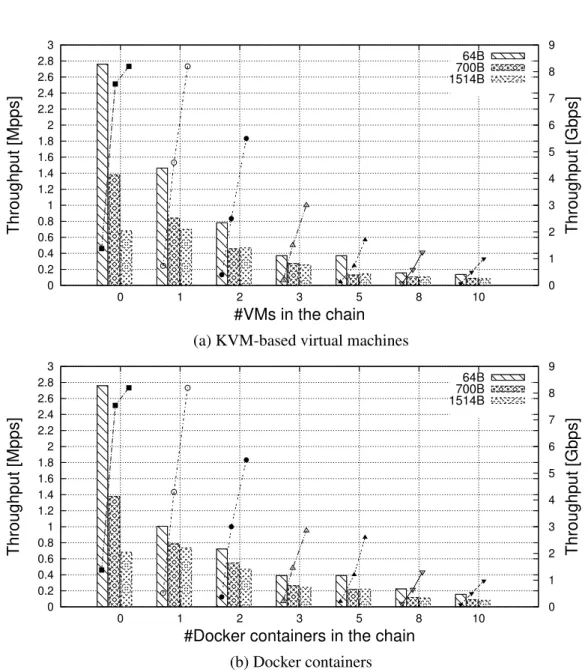
2.5 Throughput of a single chain (of growing length) with VNFs de-ployed. . . 14
2.6 Throughput with several chains implemented with VMs and OvS. . 16
2.7 Throughput with VMs chained through OvS with DPDK. . . 17
2.8 Latency introduced by service chains implemented through different technologies. . . 18
3.1 Deployment of the algorithm within a middlebox. . . 23
3.2 Run-time behavior and indexes of the algorithm. . . 31
3.3 Binding primary buffer - auxiliary buffer. . . 33
3.4 Throughput of a single function chain. . . 39
3.5 Latency introduced by the function chain with a growing number of cascading Workers. . . 41
3.6 Internal throughput of the function chain, with real Workers and a 1M packets in memory. . . 43
3.7 Throughput of a single function chain when other data exchange
algorithms are used. . . 44
3.8 Results with a growing number of function chains running in parallel, each one spotting two Workers in cascade. . . 47
3.9 Results with a function chain of growing length, with the Master accessing to the network. . . 48
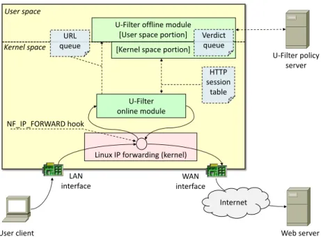
4.1 U-Filter workflow. . . 52
4.2 U-Filter architecture. . . 53
4.3 HTTP session table, shared between online and offline modules. . . 55
4.4 URL queue, shared between the online module and the offline mod-ule user space process. . . 56
4.5 Verdict queue, shared between the offline module kernel thread and user space process. . . 56
4.6 Summarized workflow of the online module. . . 59
4.7 Offline module user space process. . . 60
4.8 Summarized workflow of the offline module kernel thread. . . 61
4.9 Testbed setup. . . 64
4.10 Progress of a TCP session. . . 66
4.11 Waiting time for a single HTTP resource - Cumulative distribution function. . . 69
4.12 Resource waiting time considering the 90thpercentile of the process-ing time and RTT with the policy server in a data center. . . 70
4.13 Complete page loading time cumulative distribution. . . 71
4.14 Complete page loading time considering the 90thpercentile policy server processing time with the policy server in a data center. . . 72
4.15 Application-level throughput when downloading files of different sizes. . . 73
4.17 U-Filter load. . . 75
5.1 Detailed architecture of COMPOSER. . . 85
5.2 Excerpt of Network Functions - Forwarding Graph (NF-FG). . . 87
5.3 Examples of SAPs in the NF-FG. . . 88
5.4 UsingGRESAPs to set up traffic steering between subgraphs. . . . 89
5.5 c-orch new NF-FG deployment message sequence diagram. . . 92
5.6 Example of transformation of NF-FGflowrulesin traffic steering rules. . . 97
5.7 Service deployment time: (a)used service graph; (b)results with COMPOSER;(c)results with OpenStack. . . 103
5.8 Testbed to validate the COMPOSER when running NNFs. . . 105
6.1 Service graph deployment in a multi-domain environment. . . 112
6.2 Domain abstraction based onfunctionalandconnectioncapabilities. 114 6.3 Service chain deployment involving two domains directly connected. 117 6.4 Service chain deployment involving three domains: domain-A and domain-C execute NFs, whiledomain-B just implements network connections. . . 120
6.5 Inter-domain traffic steering based on information associated with SAPs. . . 121
6.6 Validation scenario: (a) service chain split across three domains; (b) service chain deployed in two domains. . . 124
2.1 Bare-metal throughput of the applications used in our measurements. 13 4.1 Inferred RTT values with the policy server in different locations
(RT TP). . . 68
4.2 Inferred policy server latency values (TprocP ). . . 68
5.1 Management interface. . . 93
5.2 Control interface. . . 93
5.3 LSIs involved in implementing flow rules with specific match/action. 94 5.4 Compute interface. . . 97
5.5 Machines used in the validation. . . 100
5.6 Resources consumed by COMPOSER and OpenStack. . . 102
Introduction
Network Function Virtualization (NFV) is a recent network paradigm with the goal of transforming in software images those network functions that for decades have been implemented in proprietary hardware and/or dedicated appliances, such as NAT, firewall, and so on. These software implementations of network functions, called Virtual Network Functions (VNFs) in the NFV terminology, can be executed on high-volume standard servers, such as Intel-based blades. Moreover, many VNFs can be consolidated together on the same server, with a consequent reduction of both fixed (CAPEX) and operational (OPEX) costs for network operators.
The European Telecommunication Standard Institute (ETSI) started the Industry Specification Group for NFV [1], with the aim of standardizing the main components of the NFV architecture. Instead, the IETF Service Function Chain [2] working group takes into account the creation of paths among VNFs; in particular, they introduce the concept of Service Function Chain (SFC), defined as the sequence of VNFs processing the same traffic in order to implement a specific service (e.g., a comprehensive security suite). Hence, a packet entering in a server executing VNFs may need to be processed in several VNFs (of the same chain) before leaving such a server. Moreover, several chains are allowed on a single server, which can process different packet flows in parallel.
Within this context, the Software Defined Networking (SDN) technology is used mainly to create logical connections between multiple VNFs. The main idea of SDN is to centralize all the control logic of the network on a dedicated server (a.k.a. SDN controller), while the devices are in charge of performing only the packet forwarding
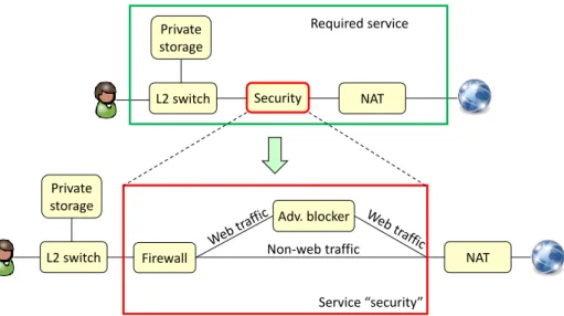
Firewall Adv. blocker Non-web traffic Private storage Security NAT L2 switch Required service Service “security” Private storage L2 switch NAT
Fig. 1.1 Service graph expansion.
based on the rules configured by this controller. An example and enabler of the SDN concepts is the OpenFlow protocol [3]; in such a scenario, an OpenFlow switch can be used to distinguish the various types of traffic and steer them to the correct network function.
Using these concepts we can define a virtualized network service graph that is a set of functions suitably interconnected to implement a specific service, such as, for example a comprehensive security solution. As illustrated in Figure 1.1, links between functions can be potentially marked with the traffic that has to cross such connections, thus enabling the differentiation of various types of traffic. In addition, according to the recursive functional blocks concept proposed by ETSI [4], each function may, in turn, be defined as a service graph. As an example, the NF security block (e.g., a service) in Figure 1.1 is in fact a service graph comprising a firewall and an advertisement blocker (adv-blocker). Therefore, a service graph covers aspects of both the ETSI network service and the ETSI NF forwarding graph.
The idea of deploying a virtualized network service introduces some issues. Network applications are mostly I/O-intensive, differently from traditional cloud ones which are usually CPU-bounded, hence the the virtualised technologies need to be improved to maximize the network performance. Virtualization techniques may not be appropriate to execute services on edge nodes (e.g., home gateways) that feature limited hardware (e.g., CPU, memory) capabilities; moreover, a complex service may require the cooperation of the edge device and the cloud, with components
Private storage
Adv-blocker
Firewall Service graph
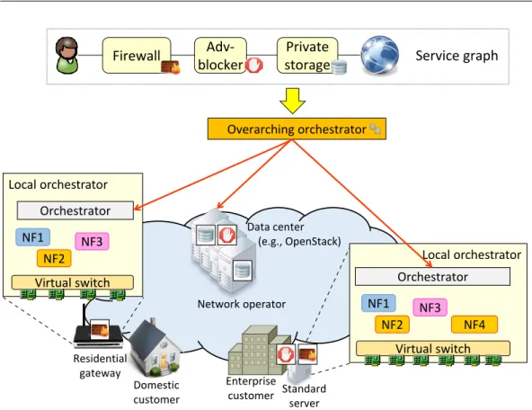
Overarching orchestrator Local orchestrator Virtual switch NF1 NF2 Orchestrator NF3 NF4 Residential gateway Network operator Local orchestrator Virtual switch NF1 NF2 Orchestrator NF3 Enterprise customer Data center (e.g., OpenStack) Domestic
customer Standardserver
Fig. 1.2 Graph deploying on a NFV distributed architecture.
instantiated on both sides. This may require an overarching layer of orchestration that decides the service location; in this distributed scenario, the service has to be split in several sub-components, instantiated on different nodes, which need to be properly interconnected through logical links. Figure 1.2 provides an high-level view of the overall operations.
The aim of the dissertation is to address the problems that can be encountered on an orchestration layer to optimize the path that the user traffic has to flow on the required network functions. The technologies supported by the different nodes introduces penalties in terms of performance and the orchestration layer has to choose the right implementation. The thesis also addresses how to leverage on resource constrained devices as NFV node that can run types of NF and can be used during the placement decisions of the orhchestrator.
This dissertation addressed the described issues starting from Chapter 2, which provides with an analysis of exiting virtualization technologies for an NFV platform in term of performance with respect to network traffic; subsequently Chapter 3 describes an efficient algorithm for the data forwarding inside a single server.
Chapter 4 describes a native network application that can be deployed on a resource constrained device and leverages the presence of a distributed infrastructure. A lightweight NFV node, on-purpose designed to operate on resource constrained devices exploiting their native capabilities (software that runs on the bare hardware) as VNF, is presented in Chapter 5. However, more complex services can exceed the capabilities of a single node and require a distributed scenario, as VNFs are deployed over the whole network infrastructure, even on different technological domains; to tackle this challenge, Chapter 6 presents the concept of a multi domain orchestration for the deployment of network service graphs. Finally, Chapter 7 concludes the thesis.
Assessing the performance of
virtualization technologies for NFV
Part of the work described in this chapter has been previously published in [5].
2.1
Overview
NFV is heavily based on cloud computing technologies; in fact, VNFs are typically executed inside Virtual Machines (VMs) or in more lightweight virtualized environ-ments (e.g., Linux containers), while the paths among VNFs deployed on a server are created through virtual switches (vSwitches). While these technologies have been well tested/evaluated for the cloud computing environment, such a study is still missing in case of NFV services. The rationale is that cloud computing and NFV services differ both in the amount and in the type of traffic that has to be handled by applications and vSwitches, due to the following reasons. First, traditional vir-tualization has to deal most with compute-bounded tasks, while network I/O is the dominant factor in NFV (the main operation of a VNF is in fact to process passing traffic). Second, a packet may need to be handled by several VNFs before leaving the server; this adds further load to the vSwitch, which has to process the same packet multiple times. Finally, common techniques to improve network I/O such as Generic Receive Offload (GRO) and TCP Segmentation Offload (TSO) may not be appropriate for NFV, since some VNFs (e.g., L2 bridge, NAT) need to work on each single Ethernet frame, and not on TCP/UDP segments.
This chapter describes a preliminary benchmarking of VNFs chains deployed on a single server and based on the most common virtualization components. Particularly, KVM [6] and Docker [7] as execution environments, and Open vSwitch (OvS) [8] without and with DPDK enabled as vSwitches to steer the traffic among them in order to implement the chain(s).
This chapter is organized as follows. Section 2.2 provides an overview of the related works, while Section 2.3 details the technologies considered in our benchmarking. Tests are detailed in Section 2.4, while Section 2.5 concludes the chapter.
2.2
Related work
Several works available in literature evaluate the performance of virtualization components, both in the computing virtualization side (i.e., VMs, containers) and in the network virtualization side (i.e., vSwitches).
From the virtual networking side, [9] and [10] provide a deep evaluation of the behavior of OvS, analyzing how several factors, such as CPU frequency, packets size, number of rules and more, influence the performance of the vSwitch itself. Moreover, [9] measures the throughput obtained when OvS is exploited to intercon-nect a single VM both with the physical network and with a second VM executed on the same server. However, both the papers do not evaluate OvS when used to cascade several VNFs, as well as they do not consider Docker containers and OvS with DPDK enabled.
In [11], Casoni et al. measure the performance of chains of Linux containers (LXC) [12] interconnected through different technologies: the VALE vSwitch [13], the Linux bridge and the Virtual Ethernet interfaces (veth), missing some other widespread technologies such as OvS.
From the computing virtualization side, [14] studies the overhead introduced by the KVM hypervisor [6] when accessing to the disk and to the network. However, it does not evaluate such overhead in a VNF scenario, in which a packet has to potentially traverse several VNFs before leaving a server. This scenario is again not considered in [15], although it provides a comparison between LXC containers and KVM-based VMs. Xavier et al. [16] evaluates networking performance of
several virtualization technologies: the Xen hypervisor [17], LXC, OpenVZ [18] and Linux-VServer [19]. However, the tests provided in the paper focus on High Performance Computing workloads, which can be consistently different from those experienced on a server running chains of VNFs.
2.3
Background
This section provides an initial evaluation of the overhead introduced by VNF chains deployed on a single server. Different technologies are considered for what regards both the virtual environment running the VNFs, and the vSwitch interconnecting such functions together and with the physical network, in order to identify their performance and compare such technologies among each other.
VMs are the main virtualization technology used to execute VNFs, since they provide strong isolation among VNFs themselves. However, lightweight containers are gaining momentum, since they still provide a form of isolation while having lower resources demand. As environment to execute VNFs, the section considers KVM-based VMs [6] and Docker [7] containers.
Interconnections among VNFs are implemented through a vSwitch, exploiting its capabilities to perform traffic steering based on multiple criteria such as the port ID and L2-L7 protocol fields. Although several vSwitches are available, the analysis is focused on the most widespread ones, namely Open vSwitch (OvS) [8] and OvS based on the Intel Data Plane Development Kit (DPDK) technology [20].
The remainder of this section provides an overview of the OvS I/O model, as well as it gives some insights on KVM-based VMs and Docker containers, mainly focusing on the way in which they connect to the vSwitch.
2.3.1
KVM-based virtual machines and networking
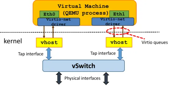
Figure 2.1 provides an overview of the components involved in the network I/O of VMs running in the KVM hypervisor.
Before detailing how VMs send/receive network packets, it is worth mentioning that KVM is just a kernel module that transforms the Linux kernel into an hypervisor, i.e., it provides to the Linux kernel the capability of running VMs. A VM is then
Fig. 2.1 Networking of a KVM-based virtual machine.
executed within QEMU, which is a Linux user-space process that exploits KVM to execute VMs. For instance, the VM memory is part of the memory assigned to the QEMU process, while each virtual CPU (vCPU) assigned to the VM corresponds to a different QEMU thread in the hypervisor.
As shown in Figure 2.1, the guest operating system (i.e., the operating system executed in the VM) accesses to the virtual NICs (vNICs) through thevirtio-net
driver [21], which is a driver optimized for the virtualization context. Each vNIC is associated with twovirtio queues(used to transmit and receive packets) and a process running in the Linux kernel, namely thevhostmodule in the picture. As shown,vhostis connected to thevirtio queueson one side, and to a tap
interface on the other side, which is in turn attached to a vSwitch. vhostworks in interrupt mode; particularly, it waits for notifications from both the VM and thetap
and then, when such an interrupt arrives, it forwards packets from one side to the other.
As a final remark, the transmission of a batch of packets from a VM causes aVM exit; this means that the CPU stops to execute the guest (i.e., the vCPU thread), and runs a piece of code in the hypervisor, which performs the I/O operation on behalf of the guest. The same happens when an interrupt has to be “injected” in the VM, e.g., becausevhosthas to inform the guest that there are packets to be received. These
Container
Container
Container network namespace Veth interface Host network namespace Container network namespacevSwitch
Fig. 2.2 Networking of a Docker container.
VM exits(and the subsequentVM entries) are one of the main causes of overhead in
network I/O of VMs.
2.3.2
Docker containers and networking
Docker containers are a lightweight virtualization mechanism that, unlike VMs, do not run a complete operating system: all the containers share the host’s kernel1. Containers represent a way to limit the resources visible by a running userland process; hence, if no process is running in the container, such a container is not associated with any thread in the host. Such this limitation of resources (e.g., CPU, memory) is achieved through the cgroups feature of the Linux kernel, while isolation is provided through the Linux namespaces, which give to processes running in the container a limited view of the process trees, networking, file system and more.
As shown in Figure 2.2, each container corresponds to a different network namespace; this means that it is only aware of those interfaces inserted into its own namespace, as well as it has a private network stack. According to the picture, packets can traverse the namespace boundary by means ofvethpairs, which are in fact a pair of interfaces connected through a pipe: packets inserted in one end are received on the other end. Hence, by putting the two ends of thevethin different namespaces, it is possible to move packets from one network namespace to another. According to the picture, a vSwitch connects all the vethinterfaces in the host namespace among each other and with the physical network.
1In other words, on the physical machine there is a single kernel, with a single scheduler, a single
ovs-vswitchd
ovs_mod.ko
User-space Kernel-space Slow path Fast pathFig. 2.3 Open vSwitch data-plane architecture.
2.3.3
Open vSwitch I/O model
OvS is a widespread vSwitch, whose data plane architecture is depicted in Figure 2.3; as shown, it consists of a user-space daemon and a kernel-space module, respectively referred asovs-vswitchdandovs-mod.koin the picture.
The kernel module implements the fast path; it acts in fact as a cache for the user-space component, and includes all the last matched rules for increasing forwarding efficiency. In particular, when a packet enters into the vSwitch, it is first processed in the kernel module, which looks for a cached rule matching such a packet. In case of positive result, the corresponding action is executed, otherwise the packet is provided to the user-space.
The user-space daemon (that implements the slow path) contains in fact the full forwarding table of the vSwitch. By default, it implements the traditional MAC learning algorithm, although it can also be “programmed” by an external controller through the Openflow protocol2. Then, after that the first packet of a flow has been handled in user-space, the corresponding rule is offloaded to the kernel module, which will be able to handle all the subsequent packets of the same flow, thus significantly increasing the performance.
Interesting, there are no threads associated with theovs-mod.kokernel mod-ule; the in-kernel code of OvS consists in fact of a callback invoked by the software interrupt raised when a packet is available on a network interface. For instance, the OvS code (in the hypervisor) is executed in the context of theksoftirq kernel thread in case of packets coming from the physical NIC, while it is executed in the context of thevhostassociated with the “sender” vNIC in case of packets coming
2The capability to program the switching table of OvS from an external entity is exploited in NFV
from the VM (Figure 2.1). In case of packets coming from Docker (Figure 2.2), OvS runs in the context of the process executed in the container. This is possible because a single kernel exists, which is shared among the host and the containers.
2.3.4
OvS with DPDK I/O model
DPDK is a framework proposed by Intel that offers efficient implementations for a wide set of common functions, such as NIC packet input/output, memory allocation and queuing.
Unlike the standard OvS, enabling DPDK simply consists of a user-space process (with a variable number of threads) that continuously iterates over the physical NICs and the virtio queues. The vhost module shown in Figure 2.1 is in fact integrated in the vSwitch, so that thetapinterface, which introduces overhead in the data path of packets to/from VMs, is removed. Furthermore, thanks to DPDK:(i)
the vSwitch accesses to the physical NICs without the intervention of the operating system;(ii)packet transfer between the physical NICs and the vSwitch is done with zero-copy.
As a final remark, OvS with DPDK can also exchange packets with the VMs through shared memory: this solution removes the vhost at all, and does not require thevirtio-netdriver in the VMs. Although this configuration allows the vSwitch to move packets in a zero-copy fashion among VMs, we decided of not using it in our preliminary benchmarking of service chains. In fact, due to a design choice of DPDK, the same memory would be shared among all the VMs deployed, thus weakening the isolation among VMs themselves.
2.4
Performance characterization
This sections details our benchmarking of VNFs chains implemented on a single server. As already mentioned, we carried out several tests using different technologies for what regards both the virtualization environment used to run VNFs (KVM and Docker), and the vSwitch that properly steers the traffic among them in order to create the chain(s) (OvS and OvS with DPDK enabled).
Sender
Server with VNFs
Receiver
VNF VNF
…
VNFvSwitch
Fig. 2.4 Physical set up used for the tests.
Particularly, the tests focus on measuring the throughput and latency obtained when packets (of different size) flow through a server hosting one or more chains of different length. Each measurement lasted 100 seconds and was repeated 10 times; results are then averaged and reported in the graphs shown in the following of this section. Some graphs are provided with a bars view and a points-based representation of the maximum throughput. The former representation is referred to the leftyaxis, which provides the throughput in Mpps, while the latter is referred to the rightyaxis, where the throughput is measured in Gbps.
2.4.1
Hardware and software setup
As shown in Figure 2.4, the test environment includes a server that runs a vSwitch and a variable number of VNFs; the server is connected to a sender and to a receiver ma-chine through two point-to-point 10Gbps Ethernet links. All the physical mama-chines are equipped with an Intel Core i7-4770 @3.40GHz (4 physical cores plus hyper-threading), 32GB of memory, and run Fedora 20 with kernel 3.18.7-100.fc20.x86_64. The physical network interfaces are instead Intel X540-AT2.
As already mentioned, VNFs are executed either in KVM-based VMs3, or in Docker containers. According to Figure 2.4, each VNF is equipped with two vNICs connected to the vSwitch. In order to steer the traffic among VNFs, the vSwitch is configured with Openflow rules matching the input port of packets, while the action is always the forwarding of packets through a specific port. In case of multiple service chains deployed on the server, the traffic entering from the physical port is split so that some packets enter in one chain, other packets in another chain and so on.
3In this case, each VM is associated with a single vCPU, i.e., the whole VM corresponds to a single
thread in the hypervisor. Moreover, the guest operating is Ubuntu 14.04 with kernel 3.13.0-49-generic, 64 bit.
Table 2.1 Bare-metal throughput of the applications used in our measurements.
Linux bridge libpcap-based bridge DPDK-L2fw
64B
2.39 (1,14) 1.29 (0.66) 8.78 (4.39)
[Mpps (Gbps)]
Traffic splitting is based on the source MAC address of packets, which are properly generated so that they are equally distributed among all the available chains.
Particularly, our VNFs simply receive packets from one interface and forward them on the other; such applications, in a non-virtualized environment (i.e., when used to directly connect two physical interfaces), provide the throughput shown in Table 2.1.
The throughput is measured using unidirectional traffic flowing from the sender to the receiver machine, respectively running a packet generator and a packet receiver based on thepfring/dna[22] library, which allows to transmit/receive packets at 10Gbps.
2.4.2
OvS-based chains: virtual machines vs Docker containers
This section evaluates the throughput achieved when a single chain of VNFs is deployed on a server running OvS as vSwitch4. Measurements have been repeated with VMs and Docker containers, chains of growing length and packets of different size; results are reported in Figure 2.5. Those graphs have been obtained by executing the Linux bridge within VMs, while each container runs a simple user-space bridge based onlibpcap[23]. In fact, with the Linux bridge inside containers, we got an unacceptable throughput of 3Mbps with 8 chained VNFs.This poor result is a consequence of two factors:(i)the Linux bridge data plane is in fact a kernel-level callback executed in the context of the thread that provides packets to the vSwitch (similarly to OvS);(ii)all Docker containers share the kernel with the host (as detailed in Section 2.3.2). As a consequence, theksoftirqkernel thread that processes the packet received from the physical NIC is also in charge of executing(i)the OvS code that forwards the packet in the first container;(ii)the data plane part of the Linux bridge launched in the first container (but running, in fact, in
4Note that, due to the small number of rules inserted in the vSwitch, the packet processing is
0 0.2 0.4 0.6 0.8 1 1.2 1.4 1.6 1.8 2 2.2 2.4 2.6 2.8 3 0 1 2 3 5 8 10 0 1 2 3 4 5 6 7 8 9 Throughput [Mpps] Throughput [Gbps] #VMs in the chain 64B 700B 1514B
(a) KVM-based virtual machines
0 0.2 0.4 0.6 0.8 1 1.2 1.4 1.6 1.8 2 2.2 2.4 2.6 2.8 3 0 1 2 3 5 8 10 0 1 2 3 4 5 6 7 8 9 Throughput [Mpps] Throughput [Gbps]
#Docker containers in the chain
64B 700B 1514B
(b) Docker containers
the host kernel);(iii)again OvS, and so on, until the packet leaves the server through the physical NIC. In other words a single kernel thread executes all the operations associated with the packet, resulting in no parallelization at all and hence in really poor performance, especially in case of long chains.
Instead, in case of VMs, the vCPU thread (Section 2.3.1) executes the guest kernel and hence the Linux bridge, whilevhostexecutes the OvS code, thus providing high parallelization in packets processing and then acceptable performance. In case of Docker, such a parallelization can be achieved by running a VNF that is actually a process (e.g, our simplelibpcap-based bridge). This way, the OvS code between VNFs is executed in the context of this process, and theksoftirqis just involved at the beginning of the service chain.
A comparison between Figure 2.5a and Figure 2.5b shows that chains imple-mented with the two virtualization technologies (when executing the proper applica-tion) present different throughput only when there is a single VNF per chain (and 64B packets), while they are almost equivalent in the other cases. However, according to Table 2.1, the Linux bridge provides nearly twice the throughput of thelibpcap -based bridge, when executed in a non-virtualized environment. The fact that we got almost the same throughput by running these two applications respectively in VMs and containers, shows how the overhead introduced by full virtualization is higher than the overhead due to lightweight virtualization mechanisms.
Figure 2.5 also shows that the throughput is inversely proportional to the number of chained functions, regardless of the virtualization environment. In fact, more VNFs executed on the same server results in more contention on the CPU resource, as well as on the cache(s) and the Translation Lookaside Buffer (TLB). Furthermore, with longer chains, the probability that a packet is processed on different physical cores is higher, with a consequent increasing in the number of experienced cache misses. Moreover, although OvS is executed on several threads, there is just one instance of the forwarding table, which requires synchronization for example to increment the counters associated with the matched rules.
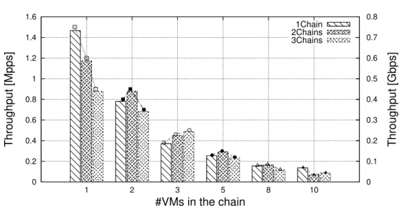
Figure 2.6 reports instead the throughput obtained when 64B packets are equally distributed among multiple chains of VMs. As evident, more chains result in lower throughput measured on the receiver machine, for the same reasons stated above in case of a single chains of different lengths (i.e., more CPU contention, more cache misses, etc.). Similar results have been achieved with containers.
0 0.2 0.4 0.6 0.8 1 1.2 1.4 1.6 1 2 3 5 8 10 0 0.1 0.2 0.3 0.4 0.5 0.6 0.7 0.8 Throughput [Mpps] Throughput [Gbps] #VMs in the chain 1Chain 2Chains 3Chains
Fig. 2.6 Throughput with several chains implemented with VMs and OvS.
We can then conclude that Docker containers are well suited to run VNFs only in case of applications associated with a specific thread/process. In this case, they provide almost the same performance of KVM-based VMs, with the advantage of requiring less resources (e.g., memory), but with the drawback of providing less isolation.
2.4.3
KVM-based virtual machines: OvS with DPDK enabled
and not
This section evaluates the performance of a chain of VNFs interconnected through OvS with DPDK, and compares such results with those achieved in case of OvS without DPDK. Particularly, in order to compare the two switching technologies, we consider VNFs executed in KVM-based VMs. Before analyzing the results, it is worth remembering that , unlike the standard OvS, DPDK is entirely executed in user-space and works in polling, i.e., it continuously iterates over the available NICs. Moreover, thevhostmodule (Figure 2.1) is replaced with a software layer integrated in DPDK, so that VMs directly communicate with the vSwitch.
As a first test, we consider again the Linux bridge as VNFs, obtaining a through-put that is just slightly better than those achieved with OvS and depicted in Fig-ure 2.5a; e.g., 1.66Mpps (0.85Gbps) with 64B packets traversing a singe VNF. In
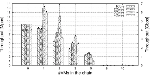
0 1 2 3 4 5 6 7 8 9 10 11 12 13 14 0 1 2 3 5 8 10 0 1 2 3 4 5 6 7 Throughput [Mpps] Throughput [Gbps] #VMs in the chain 1Core 2Cores 3Cores 4Cores
Fig. 2.7 Throughput with VMs chained through OvS with DPDK.
fact, although DPDK provides several enhancements with respect to OvS standard, such improvements are mitigated by the high overhead introduced by VMs.
Then, we installed DPDK in VMs as well, in order to execute DPDK-based VNFs and exploits the DPDK acceleration both in the guest and in the hypervisor. In particular, results shown in Figure 2.7 are gathered using the L2-forwarded application provided with the DPDK library (and 64B packets). The test has then been repeated by changing the number of polling threads (and hence CPU cores) associated with the vSwitch, in order to evaluate its effect on the performance of the chain. Note that, since the L2-forwarder , as any other DPDK-based process, works in polling, during this test we always have to dedicate a CPU core to the vCPU thread associated with each VM.
According to the picture, assigning more cores to the vSwitch results in better performance in case the number of cores required by the whole chain (VMs + vSwitch) does not exceed the number of cores of the server. When this happens, performance degrades until becoming unsustainable with 8 chained VMs. In fact, at this point some cores are shared among many polling threads and, for instance, it may happen that the operating system assigns the CPU to a VNF with no traffic to be processed, penalizing others that would actually have work to do.
For the sake of clarity, Figure 2.7 only reports the throughput obtained with 64B packets. However, our measurements also reveal that a chain implemented with OvS and the DPDK L2-forwarder within VMs, provides a throughput of 10Gbps in case
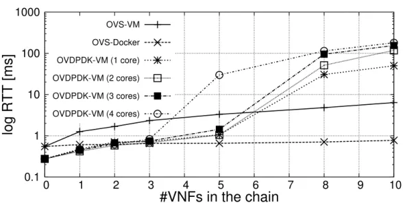
0.1 1 10 100 1000 0 1 2 3 4 5 6 7 8 9 10
log RTT [ms]
#VNFs in the chain
OVS-VM OVS-Docker OVDPDK-VM (1 core) OVDPDK-VM (2 cores) OVDPDK-VM (3 cores) OVDPDK-VM (4 cores)Fig. 2.8 Latency introduced by service chains implemented through different technologies.
of 700B and 1514B packets. Of course, such results are obtained only in case the chain does not require more cores than those available on the server.
A comparison between Figure 2.7 and Figure 2.5a reveals how chains imple-mented through DPDK-based components (i.e., OvS and VMs running DPDK applications) outperform chains not based on the DPDK library. In fact, DPDK-based modules works in polling and optimize the data transfer among each others, exploiting zero-copy as much as possible. However, as already stated above, the polling working model has the drawback of providing unacceptable throughput when the cores required exceed the number of cores available on the server.
2.4.4
Latency
In networking, the latency introduced by the system is as important as the throughput achieved. Hence, this section reports the latency measured with a single chain implemented with the technologies discussed above. In particular, for each scenario, we executed 100pingbetween the sender and the receiver machines; results have been averaged and reported in Figure 2.8.
As expected, DPDK-based chains (OvS + DPDK-L2forwarder in VMs) provide better results, provided that the number of cores required does not exceed the number of cores of the physical machine on which such a chain is deployed. At this point,
similarly to what already discussed in case of throughput, latency becomes definitely unacceptable.
Figure 2.8 also shows how Docker containers running a user-space process (i.e., the simplelibpcap-based bridge) introduce smaller latency than VMs. This difference in performance is again a consequence of the higher overhead introduced by full virtualization with respect to lightweight containers.
2.5
Conclusion
This chapter provides a performance analysis of service chains implemented through different virtualization technologies, selected among those representing the state of the art in the NFV domain.
From the several tests carried out, we can draw the following conclusions. First, Docker containers provide acceptable results only in case of VNFs associated with a specific process, while they are definitively unsuitable for VNFs implemented as callbacks to be executed in the kernel. However, due to the low overhead introduced by lightweight virtualization, a user-space program in Docker provides better latency and almost the same throughput of callback-based VNFs (e.g., Linux bridge) run within VMs kernel. Second, OvS with DPDK enabled (when used with VMs running DPDK-based applications) provides much better performance than standard OvS. For instance, this is due to the exploitation of zero-copy when transferring packets to/from physical NICs, and to the polling model implemented by DPDK-based processes. However, the polling model requires at least a dedicated core per VM, hence limiting the usage of DPDK in servers with a reduced number of VNFs.
Given that a single-technology-fits-all recipe is not available in this domain, future NFV services need to heavily rely on a smart orchestration system, which should be able to select the implementation to use for the different NFs required to get advantages from them, depending on the specific service required.
Designing an efficient data exchange
algorithm
Part of the work described in this chapter has been previously published in [24].
3.1
Overview
As analyzed on Chapter 2 when VNFs are deployed on a single server, an incoming packet could possibly traverse an arbitrary number of VNFs before leaving the middlebox and this requires each server to include a module (usually referred as
virtual switchorvSwitch) that classifies each packet to determine the path that has to traversed. All this operations cause a drop of performance as shown in Chapter 2.
This chapter proposes and evaluates an efficient algorithm to improve the for-warding of network packets between VNFs consolidated on the same server and the vSwitch, which is based on circular lock-free First-In-First-Out (FIFO) buffers managed by ad-hoc algorithms.
Existing solutions adopted to move packets between VNFs and the vSwitch are usually based on the producer-consumer paradigm. However, since in NFV it is likely that a packet goes from the vSwitch to the VNF and then back to the vSwitch, those approaches require the VNF to copy (almost) each packet from a first receiving queue into a second queue used for sending it back. Instead, the model shown on
this chapter has the advantage of allowing VNFs to return back packets without any (expensive) packet copy, with consequent performance improvements.
Particularly, the proposed mechanism is designed to: (i)guaranteetraffic isolation
between functions, so that a function can only access the portion of traffic that is expected to flow through it, to limit the potential hazards that a malicious applications could cause providing an effective support to multitenancy;(ii) provide excellent
scalabilityby allowing to consolidate a huge number of VNFs on the same server;(iii)
achieve highperformancein terms of data movement speed among different VNFs. Scalability and performance are obtained also by taking care of implementation details such as exploiting cache locality as much as possible and limiting the number of context switches.
The Chapter is organized as follows. Section 3.2 describes related other solutions able to exchange data among different software components. Section 3.3 details the main operations of the designed algorithm and how it communicates with the different modules. Section 3.4 shows some implementation choices used to increase the performance of the algorithm. Section 3.5 contains a validation of the algorithm both in ideal conditions and in real scenarios. Finally, Section 3.6 concludes the chapter.
3.2
Related work
The efficiency of FIFO queues implemented aslock-freehas been already analyzed in the past. For instance, [25] and [26] propose different type of lock-free algorithms for FIFO queues that are managed as non-circular linked-lists. Other proposals can be found in [27] and [28], that also require to create a pool of pre-allocated memory slots. However, the related solutions are usually based on uni-directional flows of data according to theproducer-consumerparadigm, which is not the best solution for managing the bi-directional data flows that is strongly present on the case of virtualized environments. In fact, in these environments, a packet typically goes from the virtual switch to the VNF and then goes back. Using classical uni-directional producer-consumer solutions requires the VNF to remove data just received from a first queue and to write them into a second queue used for sending the data back.
A similar solution can be found in the Intel DPDK library [20] and in [29], which contains algorithms designed to operate in contexts where many processes can concurrently do operations on ashared buffer. However, those proposals can-not guarantee isolation between VNFs because they use a unique shared buffer. Similar considerations can be made for ClickOS [30, 31] (based on the VALE vir-tual switch [13]) and NetVM [32], which instead targets network function chains. ClickOS uses two unidirectional queues with the necessity to copy packets once; NetVM uses two unidirectional queues between “untrusted” functions, while switch-ing to a unique shared buffer (handled in zero-copy) among “trusted” functions, hence compromising traffic isolation requirement. MCRingBuffer [33], instead, de-fines an algorithm to exchange data between a producer and a consumer executing on different CPU cores, which is particularly interesting for its efficient implementation of memory access patterns; in fact, part of those techniques were reused on the implementation (Section 3.4).
3.3
The data exchange algorithm
The implementation of an efficient virtual functions chains within a single middlebox requires a fast and efficient mechanism to transfer data between the vSwitch and the VNFs. This requirements is translated into the necessity of a dedicated data dispatching algorithm, which among the ones having the greatest impact on the overall system performance. This section provides a description of the designed algorithm.
In the context of the algorithm, theMasteris the module that acts as the vSwitch, while theWorkersare the VNFs. Moreover, atokenis a generic data unit exchanged between the Master and the Workers. The token can be a packet for the NFV use case, but the proposed algorithm can be actually used to exchange any kind of data, according to the specific use case implemented.
3.3.1
Algorithm overview
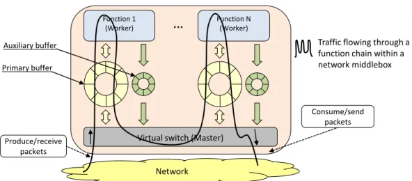
As shown in Figure 3.1, the proposed data exchange algorithm is composed of a set of lock-free ring buffers; in particular, the Master shares two different buffers with
Function 1 (Worker)
…
Function N (Worker) Consume/send packets Produce/receive packetsVirtual switch (Master)
Network
Traffic flowing through a function chain within a network middlebox
Primary buffer Auxiliary buffer
Fig. 3.1 Deployment of the algorithm within a middlebox.
each Worker, which are managed through different (but not independent) parts of the same exchange algorithm.
The intuition behind the algorithm, which is based on the NFV use case, is the following. VNFs are pieces of software operating on the data plane of the network, which mainly process pass-through packets. In fact, VNFs receive packets from the vSwitch and, in the vast majority of cases, forward them back to the vSwitch itself with minimal (or no) changes (functions as NAT or IDS), allowing packets to continue their journey towards the final destination. To efficiently support pass-through data, the model defines theprimary buffershown in Figure 3.1, which has the peculiarity of allowing tokens to be moved both from the Master to the Worker, and then back from the Worker to Master, without requiring any (expensive) copy of data in the Worker itself.
Avoiding to copy each packet in each traversed VNF can save in fact many CPU cycles and consequently improve the performance of virtualized functions chains. Notably, in addition to VNFs operating on pass-through data, the primary buffer also supports functions that need to drop packets (e.g., firewall), which should then not be sent back to the vSwitch after their processing in the VNF.
Some network functions may need to generate new packets as a consequence of a previously received packet. For example, a bridging module may need to duplicate a broadcast packet several times (e.g., once for each interface of the middlebox) and then provide all these copies to the next function in the chain. Similarly, another function may modify a packet (e.g., by adding a new header) so that it exceeds the
MTU of the network; this packet must then be fragmented, and all the fragments must be sent out. Since network applications forward most of the traffic without generating new packets, the primary buffer is designed to be as simple as possible for the sake of speed, and then use a new second lock-free ring buffer, i.e., theauxiliary bufferof Figure 3.1, to support Workers that can possibly generate new tokens as a consequence of the data received from the Master. It is worth noting that this second buffer is unidirectional and it is only used by the Worker to provide “new” data to the Master.
Since VNFs may belong to different tenants, a network function must only accesses to the proper portion of network traffic; to guarantee this property the model uses a different pair of buffers per Worker in order to guarantee traffic isolation among them, as this ensures that a Worker can only access packets that are expected to flow through the Worker itself.
Each buffer slot (both primary and auxiliary) includes some flags in addition to the real data, these flags are used to identify the content of the slot itself; more details will be presented in the next sections.
3.3.2
Execution model
The Master operates in polling mode, i.e., it continuously checks for new tokens and inserts them into the primary buffer shared with the target Worker. This operating mode has been chosen because the middlebox (and then the Master itself) is supposed to be traversed by a huge amount of traffic; hence, a blocking model would be too penalizing requiring an interrupt-like mechanism to start the Master when there are new data. This could significantly drop the performance with high packet rates [34]. In fact, interrupt handling is expensive in modern superscalar processors because they have long pipelines and support out of order and speculative execution [35], which tends to increase the penalty paid by an interrupt.
Vice versa, since the traffic entering into a specific Worker is potentially a small portion compared to the one handled by the Master, a blocking model looks more appropriate for this module. This ensures the possibility to share CPU resources more effectively, which is important in multi-tenant systems where potentially a large number of Workers is active. Hence, when a Worker has no more data to
be processed, it suspends itself until the Master wakes it up by means of a shared semaphore.
3.3.3
Basic algorithm: handling pass-through data
The algorithm used to move data from the Master to the Workers (and back) requires the sharing of some variables (underlined in the pseudocode shown in the following), a semaphore, and the primary buffer between the Master and each Worker. In particular, in this section we assume the presence of the Master and asingleWorker, while its extension to several Workers is trivial.
The primary buffer is operated through four indexes. M.prodIndex and
W.prodIndex are shared between the Master and the Worker. The former
in-dex points to the next empty slot in the buffer, ready to be filled by the Master, while the latter points to the next slot in the buffer that the Worker will make available to the Master again after its processing. M.prodIndexis incremented by the Master when it enqueues new tokens, whileW.prodIndexis incremented by the Worker when it makes processed tokens available to the Master again. M.consIndexis a private index of the Master, which points to the next token that the Master itself will remove from the buffer. Finally,W.consIndexis a private index of the Worker, which points to the next token to be processed by the Worker itself. In addition to these indexes, the algorithm exploits the shared variableworkerStatus, which indicates whether the Worker is suspended or it is running.
Algorithm 1 provides the overall behavior of the Master and shows how it cyclically repeats the following three main operations: (i)in lines 14-21 it produces new data (line 19), which corresponds to the reception of packets from the network interface card (NIC) in the NFV use case (with a maximum of N packets per cycle), and immediately provides them to the Worker through the primary buffer (line 20);
(ii)it reads the tokens already processed by the Worker from the primary buffer (line 22), and finally(iii)it wakes up the Worker if there are data waiting for service for a long time in order to avoid starvation (line 23). From lines 14-21, it is evident that the Master produces several tokens consecutively, in order to better exploit cache locality. Furthermore, if the buffer is full (line 15), it stops data production and starts removing the tokens already processed by the Worker from the buffer.
Algorithm 1Executing the Master
1: Proceduremaster.do()
2:
3: {Initialize shared variables}
4: M.prodIndex←0
5: W.prodIndex←0
6: workerStatus←WAIT_FOR_SIGNAL
7:
8: {Initialize private variables of the Master}
9: M.consIndex←0
10: timeStamp←0
11:
12: {Execute the algorithm}
13: whiletruedo
14: fori=0to(i<Nortimeout())do
15: ifM.prodIndex==(M.consIndex−1)then
16: {The buffer is full}
17: break 18: end if 19: data←master.produceData() 20: master.writeDataIntoBuffer(data) 21: end for 22: master.readDataFromBuffer() 23: master.checkForOldData() 24: end while
Algorithm 2 details the mechanism implemented in the Master to send data to the Worker. As shown by line 8, a token is inserted into the slot pointed by the shared indexM.prodIndexas soon as it is produced; however, the Worker is awakened only if at least a given number of tokens (i.e., MASTER_PKT_THRESHOLD) are waiting for service in the primary buffer (lines 10-13). Thanks to this threshold, we avoid to wake up the Worker for each single token that needs to be processed, which results in performance improvement because (i) it reduces the number of context switches and (ii) it increases cache locality, for both data and code. Since a token is inserted into the buffer as soon as it is produced regardless of the fact that the Worker is running or not, and since the Worker will suspend itself only when the buffer is empty (as detailed in Algorithm 5), the Worker is able to process a huge amount of data consecutively, thus improving system performance.
Algorithm 2The Master writing data into the primary buffer
1: Proceduremaster.writeDataIntoBuffer(Data d)
2:
3: ifM.prodIndex==M.consIndexthen
4: {The buffer is empty}
5: timeStamp←now()
6: end if
7:
8: buffer.write(M.prodIndex,d)
9: M.prodIndex++
10: ifbuffer.size()>MASTER_PKT_THRESHOLDand
(workerStatus̸=SIGNALED)then
11: workerStatus←SIGNALED
12: wakeUpWorker()
13: end if
Our algorithm avoids the starvation of tokens sent to a Worker (which may happen especially when the system is in underload conditions) thanks to a timeout event that wakes up the Worker even if the above-mentioned threshold is not reached yet. In particular, the Master acquires and stores the current time whenever it inserts a new token and the buffer is empty (lines 3-6 of Algorithm 2). This way, the Master knows the age of the oldest token and it is able to possibly wake up the Worker also depending on the value of a given time threshold, as shown in Algorithm 3.
The functions described in Algorithm 2 and Algorithm 3 need to know whether the Worker is already running or not in order to avoid useless Worker awakenings. This information is carried by the shared variableworkerStatus, which is set to
Algorithm 3The Master waking up the Worker due to a timeout
1: Proceduremaster.checkForOldData()
2:
3: ifbuffer.size()>0and(workerStatus̸=SIGNALED)and
((now()−timeStamp)>TS_THRESHOLD)then
4: workerStatus←SIGNALED
5: wakeUpWorker()
6: end if
SIGNALEDby the Master just before waking up the Worker (line 11 of Algorithm 2
and line 4 of Algorithm 3), and changed toWAIT_FOR_SIGNAL by the Worker just before suspending itself (line 22 of Algorithm 5). This way, the Master can test this shared variable to have an indication about the Worker status, and then wake it up only when necessary.
Algorithm 4 shows how the Master removes from the primary buffer the data that have already been processed by the Worker. In particular, it consumes all the tokens until the indexM.consIndex does not reach the indexW.prodIndex, incremented by the Worker each time it has handled a batch of tokens, as detailed in Algorithm 5. In this way, also the Master reads several consecutive data from the primary buffer in order to better exploit cache locality.
Algorithm 4The Master reading data from the primary buffer
1: Proceduremaster.readDataFromBuffer()
2:
3: ifbuffer.size()then
4: ifM.consIndex̸=W.prodIndexthen
5: timeStamp←now()
6: whileM.consIndex̸=W.prodIndexdo
7: if notbuffer.dropped(M.consIndex)then
8: master.consumeData(buffer.read(M.consIndex)) 9: end if 10: M.consIndex++ 11: end while 12: end if 13: end if
Notice that Algorithm 4 also considers those tokens provided by the Master to the Worker, and dropped by the Worker itself. In case of dropped data, the Master receives back an empty slot, identified through the flagdropped. The content of a slot is only consumed if this flag is zero, otherwise the Master just increments the
M.consIndexand moves on to the next slot of the buffer, as shown in lines 7-10. This prevents the Master from reading a slot with a meaningless content.
Algorithm 5 details the operations of the Worker. As evident from lines 12-23, whenever a Worker wakes up, it processes all the tokens available in the primary buffer (i.e., all the slots of the buffer with indexes less thanM.prodIndex). Only at this point (line 24), as well as after it has processed a given amount of data (lines 13-16), the Worker updates the shared indexW.prodIndex, so that the Master can consume all the tokens already processed by the Worker itself. This way, the Master will be notified for data availability only when a given amount of tokens are ready to be consumed, with a positive impact on performance. It is worth noting that this batching mechanism is different from the one implemented when the Master sends data to the Worker. In fact, in that case, the Worker is woken up when the amount of data into the buffer is higher than a threshold, although theM.prodIndex, used by the Worker to understand when it has to suspend itself, is incremented each time a new data is inserted. Here, instead, theW.prodIndex(i.e., the index used by the Master to know when the consuming of tokens must be stopped) is not updated each time the Worker processes a data. As a consequence, it is possible that some tokens have already been processed by the Worker, but theW.prodIndexhas still to be updated, and then the Master cannot consume them in the current execution of Algorithm 4. This results in a slightly higher latency for these tokens, but in better performance for the system thanks to this batching processing enabled into the Master. As a final remark, lines 18-20 show that the Worker can drop the token under processing by setting thedroppedflag in the current slot of the primary buffer.
Figure 3.2 depicts the status of the primary buffer1and the indexes used by the algorithm in four different time instants. In Figure 3.2(a) the buffer is empty, and then all the indexes point to the same position. Instead, in Figure 3.2(b) the Master has already inserted some data into the buffer, but the Worker is still waiting since the
MASTER_PKT_THRESHOLDhas not been reached yet. Figure 3.2(c) depicts the
situation in which the Master has woken up the Worker, which has already processed two items. Notice that, since theWORKER_PKT_THRESHOLDhas not been reached yet, the W.prodIndex still points to the oldest token in the buffer. Instead, in Figure 3.2(d) this threshold is passed and the Master has already consumed some data.
1For the sake of clarity, the figure represents the shared buffer as an array instead of a circular
Algorithm 5Executing the Worker
1: Procedureworker.do()
2:
3: {Initialize private variables of the Worker}
4: W.consIndex←0
5: pkts_processed←0
6:
7: {Execute the algorithm}
8: whiletruedo
9: waitForWakeUp()
10: W.consIndex←W.prodIndex
11: pkts_processed←0
12: whileW.consIndex̸=M.prodIndexdo
13: ifpkts_processed==WORKER_PKT_THRESHOLDthen
14: pkts_processed←0 15: W.prodIndex←W.consIndex 16: end if 17: toBeDropped←buffer.process(W.consIndex) 18: iftoBeDroppedthen 19: buffer.setDropped(W.consIndex) 20: end if 21: W.consIndex++ 22: pkts_processed++ 23: end while 24: W.prodIndex←W.consIndex 25: workerStatus←WAIT_FOR_SIGNAL 26: end while
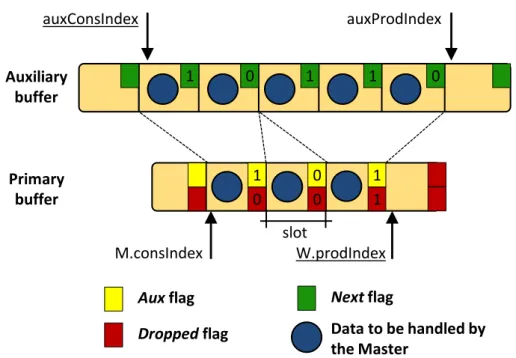
M.prodIndex W.prodIndex W.consIndex M.consIndex M.prodIndex W.prodIndex W.consIndex M.consIndex M.prodIndex W.prodIndex W.consIndex M.consIndex W.consIndex M.consIndex M.prodIndex W.prodIndex MASTER_PKT_THRESHOLD WORKER_PKT_THRESHOLD Token to be handled by the Worker
Token already processed by the Worker a) b) c) d) Token to be removed by the Master
3.3.4
Extended algorithm: handling worker-generated data
The algorithm also supports Workers that may need to generate new token as a consequence of the token just received from the Master; however, this cannot be done with the primary buffer alone, as Workers cannot inject new data into the primary buffer. In fact, the Worker can just modify (potentially completely and also modify its size) pass-through tokens in the primary buffer or, at most, it can drop these tokens.Then, in case new data have to be provided to the Master, the Worker can use the auxiliary buffer. This buffer, in which the Worker acts as the producer while the Master plays the role of the consumer, is managed through two indexes; moreover, it requires a further flag in each slot of the primary buffer, which indicates whether the next token should be read from the primary or the auxiliary buffer.
Algorithm 6 details how the Worker sends new data to the Master, as a conse-quence of the processing of the token at position W.consIndexin the primary buffer. As shown in lines 3-11, several data can be generated for a single token received from the Master, which are all linked to the same slot of the primary buffer. A first flag, calledaux, is set in the slot of the primary buffer to signal to the master that the next slot to read is the one on top of the auxiliary buffer (line 13). Instead, thenextflag set in a slot of the auxiliary buffer tells that the next packet has still to be read from the auxiliary buffer, instead of returning to the next slot of the primary buffer.
Algorithm 6The Worker writingnewdata into the auxiliary buffer
1: Procedureworker.writeDataIntoAuxBuffer(Data[] newData, Index W.consIndex)
2:
3: whiledata←newData.next()do
4: ifauxProdIndex == (auxConsIndex-1)then
5: {The auxiliary buffer is full}
6: break 7: end if 8: auxBuffer.write(auxProdIndex,data) 9: auxBuffer.setNext(auxProdIndex) 10: auxProdIndex++ 11: end while 12: auxBuffer.resetNext(auxProdIndex-1) 13: buffer.setAux(W.consIndex)
M.consIndex 0 1 0 0 1 1 slot W.prodIndex Primary buffer 1 0 1 1 0 auxConsIndex auxProdIndex Auxiliary buffer Dropped flag
Auxflag Nextflag
Data to be handled by the Master
Fig. 3.3 Binding primary buffer - auxiliary buffer.
The reading procedure is described in Algorithm 7. When the Master encounters a slot with theauxflag set in the primary buffer, it processes a number of tokens in the auxiliary buffer, starting from the slot pointed byauxConsIndexuntil the
nextflag is set. Moreover, according to lines 4-7 of Algorithm 6, if the auxBuffer is full, new tokens that the Worker may want to send to the Master are dropped.
Algorithm 7The Master reading data from the auxiliary buffer
1: Proceduremaster.readDataFromAuxBuffer()
2:
3: whiletruedo
4: master.consumeData(auxBuffer.read(auxConsIndex))
5: if notauxBuffer.next(auxConsIndex)then
6: auxConsIndex++ 7: break
8: end if
9: auxConsIndex++ 10: end while
Figure 3.3 depicts the primary buffer with some slots linked to the auxiliary buffer. In particular, the slot pointed byM.consIndexis associated with two data of the auxiliary buffer, i.e., the one pointed byauxConsIndexand the following one, which has thenextflag reset to indicate that the next slot is not linked with
the current slot in the primary buffer. Instead, the next token in the primary buffer is not associated with the secondary buffer (theauxflag is reset), while the third slot contains data dropped by the Worker; despite this, the slot is linked to three data in the auxiliary buffer. In other words, the configuration in whichaux == 1and
dropped == 1is valid and it enables to completely replace a packet with a new
one.
3.4
Implementation choices
This section presents the choices done for the implementation of the prototype to improve the performance and the scalability of the algorithm.
Private copies of shared variables. The presented algorithm, as the many derived from the producer-consumer problem, also needs to keep two processes in sync by means of a pair of shared variables, one written only by the first process, the other one written only by the second process. Although in this case concurrency issues are limited (the two processes never try to write the same variable at the same time so no contention can occur), but, as shown in MCRingBuffer [33], the actual implementation on real hardware can introduce additional issues. In fact, when two CPU cores works on cached variables if one core modifies the content of a variable that is shared, the entire cache line (64 bytes long on the modern Intel architectures) of the other core containing that variable is invalidated. If the second core needs to read that variable, the hardware has to retrieve this value either from the shared cache (e.g., the L3 in many recent Intel architectures) or from the main memory, with a consequent performance penalty. In the algorithm, this problem occurs forM.prodIndex, incremented by the Master and read by the Worker, and
forW.prodIndex, incremented by the Worker and read by the Master. However,
the algorithm is robust enough to operate correctly even if those variables are not perfectly aligned. As a consequence, the code of the algorithm implements a cache line separation mechanism (similar to MCRingBuffer [33]), which consists in storing each shared variable (possibly extended with padding bytes) on a different cache line storing the data on a local private variable while the task is being performed.
Alignment with cache lines. When a cache miss occurs, the hardware introduces a noticeable latency related to the necessity to update the cache with the latest data, which happens in blocks of fixed size (thecache line). From that moment, all the
memory accesses within that block of addresses are very fast, as data are served from the L1 cache. In order to minimize the number of cache misses (and the associated performance penalty), the prototype was engineered to align the most frequently accessed data so that they span across the minimum set of cache lines. In particular, the starting memory address of the packet buffers and their slot sizes are multiple of the cache line size; the same technique is used for minimizing the time for accessing