Detecting Human Falls with a
3-Axis Digital Accelerometer
By Ning Jia
Foreword
For a human, experiencing a fall unobserved can be doubly dangerous. The obvious possibility of initial injury may be further aggravated by the possible consequences if treatment is not obtained within a short time. For example, many elderly individuals can suffer accidental falls due to weakness or dizziness—or, in general, their diminished self-care and self-protective ability. Since they tend to be fragile, these accidents may possibly have serious consequences if aid is not given in time. Statistics show that the majority of serious consequences are not the direct result of falling, but rather are due to a delay in assistance and treatment. Post-fall consequences can be greatly reduced if relief personnel can be alerted in time.
Besides senior citizens, there are many other conditions and activities for which an immediate alert to a possible fall, especially from substantial height, would be quite helpful—for example mountaineers, construction workers, window washers, painters, and roofers.
In light of this need to warn of falls, the development of devices for detection and prediction of all types of falls has become a hot topic. In recent years, technological advances in microelectromechanical-system (MEMS) acceleration sensors have made it possible to design fall detectors based on a 3-axis integrated MEMS (iMEMS®) accelerometer. The technique is based on the principle of detecting changes in motion and body position of an individual, wearing a sensor, by tracking acceleration changes in three orthogonal directions. The data is continuously analyzed algorithmically to determine whether the individual’s body is falling or not. If an individual falls, the device can employ GPS and a wireless transmitter to determine the location and issue an alert in order to get assistance. The core element of fall detection is an effective, reliable detection principle and algorithm to judge the existence of an emergency fall situation.
This article, based on research into the principles of fall detection for an individual body, proposes a new solution for detection of fall situations utilizing the ADXL345,1 a 3-axis accelerometer
from Analog Devices.
The ADXL345 iMEMS Accelerometer
iMEMS semiconductor technology combines micromechanical structures and electrical circuits on a single silicon chip. Using this technology, iMEMS accelerometers sense acceleration on one, two, or even three axes, and provide analog or digital outputs. Depending on the application, the accelerometer may offer different ranges of detection, from several g to tens of g. Digital versions may even have multiple interrupt modes. These features offer the user convenient and flexible solutions.
The recently introduced ADXL345 is an iMEMS 3-axis accelerometer with digital output. It features a selectable ±2-g, ±4-g, ±8-g, or ±16-g measurement range; resolution of up to 13 bits; fixed 4-mg/LSB sensitivity; a tiny 3-mm × 5-mm × 1-mm package; ultralow power consumption (25 µA to 130 µA); standard I2C® and
SPI serial digital interfacing; and 32-level FIFO storage. A variety of built-in features, including motion-status detection and flexible interrupts, greatly simplify implementation of the algorithm for fall
detection. As you will see, this combination of features makes the ADXL345 an ideal accelerometer for fall-detector applications. The fall-detection solution proposed here takes full advantage of these internal functions, minimizing the complexity of the algorithm—with little requirement to access the actual acceleration values or perform any other computations.
Interrupt System
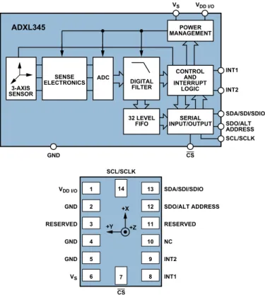
Figure 1 shows the system block diagram and pin definitions of the ADXL345. 3-AXIS SENSOR SENSE ELECTRONICS DIGITAL FILTER ADXL345 SERIAL INPUT/OUTPUT INT1 INT2 SDA/SDI/SDIO SDO/ALT ADDRESS SCL/SCLK GND ADC 32 LEVEL FIFO POWER MANAGEMENT CONTROL AND INTERRUPT LOGIC VS VDD I/O CS 14 SCL/SCLK 7 1 2 3 4 5 6 VDD I/O GND RESERVED GND GND VS SDA/SDI/SDIO SDO/ALT ADDRESS RESERVED NC INT2 INT1 13 12 11 10 9 8 CS +Z +X +Y
Figure 1. ADXL345 system block diagram and pin designations.
The ADXL345 features two programmable interrupt pins—INT1 and INT2—with a total of eight interrupt functions available. Each interrupt can be enabled or disabled independently, with the option to map to either the INT1 or INT2 pin. All functions can be used simultaneously—the only limiting feature is that some functions may need to share interrupt pins. The eight functions are: DATA_READY, SINGLE_TAP, DOUBLE_TAP, ACTIVITY, INACTIVITY, FREE_FALL, WATERMARK, and OVERRUN. Interrupts are enabled by setting the appropriate bit in the INT_ENABLE register and are mapped to either the INT1 or INT2 pins, based on the contents of the INT_MAP register. The interrupt functions are defined as follows:
1. DATA_READY is set when new data is available—and cleared when no new data is available.
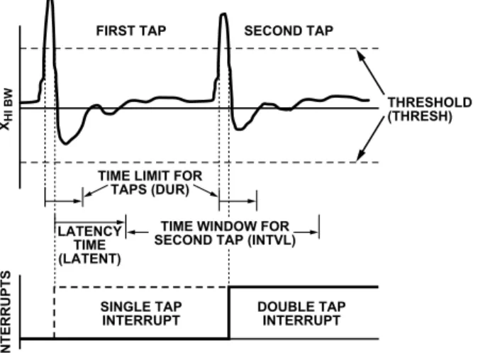
2. SINGLE_TAP is set when a single acceleration event that is greater than the value in the THRESH_TAP register occurs for a shorter time than specified in the DUR register. 3. DOUBLE_TAP is set when two acceleration events that are
greater than the value in the THRESH_TAP register occur and are shorter than the time specified in the DUR register, with the second tap starting after the time specified by the LATENT register and within the time specified in the WINDOW register.
Figure 2 illustrates the valid SINGLE_TAP and DOUBLE_TAP interrupts.
FIRST TAP
TIME LIMIT FOR TAPS (DUR) LATENCY
TIME (LATENT)
TIME WINDOW FOR SECOND TAP (INTVL)
SECOND TAP
SINGLE TAP
INTERRUPT DOUBLE TAPINTERRUPT
THRESHOLD (THRESH)
XHI BW
INTERRUPTS
Figure 2. SINGLE_TAP and DOUBLE_TAP interrupts. 4. ACTIVITY is set when acceleration greater than the value
stored in the THRESH_ACT register is experienced. 5. INACTIVITY is set when acceleration of less than the value
stored in the THRESH_INACT register is experienced for longer than the time specified in the TIME_INACT register. The maximum value for TIME_INACT is 255 s.
Note: With ACTIVITY and INACTIVITY interrupts, the user can enable or disable each axis individually. For example, the ACTIVITY interrupt for the X-axis can be enabled while disabling the interrupts for the Y-axis and Z-axis.
Furthermore, the user can select between dc-coupled or ac-coupled operation mode for the ACTIVITY and INACTIVITY interrupts. In dc-coupled operation, the current acceleration is compared with THRESH_ACT and THRESH_ INACT directly to determine whether ACTIVITY or INACTIVITY is detected. In ac-coupled operation for activity detection, the acceleration value at the start of activity detection is taken as a reference value. New samples of acceleration are then compared to this reference value; if the magnitude of the difference exceeds THRESH_ACT, the device will trigger an ACTIVITY interrupt. In ac-coupled operation for inactivity detection, a reference value is used for comparison and is updated whenever the device exceeds the inactivity threshold. Once the reference value is selected, the device compares the magnitude of the difference between the reference value and the current acceleration with THRESH_INACT. If the difference is below THRESH_INACT for a total of TIME_INACT, the device is considered inactive and the INACTIVITY interrupt is triggered.
6. FREE_FALL is set when acceleration of less than the value stored in the THRESH_FF register is experienced for longer than the time specified in the TIME_FF register. FREE_FALL interrupt is mainly used in detection of free-falling motion. As a result, the FREE_FALL interrupt differs from the INACTIVITY interrupt in that all axes always participate, the timer period is much shorter (1.28 s maximum), and it is always dc-coupled.
7. WATERMARK is set when the number of samples in the FIFO has filled up to the value stored in the SAMPLES register. It is cleared automatically when the FIFO is read
and its content emptied below the value stored in the SAMPLES register.
Note: the FIFO register in the ADXL345 has four operation modes: Bypass, FIFO, Stream, and Trigger; and can store up to 32 samples (X-, Y-, and Z-axis). The FIFO function is an important and very useful feature; however, the proposed solution does not use the FIFO function, so it will not be further discussed.
8. OVERRUN is set when new data has replaced unread data. The precise operation of OVERRUN depends on the operation mode of FIFO. In bypass mode, OVERRUN is set when new data replaces unread data in the DATAX, DATAY, and DATAZ registers. In all other modes, OVERRUN is set when the FIFO is filled with 32 samples. OVERRUN is cleared by reading the FIFO contents and is automatically cleared when the data is read.
Acceleration-Change Characteristics While Falling
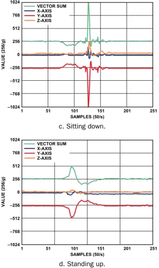
The main research on the principles of fall detection focuses on the changes in acceleration that occur when a human is falling. Figure 3 illustrates changes in acceleration that occur when (a) walking downstairs, (b) walking upstairs, (c) sitting down, and (d) standing up from a chair. The fall detector is mounted to a belt on the individual’s body. The red trace is the Y-axis (vertical) acceleration; it is –1 g at equilibrium. The black and yellow traces are the respective X-axis (forward) and Z-axis (sideways) accelerations. They are both 0 g at equilibrium. The green trace is the vector sum magnitude, 1 g at equilibrium.
–1024 –768 –512 –256 0 256 512 768 1024 1 51 101 151 201 251 301 351 401 VALUE (256/ g ) SAMPLES (50/s) VECTOR SUM Z-AXIS X-AXIS Y-AXIS a. Walking downstairs. –1024 –768 –512 –256 0 256 512 768 1024 1 51 101 151 201 251 301 351 401 VALUE (256/ g ) SAMPLES (50/s) VECTOR SUM Z-AXIS X-AXIS Y-AXIS b. Walking upstairs.
–1024 –768 –512 –256 0 256 512 768 1024 1 51 101 151 201 251 VALUE (256/ g ) SAMPLES (50/s) VECTOR SUM Z-AXIS X-AXIS Y-AXIS c. Sitting down. –1024 –768 –512 –256 0 256 512 768 1024 1 51 101 151 201 251 VALUE (256/ g ) SAMPLES (50/s) VECTOR SUM Z-AXIS X-AXIS Y-AXIS d. Standing up.
Figure 3. Accelerometer responses to different types of motion. Because the movement of elderly people is comparatively slow, the acceleration change will not be very conspicuous during the walking motions. The most pronounced acceleration is a 3-g spike in Y (and the vector sum) at the instant of sitting down.
The accelerations during falling are completely different. Figure 4 shows the acceleration changes during an accidental fall. By comparing Figure 4 with Figure 3, we can see four critical differences characteristic of a falling event that can serve as the criteria for fall detection. They are marked in the red boxes and explained in detail as follows:
4 1 3 2 1: WEIGHTLESSNESS 2: IMPACT 3: MOTIONLESS 4: INITIAL STATUS –512 –256 0 256 512 768 1024 1 51 101 151 201 VALUE (256/ g ) SAMPLES (50/s) VECTOR SUM Z-AXIS X-AXIS Y-AXIS
Figure 4. Acceleration change curves during the process of falling.
1. Start of the fall: The phenomenon of weightlessness will always occur at the start of a fall. It will become more significant during free fall, and the vector sum of acceleration will tend toward 0 g; the duration of that condition will depend on the height of freefall. Even though weightlessness during an ordinary fall is not as significant as that during a freefall, the vector sum of acceleration will still be substantially less than 1 g (while it is generally greater than 1 g under normal conditions). Therefore, this is the first basis for determining the fall status that could be detected by the ADXL345’s FREE_FALL interrupt.
2. Impact: After experiencing weightlessness, the human body will impact the ground or other objects; the acceleration curve shows this as a large shock. This shock is detected by the ACTIVITY interrupt of ADXL345. Therefore, the second basis for determining a fall is the ACTIVITY interrupt right after the FREE_FALL interrupt.
3. Aftermath: Generally speaking, the human body, after falling and making impact, can not rise immediately; rather it remains in a motionless position for a short period (or longer as a possible sign of unconsciousness). On the acceleration curve, this presents as an interval of flat line, and is detected by the INACTIVITY interrupt of ADXL345. Therefore, the third basis for determining a fall situation is the INACTIVITY interrupt after the ACTIVITY interrupt. 4. Comparing before and after: After a fall, the individual’s
body will be in a different orientation than before, so the static acceleration in three axes will be different from the initial status before the fall (Figure 4). Suppose that the fall detector is belt-wired on the individual’s body, to provide the entire history of acceleration, including the initial status. We can read the acceleration data in all three axes after the INACTIVITY interrupt and compare those sampling data with the initial status. In Figure 4, it is evident that the body fell on its side, since the static acceleration has changed from –1 g on the Y axis to +1 g on the Z-axis. So the fourth basis for determining a fall is if the difference between sampling data and initial status exceeds a certain threshold, for example, 0.7 g.
The combination of these qualifications forms the entire fall-detection algorithm, which, when exercised, can cause the system to raise an appropriate alert that a fall has occurred. Of course, the time interval between interrupts has to be within a reasonable range. Normally, the time interval between FREE_FALL interrupt (weightlessness) and ACTIVITY interrupt (impact) is not very long unless one is falling from the top of a very high building! Similarly, the time interval between ACTIVITY interrupt (impact) and INACTIVITY interrupt (essentially motionless) should not be very long. A practical example will be given in the next section with a set of reasonable values. The related interrupt detection threshold and time parameters can be flexibly set as needed.
If a fall results in serious consequences, such as unconsciousness, the human body will remain motionless for an even longer period of time, a status that can still be detected by the INACTIVITY interrupt, so a second critical alert could be sent out if the inactive state was detected to continue for a defined long period of time after a fall.
Typical Circuit Connection
The circuit connection between the ADXL345 and a microcontroller is very simple. For this article, the test platform uses the ADXL345 and an ADuC7026 analog microcontroller—which features 12-bit
analog I/O and an ARM7TDMI® MCU. Figure 5 shows the
typical connection between ADXL345 and ADuC7026.2 With
the CS pin of ADXL345 tied high, the ADXL345 works in I2C
mode. The SDA and SCL, the data and clock of the I2C bus, are
connected to the corresponding pins of ADuC7026. A GPIO of ADuC7026 is connected to the ADXL345’s ALT pin to select the I2C address of the ADXL345, and the INT1 pin of ADXL345
is connected to an IRQ input of the ADuC7026 to generate the interrupt signal.
Other MCU or processor types could be used to access the ADXL345, with similar circuit connections to Figure 5, but the ADuC7026 also provides a data-acquisition facility including
multichannel analog-to-digital and digital-to-analog conversion. The ADXL345 data sheet describes SPI-mode applications to achieve higher data rates.
Using the ADXL345 to Simplify Fall Detection
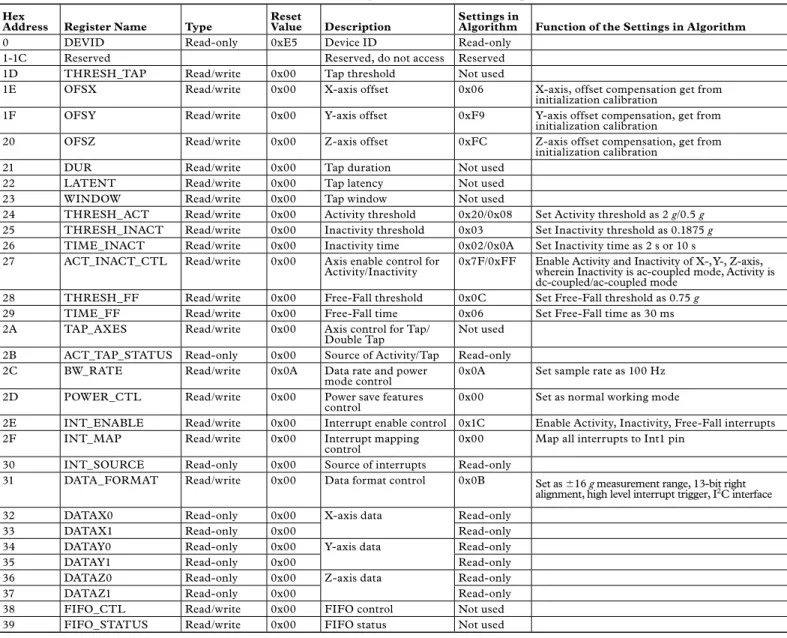
Table 1, Figure 5, and the Appendix define the realization of the algorithm for the solution mentioned above. The function of each register is included in the table, and the values used in the present algorithm are as indicated. Please refer to the ADXL345 data sheet for the detailed definition of each register bit.
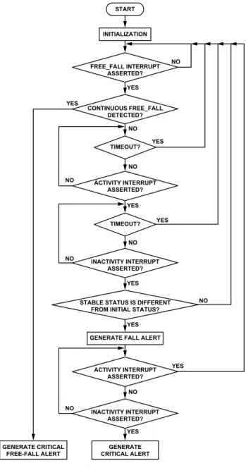
Some of the registers in Table 1 will have two values. This indicates that the algorithm switches between these values for different aspects of detection. Figure 6 is an algorithm flow chart.
ADXL345 VS CS SDA/SDI/SDIO SDA SCL/SCLK SCL SDO/ALT ADDRESS GPIO INT1 IRQ GND GND VDD I/O VDD 3.3V ADuC7026
Figure 5. Typical circuit connection between the ADXL345 and microcontroller.
Table 1. ADXL345 Registers Function Descriptions
Hex
Address Register Name Type Reset Value Description Settings in Algorithm Function of the Settings in Algorithm
0 DEVID Read-only 0xE5 Device ID Read-only
1-1C Reserved Reserved, do not access Reserved
1D THRESH_TAP Read/write 0x00 Tap threshold Not used
1E OFSX Read/write 0x00 X-axis offset 0x06 X-axis, offset compensation get from
initialization calibration
1F OFSY Read/write 0x00 Y-axis offset 0xF9 Y-axis offset compensation, get from
initialization calibration
20 OFSZ Read/write 0x00 Z-axis offset 0xFC Z-axis offset compensation, get from
initialization calibration
21 DUR Read/write 0x00 Tap duration Not used
22 LATENT Read/write 0x00 Tap latency Not used
23 WINDOW Read/write 0x00 Tap window Not used
24 THRESH_ACT Read/write 0x00 Activity threshold 0x20/0x08 Set Activity threshold as 2 g/0.5 g
25 THRESH_INACT Read/write 0x00 Inactivity threshold 0x03 Set Inactivity threshold as 0.1875 g
26 TIME_INACT Read/write 0x00 Inactivity time 0x02/0x0A Set Inactivity time as 2 s or 10 s
27 ACT_INACT_CTL Read/write 0x00 Axis enable control for
Activity/Inactivity 0x7F/0xFF Enable Activity and Inactivity of X-, Y-, Z-axis, wherein Inactivity is ac-coupled mode, Activity is dc-coupled/ac-coupled mode
28 THRESH_FF Read/write 0x00 Free-Fall threshold 0x0C Set Free-Fall threshold as 0.75 g
29 TIME_FF Read/write 0x00 Free-Fall time 0x06 Set Free-Fall time as 30 ms
2A TAP_AXES Read/write 0x00 Axis control for Tap/
Double Tap Not used
2B ACT_TAP_STATUS Read-only 0x00 Source of Activity/Tap Read-only
2C BW_RATE Read/write 0x0A Data rate and power
mode control 0x0A Set sample rate as 100 Hz
2D POWER_CTL Read/write 0x00 Power save features
control 0x00 Set as normal working mode
2E INT_ENABLE Read/write 0x00 Interrupt enable control 0x1C Enable Activity, Inactivity, Free-Fall interrupts
2F INT_MAP Read/write 0x00 Interrupt mapping
control 0x00 Map all interrupts to Int1 pin
30 INT_SOURCE Read-only 0x00 Source of interrupts Read-only
31 DATA_FORMAT Read/write 0x00 Data format control 0x0B Set as ±16 g measurement range, 13-bit right alignment, high level interrupt trigger, I2C interface
32 DATAX0 Read-only 0x00 X-axis data Read-only
33 DATAX1 Read-only 0x00 Read-only
34 DATAY0 Read-only 0x00 Y-axis data Read-only
35 DATAY1 Read-only 0x00 Read-only
36 DATAZ0 Read-only 0x00 Z-axis data Read-only
37 DATAZ1 Read-only 0x00 Read-only
38 FIFO_CTL Read/write 0x00 FIFO control Not used
START INITIALIZATION NO NO YES YES YES YES YES YES YES YES YES NO NO NO NO NO NO NO FREE_FALL INTERRUPT ASSERTED? ACTIVITY INTERRUPT ASSERTED? ACTIVITY INTERRUPT ASSERTED? INACTIVITY INTERRUPT ASSERTED? INACTIVITY INTERRUPT ASSERTED? STABLE STATUS IS DIFFERENT
FROM INITIAL STATUS? TIMEOUT?
GENERATE FALL ALERT
GENERATE CRITICAL ALERT GENERATE CRITICAL FREE-FALL ALERT CONTINUOUS FREE_FALL DETECTED? TIMEOUT?
Figure 6. Algorithm flow chart.
Each interrupt threshold, and the related time parameter in the algorithm, is as described below.
1. After initialization, the system waits for the FREE_FALL interrupt (weightlessness). Here THRESH_FF is set to 0.75 g and TIME_FF is set to 30 ms.
2. After FREE_FALL interrupt is asserted, the system begins
waiting for the ACTIVITY interrupt (impact). THRESH_ACT is set to 2 g and the ACTIVITY interrupt is in dc-coupled mode. 3. Ti me i nter va l bet we en F R E E _ FA L L i nter r upt
(weightlessness) and ACTIVITY interrupt (impact) is set to 200 ms. If the time between these two interrupts is greater than 200 ms, the status is not valid. The 200-ms counter is realized through the MCU timer.
4. After the ACTIVITY interrupt is asserted, the system begins waiting for the INACTIVITY interrupt (motionless after impact). THRESH_INACT is set to 0.1875 g and TIME_INACT is set to 2 s. INACTIVITY interrupt works in ac-coupled mode.
5. The INACTIVITY interrupt (motionless after impact) should be asserted within 3.5 s after the ACTIVITY interrupt (impact). Otherwise, the result is invalid. The 3.5-s counter is realized through the MCU timer.
6. If the acceleration difference between stable status and initial status exceeds the 0.7-g threshold, a valid fall is detected, and the system will raise a fall alert.
7. After detecting a fall, the ACTIVITY interrupt and INACTIVITY interrupt have to be continuously monitored to determine if there is a long period of motionlessness after the fall. The THRESH_ACT is set to 0.5 g and the ACTIVITY interrupt is running in the ac-coupled mode. THRESH_INACT is set to 0.1875 g, TIME_INACT is set to 10 s, and the INACTIVITY interrupt is working in ac-coupled mode. In other words, if the subject’s body remains motionless for 10 s the INACTIVITY interrupt will be asserted and the system raises a critical alert. Once the subject’s body moves, the ACTIVITY interrupt will be generated to complete the entire sequence.
8. The algorithm can also detect if the individual’s body freefalls from a high place. Here, we consider that the two FREE_FALL interrupts are continuous if the interval between them is shorter than 100 ms. A critical freefall alert will be raised if the FREE_FALL interrupt (weightlessness) is continuously asserted for 300 ms
.
This algorithm is developed in C language to be executed on the ADuC7026 microcontroller (See Appendix). A test case is also presented with the proposed solution to verify the algorithm. Each position, including falling forward, falling backward, falling to the left, and falling to the right is tested 10 times. Table 2 presents the test results. Check marks () indicate each condition that is satisfied.
Table 2. Test Results
Falling Position Prolonged Motionless Period after Falling 1 2 3 4 5 6 7 8 9 10
Falling Forward No
Yes
*
*
*
*
*
*
*
*
*
*
Falling Backward No
Yes
*
*
*
*
*
*
*
*
*
*
Falling to the Left No
Yes
*
*
*
*
*
*
*
*
*
*
Falling to the Right No
Yes
*
*
*
*
*
*
*
*
*
*
Note: The symbol indicates a detected fall; the * symbol indicates a detected prolonged motionless period after falling.This experiment shows that falling status can be effectively detected with the proposed solution, based on the ADXL345. This is only a simple experiment. More comprehensive, effective, and long-term experimentation will be required to verify the reliability of the proposed solution.
Conclusion
The ADXL345 is a powerful and full-featured accelerometer. We have described a proposed new solution for the fall-detection problem that takes advantage of the various built-in motion-status detection features and flexible interrupts. Tests have shown that it combines low algorithm complexity and high detection accuracy. APPENDIX—An Example of the Code
Please contact Analog Devices at www.analog.com or Ning Jia [[email protected]] regarding C code examples.
The Author
Ning Jia [ni ng.jia@a nalog.com], a field applications engineer, has been a member of the Analog Devices China Applications Support Team for two years. He is responsible for the technical support of a broad range of analog products across China. He graduated in 2007 from Beijing University of Posts and Telecommunications with a master’s degree in signal and information processing. References
1 Information on all A DI components can be found at
www.analog.com.
2www.analog.com/en/analog-microcontrollers/ADuC7026/