c
BREAKING SERIALIZATION IN LOCK-FREE MULTICORE SYNCHRONIZATION
BY
TANMAY GANGWANI
THESIS
Submitted in partial fulfillment of the requirements
for the degree of Master of Science in Electrical and Computer Engineering in the Graduate College of the
University of Illinois at Urbana-Champaign, 2016
Urbana, Illinois Advisor:
ABSTRACT
In multicores, performance-critical synchronization is increasingly performed in a lock-freemanner using atomic instructions such as CAS or LL/SC. How-ever, when many processors synchronize on the same variable, performance can still degrade significantly. Contending writes get serialized, creating a non-scalable condition. Past proposals that build hardware queues of syn-chronizing processors do not fundamentally solve this problem—at best, they help to efficiently serialize the contending writes.
We propose a novel architecture that breaks the serialization of hardware queues and enables the queued processors to perform lock-free synchroniza-tion in parallel. The architecture, called Caspar, is able to (1) execute the CASes in the queued-up processors in parallel through eager forwarding of expected values, and (2) validate the CASes in parallel and dequeue groups of processors at a time. The result is highly scalable synchronization. We evaluate Caspar with simulations of a 64-core chip. Compared to existing proposals with hardware queues,Casparimproves the throughput of kernels by 32% on average and reduces the execution time of the sections considered in lock-free versions of applications by 47% on average. This makes these sections 2.5x faster than in the original applications.
ACKNOWLEDGMENTS
I am extremely grateful to my advisor, Josep Torrellas, for his amazing insights and constant encouragement throughout my thesis project. I am equally indebted to Adam Morrison for being a wonderful collaborator. Adam’s out-of-the-box thinking is as remarkable as it is inspiring. I feel fortunate to have been a part of numerous brainstorming sessions with Josep and Adam. My journey would have been rough without support from two special groups. Firstly, my research ensemble—the i-acoma group—which was a perennial source of prudent advise, technical debates and delightful conver-sations. A shout-out to Aditya Agarwal and other seniors who never made me feel that home was far away. “Chambana Dwellers” (CD) is the other group that I hold very dear. It’s an eclectic mix of five people—you know who you are—from different parts of India, each weird in their own, irrepro-ducible ways. This group was my life outside of Siebel Center. Jim Rohn famously said that you are average of the five people you spend the most time with. Thank you CD for filling that part for me. I love you!
I would be amiss if I didn’t mention the other friends I made at UIUC— my classmates, apartment buddies etc. There’s something to learn from everyone; thanks for bringing about a positive change in me. I am blessed to have a gem of a brother to fall back on for anything. Last but not the least, my parents have been, and will always be, my pillars of strength. You two are simply the best!
TABLE OF CONTENTS
LIST OF TABLES . . . vi
LIST OF FIGURES . . . vii
CHAPTER 1 INTRODUCTION . . . 1
CHAPTER 2 BACKGROUND . . . 4
2.1 Lock-free Synchronization . . . 4
2.2 Performance Bottlenecks . . . 4
CHAPTER 3 OVERVIEW OF CASPAR . . . 7
3.1 A LIFO Stack Example . . . 7
3.2 Caspar Ideas . . . 9
3.3 Caspar Effectiveness . . . 10
CHAPTER 4 CASPAR ARCHITECTURE . . . 12
4.1 Identifying Contended CAS Locations . . . 13
4.2 Efficiently Queueing-up Concurrent CASes . . . 14
4.3 Parallel CAS Execution through Eager Forwards . . . 16
4.4 Parallel CAS Validation using Group Commits . . . 22
CHAPTER 5 EVALUATION . . . 28
5.1 Experimental Setup . . . 28
5.2 Kernels . . . 30
5.3 Applications . . . 33
CHAPTER 6 DESIGN EXTENSIONS . . . 35
CHAPTER 7 RELATED WORK . . . 36
7.1 Transactional Memory . . . 36
7.2 Hardware Support for Scalable Synchronization . . . 36
CHAPTER 8 CONCLUSION . . . 37
LIST OF TABLES
4.1 Components of Caspar. . . 12 5.1 Architecture simulated. . . 28 5.2 Programs evaluated. . . 29
LIST OF FIGURES
3.1 Treiber’s lock-free LIFO stack. . . 7
3.2 Ideas behindCaspar. . . 8
4.1 Basic hardware structures in Caspar. . . 13
4.2 Timeline to enforce Load-to-CAS atomicity. . . 14
4.3 Timeline to queue/dequeue requests. . . 15
4.4 Operation of eager forwarding. . . 18
4.5 Additional hardware for eager forwarding (a) and parallel CAS validation (b). . . 20
4.6 Timeline to perform eager forwarding. . . 20
4.7 Forwarding causes no consistency violation. . . 22
4.8 Parallel CAS validation. . . 24
4.9 Timeline of parallel CAS validation. . . 27
5.1 Kernel throughput for the different designs. . . 30
5.2 Impact of work size (a-c) and scalability (d-f). . . 31
5.3 Cycle breakdown for EF and C. The numbers at the top of the bars are the CAS throughput. . . 32
CHAPTER 1
INTRODUCTION
The arrival of large multicores such as Intel’s Xeon Phi [1] provides renewed impetus to develop highly threaded applications that share data in a fine-grained manner. Examples of such applications can be found in the tradi-tional domains of numerical and database [2, 3] computing, as well as in the runtimes of emerging programming frameworks, such as Galois [4] for graph analytics, and those of Google’s Go [5] and Mozilla’s Rust [6] languages.
Fine-grained applications require efficient synchronization to manage shared data structures. For highest performance, they often employ lock-free syn-chronization [7], which avoids the overheads of using locks [8, 2, 9, 10, 11, 12, 13, 3]. Lock-free synchronization forgoes locking by directly manipulat-ing the data structures usmanipulat-ing atomic instructions such as compare-and-swap (CAS) or load-linked/store-conditional (LL/SC). There are several popular lock-free versions of basic data structures, such as queues [14, 15], stacks [16], LRU caches [17], and priority queues [18]. They provide fast operations on these structures.
Regrettably, while lock-free synchronization provides fast sequential access to shared structures, many-thread synchronization can still lead to substan-tial contention—e.g., when all the threads attempt to perform a CAS on the head of a queue to update it atomically. For this reason, developers of highly threaded codes today turn to algorithms that distribute synchroniza-tion [19, 20, 21, 22, 4, 23].
Unfortunately, these algorithms are difficult to design and debug. Even more importantly, they often provide only weak and unintuitive data struc-ture semantics [19, 20, 21, 23]—e.g., items in a distributed queue are removed in an order that is different than their insertion order. Such weak semantics make these distributed algorithms more error-prone and difficult to use, and render them inappropriate for programs that require familiar semantics.
the synchronizing processors in hardware [24, 25, 26, 27, 28, 29, 30]. Other designs have also proposed to forward or prefetch [27, 31] the data accessed in the critical section when a lock is transferred. These proposals attempt to
efficiently serialize concurrent synchronizations. However, they do not solve the serialization problem itself: serialized writes inherently become slower as the number of synchronizing processors grows. To make synchronization truly scalable, we need to break the serialization of the queue and allow the queued processors to synchronize in parallel.
This work proposes a novel architecture design thatbreaksthe serialization of hardware queues and enables the queued processors to perform lock-free synchronization in parallel. The scheme, called Caspar, is applicable to some common lock-free synchronization patterns. The result is low-overhead, highly-scalable synchronization. With Caspar, it is possible to have non-distributed scalable versions of lock-free data structures.
We presentCasparin the context of the CAS instruction, although it also applies to other synchronization instructions such as LL/SC. Recall that a CAS takes three operands: a memory address addr, an old value, and a new
value. A CAS changes the value in addr to new, provided the current value in addr is old. We observe that, in common synchronization patterns, the
newvalue that a processor stores on a variable with a CAS does not depend on theold value previously read from the variable. Instead, thenewvalue is generated locally by the processor. For example, as we will see, this occurs when pushing nodes into a stack.
This observation motivatesCaspar, which exploits it with two new ideas: (i) parallel execution of the CASes in the queued-up processors through eager forwarding of the expected new values, and (ii) parallel validation of the CASes and group dequeue of the processors.
The first idea uses the fact that a queued processor may know early on the new value to which it will set the shared variable. Hence, it eagerly forwards it to its immediate successor in the queue, so that the successor processor can use it as its old value. As a result, queued processors can perform their CASes early on and in parallel, and continue execution past the CAS. However, since the value passed is a hint, the successors’ execution becomes speculative.
The second idea involves the group validation of CASes and, therefore, the group commit and dequeue of processors. It leverages the fact that the
directory knows the values passed between processors and can interrogate a chain of dependent processors in parallel. If all processors validate, a two-phase commit operation dequeues them all in one step.
Caspar effectiveness. We evaluate Caspar by augmenting a simulated 64-core multicore with a synchronization hardware queue (representing prior work) and then extending it with the complete Caspardesign. We run five kernels and several applications—including some from the Galois system [4]. The applications are modified to use lock-free data structures. Compared to the design with only the hardware queue,Caspar: (i) improves the through-put of the kernels by 32% on average, and (ii) reduces the execution time of the sections considered in the lock-free applications by 47% on average. This makes such sections 2.5x faster than in the original, tuned versions. Also, compared to a design with only conventional CAS synchronization, Caspar improves the kernel throughput by 83% and reduces the execution time of the application sections by 58% on average.
Overall, the contributions of this work are:
• The Caspar architecture, which provides scalable and efficient lock-free synchronization by parallelizing the operation of hardware-queued proces-sors.
• A design for automatically triggering hardware queueing on the unmarked loads of contended CAS variables.
• Simulation-based evaluation of Casparusing highly threaded kernels and applications.
CHAPTER 2
BACKGROUND
2.1
Lock-free Synchronization
Lock-free synchronization (also referred to asnonblockingsynchronization [32]) directly manipulates shared data using atomic instructions such as CAS and LL/SC, or transactional memory (TM) instead of using locks (see Chapter 3 for an example). Performance-critical multi-threaded codes such as operating systems [33, 8, 10], databases [34, 2, 3], language runtimes [9], memory allo-cators [11, 12, 13], or trading frameworks [35] often utilize lock-free synchro-nization to avoid the overheads of locking. Also, lock-free synchrosynchro-nization is popularized by standard libraries, such as Java’s concurrency package [36] and C++ Boost [37], which provide lock-free data structures as black boxes for programmers to use.
Lock-free synchronization has two main performance advantages compared to lock-based solutions. First, it is more efficient, since it has no lock acquire and release operations on the critical path. Indeed, lock-free versions of many basic data structures have fast synchronization operations that write to at most a few variables—queues [14, 38, 39], stacks [40], and priority queues [41, 42]. Second, lock-free algorithms guarantee system-wide progress, and thus eliminate problems such as deadlocks and preemption of the holder of a lock [32].
2.2
Performance Bottlenecks
Lock-free synchronization still has two performance issues when many pro-cessors contend to perform a write to the same synchronization variable. First, sometimes CAS or LL/SC atomic instructions fail, and transactions
abort. This can place useless work on the critical path. Second, contend-ing writes are serialized, as each processor must obtain exclusive access to the contended variable’s cache line to update it. This serialization causes the latency of each write to grow with the amount of concurrency, making contending writes non-scalable and slow.
2.2.1
Software approaches
To avoid these issues, developers turn to algorithms that distribute synchro-nization [19, 20, 21, 22, 4, 23]. However, these algorithms are often complex and provide only weak and unintuitive data structure semantics [19, 20, 21, 23]. For example, consider a FIFO queue algorithm. Instead of synchroniz-ing all operations on a ssynchroniz-ingle queue head, we distribute the synchronization. We maintain a queue per producer thread and require a remove operation to iterate over each of these queues until it finds an item to remove [20]. Doing so, however, no longer maintains the cause and effect relation in the pro-gram: If thread T1 addsx1 to its queue after thread T0 adds x0 to its queue,
a remove can return x1 beforex0. Weweakened the guarantees provided by
the queue from global FIFO to per-thread FIFO. Thus, to work around the bottlenecks of existing hardware, we burden software with semantically weak data structures.1 Worse, data structures with weak semantics simply
can-not be used in some cases—e.g., as message-passing channels in actor-based programming languages [43].
2.2.2
Hardware approaches
Alternatively, there are hardware proposals to make synchronization efficient (Chapter 7). The most relevant to our work are those that build hardware queues of processors synchronizing on a variable. Specifically, Goodman et al. [24, 25] proposed QOSB/QOLB, which forms a hardware queue link-ing the caches of the synchronizlink-ing processors. Hardware queues have also been implemented in the directory of DASH [28], and proposed by other researchers [26, 27, 30, 29]. In one of these designs [26], coherence actions 1Quoting Shavit [23]: “requirements placed on the data structures will have to be relaxed in order to
are delayed to prevent repeated failure of lock acquire or atomic instruc-tions. Specifically, a processor delays responding to requests on the syn-chronization variable while the processor is executing the critical section or the code between LL and SC. Finally, other designs proposed to forward or prefetch [27, 31] the data accessed in a critical section while the lock is transferred.
These proposals efficiently serialize concurrent synchronizations. However, they do not solve the serialization problem itself: executing the critical sec-tion or performing the lock-free write takes on average proporsec-tionally longer as the number of synchronizing processors grows.
2.2.3
Our approach and observation
To make synchronization truly scalable, we need hardware that breaks the queue serialization and allows the queued processors to synchronize in par-allel. To design this hardware, we observe that, in some common synchro-nization patterns that we describe in the next section, the newvalue that a CAS writes to a variable does not depend on the variable’s previous value.
CHAPTER 3
OVERVIEW OF
CASPAR
3.1
A LIFO Stack Example
Figure 3.1 shows the C code of Treiber’s lock-free LIFO stack [40]. As shown in Figure 3.1(a), the stack is a linked list of nodes, each of which holds a value. The top of the stack is the first node in the list. The push() (Figure 3.1(b)) and pop() (Figure 3.1(c)) operations use a CAS.
1 // Stack consists of linked list of nodes.
2 // The following defines a stack node:
3 structNode{
4 structNode∗next;
5 void∗value;
6 }
7 // Pointer to top of the stack , initially
8 // NULL as the stack is empty:
9 Node∗stack= NULL; (a) Definitions
10 void push(void∗v){
11 Node∗old top,∗new top = malloc();
12 new top−>value = v;
13 while(true){
14 old top =stack;
15 new top−>next = old top;
16 if (CAS(&stack, old top, new top))
17 return;
18 } }
(b) Pushing a value
19 void∗pop(){
20 Node∗old top,∗new top;
21 while(true){
22 old top =stack;
23 if (old top == NULL)returnNULL;
24 new top = old top−>next;
25 if (CAS(&stack, old top, new top))
26 returnold top−>value;
27 } }
(c) Popping a value
P0 old_top = stack P1 old_top = stack P0 new_top , Time Time Line 11: Line 14: Line 16: Line 11: Line 14: Line 16: P0 Stack P1 stack: stack: stack: (a) P0 new_top : P1 new_top : stack: Line 14: Line 11: Line 15: Line 16: P0 new_top : P1 new_top : P1 new_top : P0 P1 new new P2 (b) new CAS CAS ld(old) ld(old) ld(old)
ld(old) ld(old) CAS Stall Stall P0 P1 P2 new new CAS new ld(old) ld(old) ld(old)
Specul. Specul. Directory Time (d) P0 P1 P2 Time (c) new new CAS new ld(old) ld(old) ld(old)
Specul.
Speculative
CAS CAS CAS CAS
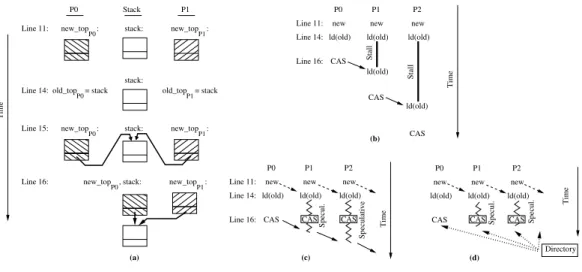
Figure 3.2: Ideas behind Caspar.
We focus on the push() operation. It allocates a new node, new top
(Line 11), whose next field is set to point to the current top of the stack,
old top (Lines 14–15). It then uses a CAS to set the top of the stack to this
new top (Line 16). A CAS failure implies that another thread has modified the top of the stack, and so the push() operation retries the CAS using a freshly-read value of stack.
Figure 3.2(a) illustrates the above process. It shows the execution of two processors (P0 and P1) and the state of the stack. The top row corresponds to Line 11, where P0 allocates the new topP0 node and P1 allocates the
new topP1 node. The second row is for Line 14, where the processors set
their old topP0 and old topP1 to stack. The third row is for Line 15, where
the processors point new topP0→nextand new topP1→nexttostack. Finally,
the last row is for Line 16, where both P0 and P1 attempt the CAS but only P0 succeeds. Thenew topP0 node is inserted at the top of the stack, and P1
has to retry.
The ABA problem. An ABA problem [44] occurs when a thread reads the same value (e.g., A) from the stack location in Lines 14 and 16 and, in between the two reads, other threads update the location to a different value (e.g., B) and then back to A. The CAS in Line 16 succeeds, even though the atomicity of the load-to-CAS execution was violated. As in other works, for our design, we assume implementations that avoid this problem by not recycling a node as long as some thread holds a reference to it [41, 45, 46].
3.2
Caspar
Ideas
In the push() operation, the CAS of the successful processor (P0) writes
new topP0 to stack. Such a value does not depend on the value that P0 did
read from stack into old top. Instead, it is obtained locally by P0, early on, with a malloc(). Interestingly, this is the value that the failing processor (P1) will need to read into its ownold topwhen it wants to perform the next successful CAS. To summarize, each processor generates thenewvalue for its CAS locally and early on, and this is the value that its immediate successor will need to read as its old value to perform its own CAS. This provides an opportunity for parallelism.
Unfortunately, even the most aggressive proposals for hardware synchro-nization queues fail to take advantage of this opportunity. Indeed, assume a design based on any of the hardware queues described in Chapter 2, where requests are queued in hardware in the directory. Further, assume that, for highest efficiency, the load-to-CAS execution is designed to be atomic—i.e., a processor reads stack, prepares the new value, and then writes the new value with the CAS without any conflicting access allowed to interleave in the middle.
In this design, Figure 3.2(b) shows the execution timeline of three proces-sors (P0, P1, and P2). Assume that all three generate their new values at approximately the same time, and that they attempt to load old and queue up in the P0-P1-P2 order. P0 gets the oldvalue, while the others stall (thick lines). Only after P0 completes its CAS can P1’s load complete and return the current old value—even though it was available as the new value that P0 produced long ago. P2 suffers an even longer stall. The operation of the processors is completely serialized.
3.2.1
First idea: parallel CAS execution
Caspar’s first idea is parallel CAS execution, as shown in Figure 3.2(c). When a processor generates its new value locally and early on, we propose that it eagerly forwardsthe new value right away to its immediate successor in the queue (dashed arrows). A processor uses the received value as the response to its load for the old value, and has all the information to perform the CAS. Hence,the CASes are performed early on and in parallel. Since the
values forwarded may be incorrect under certain conditions, execution past the load becomes speculative (zig-zag lines), and can only commit after a validation step in the background (solid arrows). Such a step would require waiting until the processor reaches the head of the queue, and then verifying that the actual content of the variable matches the value of the earlier hint. In cases when the CAS pattern is not amenable to eager forwarding,Caspar reverts to the serialization of prior queue designs.
3.2.2
Second idea: parallel CAS validation
Caspar’s second idea is to validate groups of CASes in parallel and, there-fore, commit groups of processors at a time. This technique reduces the amount of work done speculatively and, hence, reduces the risk of squashes. It is shown in Figure 3.2(d). The idea is based on the observation that the directory knows the value that each processor forwarded early on to its suc-cessor. Hence, the directory can later interrogate a chain of queued processors in parallel (dotted lines), to see if the value that a processor’s CAS ended up generating is indeed equal to the value that the processor forwarded early on to its successor. If this is true for a group of processors that begins with the one at the queue head, the group is committed and dequeued in one shot.
3.3
Caspar
Effectiveness
Caspar is effective when queued processors can generate their new value early on, independently of theold value that they read. This pattern appears in several cases. The most common one is when inserting elements into a shared data structure, as in the push() operation of Figure 3.1(b). This pattern also appears when using atomic swap instructions (like x86’s XCHG), setting variables to fixed values, resetting variables (e.g., a counter), and detaching a list by swapping the head pointer with null.
Insertion-heavy scenarios occur in many workloads. For example, they arise in runtimes using a shared work queue for load-balancing task-based parallelism [47], when the task queue is populated, either initially or as part of a bulk-synchronous execution [4, 48]; in update-heavy OS data structures such as the reverse page map or pathname lookup cache [49]; in memory
al-locators when accessing the main heap [11, 12, 13]; in high-speed networking when enqueuing packets [8]; and in other cases.
We also believe that the Casparideas apply more broadly than lock-free code based on CAS or LL/SC, and can be used to break the serialization in TM. We defer exploration of this idea to future work.
Casparis not effective when thenewvalue created by a queued processor depends on the old value that the processor reads. This pattern occurs most commonly when removing elements from a shared data structure. An example is the pop() operation of Figure 3.1(c), where the new value of the stack is obtained by reading the node currently at the top of the stack and accessing itsnext field. It also occurs when inserting elements to a structure using ABA-tagging [44]—i.e., devoting some bits in pointers for a counter that each operation increments, to reduce the chance of an ABA problem. Incrementing such a counter creates a dependency. In all of these cases, Caspar reverts to the serialization present in prior queue designs.
CHAPTER 4
CASPAR
ARCHITECTURE
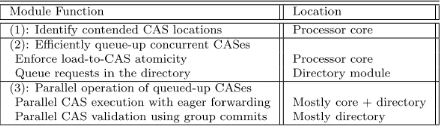
Caspar is composed of three modules, which (1) identify contended CASes, (2) efficiently queue concurrent CASes operating on a location, and (3) enable parallel operation of the queued-up CASes (i.e., the process that we called
breaking the serialization). Table 4.1 lists the modules and where they reside in the architecture. Since module (2) is reminiscent of previously proposed designs of hardware queues for synchronization (e.g., [24, 25, 28, 27]), we do not consider it a main contribution of this work. Hence, we only outline it briefly.
Table 4.1: Components of Caspar.
Module Function Location
(1): Identify contended CAS locations Processor core
(2): Efficiently queue-up concurrent CASes
Enforce load-to-CAS atomicity Processor core
Queue requests in the directory Directory module
(3): Parallel operation of queued-up CASes
Parallel CAS execution with eager forwarding Mostly core + directory
Parallel CAS validation using group commits Mostly directory
For ease of explanation, we divide module (2) into two parts: enforcing load-to-CAS atomicity and enqueuing requests in the directory. Module (3) is also composed of two parts: Parallel CAS Execution through eagerly for-warding, and Parallel CAS Validation using group commits. The following discussion assumes a generic chip multiprocessor (CMP) with a distributed directory for coherence.
4.1
Identifying Contended CAS Locations
4.1.1
Intuitive idea
Caspar dynamically identifies contended CAS locations in hardware, with-out the need to modify the executable. To understand how it works, consider a CAS such as the one in Line 16 of Figure 3.1(b). When it has failed a few times in a row, the Caspar hardware saves the address it contends on (i.e.,
stack) in a table. In addition, every load issued by the processor is dynami-cally checked against the entries in that table. When a load hits (such as the one in Line 14 of Figure 3.1(b)), the load becomes a Triggering Load (TL), which exercises the Caspar hardware. The Caspar hardware remains ac-tive until the corresponding CAS completes, at which point the hardware actions typically complete. In a processor, only a single load at a time can be exercising the Caspar hardware.
4.1.2
Detailed design
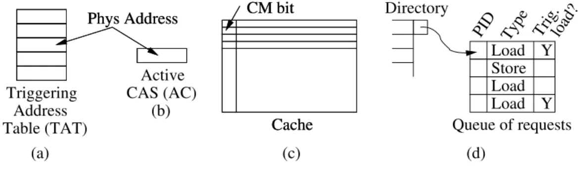
The two per-processor hardware structures used in this process are shown in Figures 4.1(a)-(b). One is the Triggering Addresses Table (TAT), which has the addresses identified as “under CAS contention” by this processor. It is a 4-8 entry, fully-associative table. Its entries are regularly aged out. The second structure is the Active CAS (AC), which can only contain one of the addresses from the TAT: the one currently exercising theCasparhardware.
(d) Queue of requests Y PID Type Load Load Load Store Trig.load? Y Directory (c) Cache CM bit Cache CM bit Phys Address Phys Address Triggering Address Table (TAT) Active (b) (a) CAS (AC)
Figure 4.1: Basic hardware structures in Caspar.
The address read by each load is compared to the addresses in the TAT. If a load hits and the AC is currently null, then the address read from is stored
in the AC and the load becomes a TL. Normally, the AC will retain its value until the corresponding CAS completes. Then, the AC is cleared. If a second load hits in the TAT while the AC is full, that load executes as a plain load (i.e., it is not a TL).
Caspar does not always need multiple CAS failures to insert an address in the TAT. We will see that a CAS that has encountered a queue in the directory returns a hint that can be used to insert the address accessed in the TAT.
4.2
Efficiently Queueing-up Concurrent CASes
4.2.1
Enforcing load-to-CAS atomicity
To support hardware queueing of concurrent CASes directed to the same ad-dress, Casparenforces Load-to-CAS atomicity. This is shown in Figure 4.2. A TL requests the memory line in Exclusive state. When the line arrives at the cache, the hardware sets a CAS Mode (CM) bit in the line’s cache tag (Figure 4.1(c)). The cache is now in CAS Mode, and rejects any incom-ing coherence requests for the line. The cache remains in CAS Mode until the corresponding CAS completes. If no CAS to the line executes within a timeout period (e.g., due to a bug), the CAS Mode expires. If an exception occurs, CM is cleared.
(1)
CAS
(2)
(3)
Triggering
load
in Exclusive state
Line in cache
CM = 1
Time
Incoming requests for the CM line are rejected
Figure 4.2: Timeline to enforce Load-to-CAS atomicity.
It is possible that two or more processors end up waiting on each other— e.g., if two processors execute load-to-CASes to different addresses, but, in between the load and the CAS, they attempt to access the address of the
other’s CAS location (or false-share it). The timeout mechanism avoids dead-lock. A similar timeout mechanism has been proposed for LL/SC [26].
4.2.2
Queueing requests in the directory
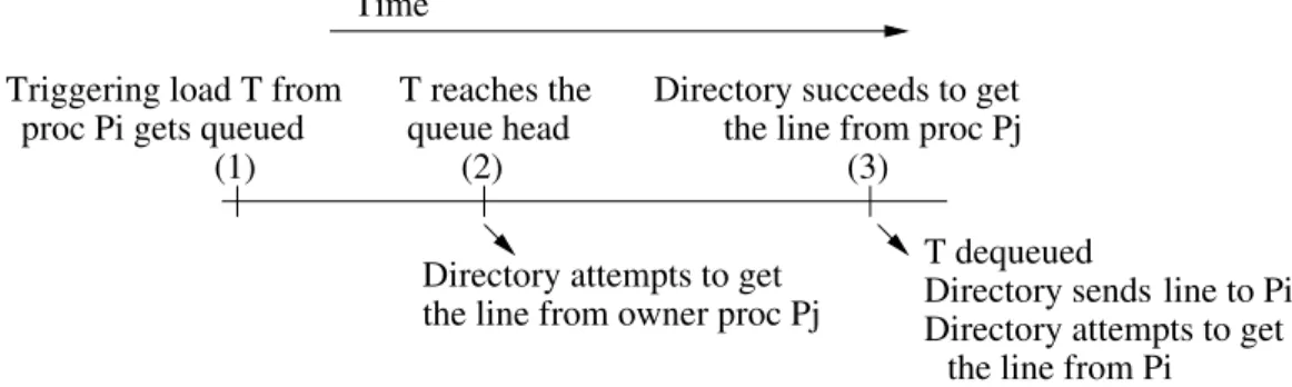
All the concurrent requesters to a given CAS location are queued up in hardware by Caspar in a directory module. As shown in Figure 4.3, when a TL request from processor Pi arrives at the directory, it is placed at the tail of the hardware queue. The directory continuously issues requests to the current owner of the line on behalf of the processor at the head of the queue. Such requests keep being rejected while the owner has its CM bit set in its cache line tag. When the owner clears the CM bit, the directory succeeds at stealing the line in Exclusive state and sends it to the processor at the head of the queue—as a response to its initial TL. Immediately after that, the directory dequeues the head entry from the directory queue and starts requesting the line from the new owner on behalf of the new entry at the head of the queue.
(2) (3)
(1)
Directory succeeds to get proc Pi gets queued
Time
T dequeued Directory attempts to get
the line from owner proc Pj
the line from proc Pj
Directory sends
Directory attempts to get the line from Pi
Triggering load T from T reaches the
queue head
line to Pi
Figure 4.3: Timeline to queue/dequeue requests.
Figure 4.1(d) shows the hardware queue. Logically, the directory entry for the contended CAS location has a pointer to the queue. Each queue entry records the requesting processor’s ID, the type of request (request to read or to write), and if the read is a TL. A directory module can have multiple queues for different addresses.
A queue entry of Store type is typically due to a CAS from a processor that is unaware that this location suffers contention. Hence, as indicated before, when the directory processes such an entry, it augments its reply to the requesting processor with a hint bit. If the access was indeed a CAS, this
bit prompts the requesting processor to save the address in its TAT (if it is not already there).
4.3
Parallel CAS Execution through Eager Forwards
Prior proposals that build a synchronization queue in hardware process the queue elements sequentially. Caspar processes them in parallel thanks to two ideas: (1) parallel CAS execution through eager forwarding and (2) parallel CAS validation using group commits. This section describes the first idea, the next one the other.
4.3.1
Intuitive idea
Caspar targets codes where the new value to store in the CASed location does not depend on theoldvalue in that location. WithCaspar, a processor Pi, before obtaining the line with the old value from memory, can forward its new value to the directory; the directory can send it to the successor processor Pi+1 in the queue. Pi+1 receives the value as a response to its TL
request for itsold value, and uses this highly accurate hint ofold in its CAS. Note that the forwarded value is coupled with its offset in the cache line, so Pi+1 uses it only if it matches its TL address. With this scheme, both
processors can execute the CAS in parallel.
Later, when Pi+1 reaches the head of the queue, the coherence protocol
supplies the line to Pi+1, as the true response to Pi+1’s TL. On reception
of the line, the hardware in Pi+1 compares the value in the line to the old
value that was received (and used) earlier on. If the validation succeeds, the hardware merges the new value produced by Pi+1 into the line, and allows
the protocol to transfer the line to the next processor in the queue.
Typically, theoldvalue received from the predecessor will be correct. How-ever, there are events such as branch mispredictions in the predecessor that may cause divergence between the value forwarded and the line received later. In this case, the old value used was incorrect and execution needs to be squashed and restarted from the TL issue. To support this, in a TL, the processor performs a checkpoint and enters speculative (i.e., transactional) execution.
Casparspeeds up execution because CASes are executed early and in par-allel. For now, the validation step that allows processors to exit speculation is serialized. (We relax this property in Section 4.4.) However, processors can continue speculative execution past the CAS, until the oldvalue is validated. Then, they commit all the work performed since the TL issue.
A value is forwarded by writing it back to the directory in a fine-grained writeback-like transaction. The directory stores the value in the queue entry of the sender processor and, if there is a successor processor, passes the value to the successor. Note that the successor receives the value as a speculative response to its TL. This means that the successor is expecting a value, which makes our approach different from classical unsolicited forwarding (e.g., [50, 28]).
In practice, the directory does not pass the value to the successor un-conditionally. It tries to avoid passing a value to a processor whose new
value depends on the old value. To see why, consider the pop() operation in Figure 3.1(c), where the new value depends on the old one (Line 24). If a processor executing pop() receives a forwarded value, it will dereference it in Line 24, attempting to read data written by the sender of the forward. This will lead to the squashing of the predecessor, if it is still executing speculatively.
Therefore, when the directory receives a forwarded value from Pi, it will only pass it to Pi+1 if and when Pi+1 also sends a forwarded value to the
di-rectory. The latter forward is a hint that Pi+1will not squash the predecessor
because itsnewvalue does not depend on the oldone. Intuitively, in a queue with push and pop requests, forwarding will only occur between consecutive pushes. Alternatively, we could implement Caspar on top of a TM design that allows some coherence operations between executing transactions, such as OmniOrder [51]. This would allow a processor to dereference the received value without squashing the predecessor. We defer this extension to future work.
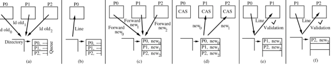
Figure 4.4 shows the operation of Caspar for three processors. In Fig-ure 4.4(a), all processors issue TLs, and get queued as P0 first, then P1, and
then P2. The queue contains no newvalues. In Figure 4.4(b), the directory
provides the line to P0, which is at the head of the queue. Soon after the
TLs reach the directory, the forwardednewvalues also arrive at the directory, and are stored in the queue (Figure 4.4(c)). The directory immediately sends
new0 1 new new2 P1, P0, P2, −− −− −− P0, P1, P2, new2 −− −− −− P0, P1, P2, new0 1 new new2 P1, P0, P2, new1 2 new P2, P1, ld old1 2 ld old ld old0 new 0 new1 new 0 new 2 new1 P0 P1 P2 (d) CAS CAS CAS (a) P2 P1 P0 (b) P2 P1 P0 (c) (e) P0 P1 Line Validation (f) P2, Line Validation P1 P2 Directory Queue P0 Line Forward Forward Forward
Figure 4.4: Operation of eager forwarding.
the new values to the successor processors, and all processors now have the data they need to perform the CAS in parallel (Figure 4.4(d)). As described before, the directory attempts to get the line from P0. When it succeeds
(Figure 4.4(e)), it pops the first entry from the queue and replies to the next entry’s TL by sending the line to P1. P1 validates the speculative execution
and commits it. The directory repeats the same process for P2, which is the
new head of the queue (Figure 4.4(f)).
4.3.2
Architectural components required
Eager forwarding requires architectural components to: (1) transfer the new
value to the successor, (2) accept an earlyold value from the predecessor and later validate it, and (3) support speculative execution from the TL until the execution is validated. We describe each one in turn and outline the hardware structures.
A. Transfer the new value. In a conventional pipeline, a CAS instruction performs the read-modify-write of a cache line when it is at the head of the Reorder Buffer (ROB). WithCaspar, a CAS instruction whose address hits in the Active CAS (AC) (Figure 4.1(b)) has a two-step execution. First, as soon as itsnewvalue is known, it forwardsnewto the directory. Second, when it reaches the ROB head and we know itsnewvalue and itsoldvalue (perhaps speculatively), it performs the read-modify-write as in a conventional system. Since forwarding the new value is on the critical path of the parallel exe-cution, it is performed as soon as newis known, bypassing all the other loads and stores by the processor. This is safe becausenewis observed only by the next processor in the directory queue (as it is deposited in the queue rather than in memory), where it is used only as a hint that is validated upon com-mitting (i.e., as a value prediction). As detailed in Section 4.3.4, standard
speculative execution conflict checks guarantee that using a forwarded value does not cause memory consistency errors.
B. Old value use and validation. After a processor issues a TL to mem-ory, it may receive a speculative oldvalue from the directory. Such a value is stored in the AC structure, and cannot be used until the TL has reached the ROB head and checkpointed. At that point, execution turns speculative, and the thread can use the received old value. In particular, the CAS operation may use it, and store the speculative CAS result in the cache.
Eventually, the processor will receive from the directory the line requested by the TL. Then, the hardware compares the value in the incoming line to the speculative old value. If the values are different, execution is rolled back to the checkpoint and the value in the line is used rather than the speculative old value. Otherwise, the work done so far is useful and correct, and is committed. Note that this value-based validation does not introduce an ABA problem [44]. Since the directory manages the hardware queue, a processor can only see updates from its immediate predecessor; no other processor’s updates can interleave between the two.
C. Speculative execution from TL to validation. When a TL reaches the ROB head and the requested line is not in Exclusive (or Dirty) state in the cache, the hardware performs a checkpoint and the processor enters speculative execution. If, instead, the line is already in one of these states, there is no need to become speculative because the CAS will execute with safe data very soon.
As in conventional TM, during speculative execution, data conflicts with incoming coherence transactions cause an abort. If speculative data is about to overflow the cache, the execution can stall rather than abort. There is no danger of deadlock because there is always a non-speculative thread—the one at the head of the queue.
At some point during speculative execution, the requested line is provided by the memory system. If the processor had used a speculative old value, then the hardware performs the above validation step, and the transaction commits or aborts. This may occur past the CAS execution.
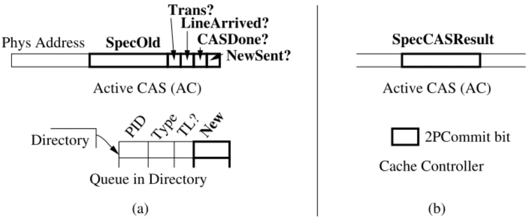
D. Hardware structures. Figure 4.5(a) shows the two main hardware structure extensions required for eager forwarding. First, in the processor, the Active CAS (AC) is extended to include the speculative old value re-ceived (SpecOld) and a set of bits (Trans?, LineArrived?, CASDone? and
NewSent?). The speculative old value is kept in the AC to compare it to the line’s value in the validation step. The bit fields are used by a state machine to track execution states.
Directory PID Type TL? New
Queue in Directory
2PCommit bit Cache Controller
Active CAS (AC) Phys Address Trans? LineArrived? CASDone? NewSent? SpecOld
Active CAS (AC)
(b) (a)
SpecCASResult
Figure 4.5: Additional hardware for eager forwarding (a) and parallel CAS validation (b).
In the directory queue, we add one extra field per entry. For the entry of a given processor, the field contains the newvalue forwarded by the processor to the directory.
4.3.3
Timeline
Figure 4.6 shows a typical timeline of eager forwarding. The events are shown above the horizontal line, while the actions are shown below the line.
(1) of ROB (2) Checkpoint New data computed (3) received Old data (4) CAS at head of ROB (5)
Execute CAS Validate and
Line arrives (6) Time as triggeringidentified Load T Issue T T at head
and start New data Use Old datain execution terminate
speculation speculation
Speculative execution Forward
Figure 4.6: Timeline to perform eager forwarding.
The first event occurs when a load is identified as TL (Section 4.1). Event (2) is when the TL reaches the ROB head. Unless the line is already in
Exclu-sive (or Dirty) state in the cache, the hardware checkpoints and starts spec-ulative execution. Event (3) occurs when a CAS instruction in the pipeline finds that its address matches the one in the AC, and that its register operand with the new value to write is already full. In this case, the hardware for-wards the newvalue to the directory. Typically, the CAS is not at the ROB head.
When an old value is received for a line with the CM bit set, it is saved in the SpecOld field of the AC for later validation. If the processor is in speculative mode, then Event (4) occurs, and the received old value is used in the execution.
Event (5) occurs when the CAS instruction reaches the ROB head, the register operands with its new value and itsold (possibly speculative) value are full, and all prior accesses have completed. The CAS then executes, either speculatively (reading from SpecOld) or not (reading from the cache). If the CAS succeeds, the cache is updated. Irrespective of whether the CAS succeeds, execution continues (possibly speculatively).
Finally, Event (6) occurs when the requested line finally arrives for a cache entry marked with the CM bit. The hardware validates the SpecOld field of the AC against the line. If the validation fails, the processor rolls back to the checkpoint; otherwise the speculative execution commits. In all cases, the AC and the CM bit get cleared.
These events may be ordered in slightly different manners. In all cases, it can be shown that the algorithm works.
A processor may forward a new value to the directory twice. This may occur in a branch misprediction wherenew is forwarded on both sides of the branch. The directory only takes the first forwarded value. This case may cause the successor processor to fail the validation. However, correctness is guaranteed.
4.3.4
Memory consistency issues in forwarding data
In Caspar, thenewvalue of a processor (Pi) finds its way to the immediate successor in the queue (Pi+1) before Pi performs the CAS. In addition, new can bypass all the other outgoing accesses from Pi. This operation causes no memory consistency errors for the following reasons.
First, the forwarded value does not update memory; it is saved in the directory queue and sent to Pi+1. Second, if new’s value is wrong, the worst
that can happen is that Pi+1 executes past the CAS, gets squashed when its
validation fails, and restarts from the TL using the correct value.
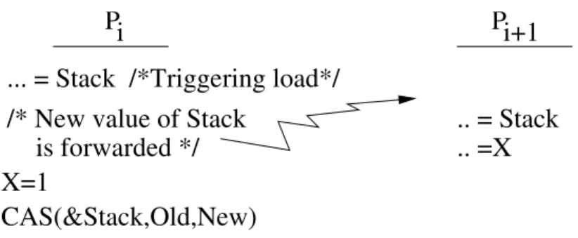
Sincenewcan bypass earlier accesses in Pi’s outgoing buffers, Pi+1may
ob-servenewbefore it observes other Pi accesses that precede the corresponding CAS in Pi’s program order. Figure 4.7 shows an example, where Pi performs a TL and CAS on locationStack. In between the two, thenewvalue ofStack
is forwarded before Pi updates variable X. It is possible that Pi+1 reads the
forwarded value of Stack and then X. Hence, it observes the new value of
Stack and the old value of X. This will not cause a consistency violation because Pi+1 turns speculative when it reads Stack. Hence, when Pi writes X, it will send an invalidation to Pi+1 and squash Pi+1’s execution.
Pi
Pi+1
.. = Stack
.. =X
... = Stack /*Triggering load*/
X=1
CAS(&Stack,Old,New)
/* New value of Stack
is forwarded */
Figure 4.7: Forwarding causes no consistency violation.
In fact, Pi+1’s transaction can commit only if it uses the correct state. The
transaction cannot commit until Pi performs the CAS, and Pi+1 receives the
line and validates thenewvalue that it used. By this time, all of Pi’s accesses that precede the CAS have been completed, including all writes. Such writes would have squashed Pi+1’s transaction if it had read an incorrect value.
Moreover, Pi cannot read any state generated by Pi+1 beforenewis validated
because Pi+1’s execution is speculative.
4.4
Parallel CAS Validation using Group Commits
With eager forwarding, the queued processors still perform the CAS valida-tion step sequentially (Figures 4.4(e)-(f)). In theory, this should not hurt
performance because processors do not stall after a CAS waiting for vali-dation: they continue executing speculatively. In practice, however, it is desirable to validate sooner for two reasons. The first one is to reduce the time a processor remains speculative and, hence, exposed to aborts. The second reason is to avoid stalls in codes where a processor repeatedly exe-cutes CASes to the same address—a common pattern in codes with fine-grain synchronization.
Indeed, assume that a processor has issued a TL and completed a CAS, but has not received the line yet. It remains speculative. Suppose that it then executes the load for a second load-to-CAS to the same address. Since the AC is still full, the load is not designated a TL but a plain load. The load goes to the cache and stalls, waiting for the line requested by the TL. The pipeline will likely stall soon after. In essence, the processor has overlapped as much speculative execution as it could with the TL, and it now stalls. It will not resume execution until the processor receives the line.
If we have a long queue, it will take on average a long time for the line to reach a processor. As a result, if a processor repeatedly executes CASes to the same address, it will likely stall for long periods.
To solve these two problems, we propose to accelerate the CAS validation by performing it in parallel.
4.4.1
Intuitive idea
We augment the design of Section 4.3 to validate the CASes in groups of queued processors at a time. The idea is to augment the protocol so that the directory orchestrates group commits in a manner modeled after the
two-phase commit (2PC) in transactional processing.
Consider a queue of processors, where many have forwarded their new
values to the directory—which in turn has saved the values and sent them to their successors. When the directory finally obtains the line, rather than sending it to the next processor in the queue for validation, it attempts to
group-validatea group of processors. To do this, as it dequeues the processor that supplied the line, it checks that the value that the processor forwarded in the past matches the current value in the line. If so, it proceeds to group-validate the next set of contiguous processors in the hardware queue that
have provided their newvalues. It does so in three steps.
First, it sends a Prep message (for “prepare-to-commit”) to all of these processors in parallel. In each message (say to processor Pi), the directory includes the newvalue that the processor had earlier forwarded to the direc-tory (newi). The goal is for Pi to validate it against the outcome of Pi’s CAS. Recall that newi has already been used by the successor processor Pi+1.
Second, when Pireceives thePrepmessage, it comparesPrep’s value (newi) to the result of its CAS. If the values match, the validation succeeds. Pi then responds to the directory with an Ack message and temporarily sets the pipeline in a quiescent, stalled state to enable a correct 2PC (see Sec-tion 4.4.2). If, instead, the values do not match, or Pi has not performed its CAS yet, or Pi has other pending accesses waiting for the same cache line, then Pi responds to the directory with a Nack message and does not stop execution.
Third, after the directory gets all the responses, it identifies the set of contiguous processors (starting from the head of the queue) that responded with Ack. To these, it sends aCommit message and removes them from the queue; they commit their speculative execution and then resume. To the others that sent Acks, the directory sends a Resume message; they resume executing speculatively. Finally, to the ones that sent Nacks, it does not respond.
If the first processor in the queue sent aNack, the group commit fails. We will see that this processor then falls back to the sequential CAS validation of Section 4.3.
CAS0 CAS1 CAS3 CAS0 CAS1 CAS3
new0 1 new new2 P2, new3 Directory P1, P0, P3, Queue new0 1 new new2 P2, new3 newPrep new0 1
Prep Prep new 3 Prep 2 new
CAS0 CAS1 CAS3 CAS0 CAS1 CAS3
new0 1 new new2 P2, new3 new2 3 new P2 P1 P0 P3 P2 P1 P0 P3 (a) (b) Directory P1, P0, P3, Ack Ack Ack Nack Commit Commit Resume P2 P1 P0 P3 P2 P1 P0 P3 Directory P1, P0, P3, Directory (c) (d) P2, P3,
Figure 4.8: Parallel CAS validation.
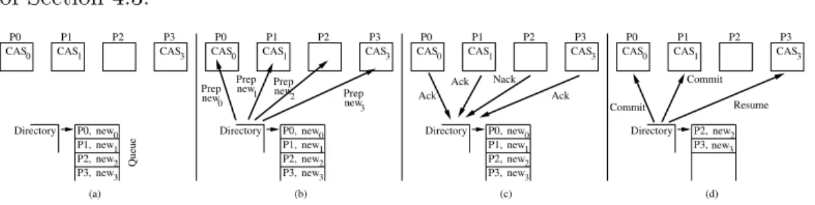
Figure 4.8 shows an example of parallel CAS validation. In Figure 4.8(a), four processors are queued up and have forwarded their new values to the directory (which has passed them to their successors). In addition, P0, P1,
has attained the line—hence, the line is not in any cache.
In Figure 4.8(b), the directory initiates a group commit. It sends a Prep
to the four processors, together with the corresponding new values that the processors had forwarded. On reception, processors P0, P1, and P3 compare
the new value to the outcome of their CAS. Assume that the values match. Hence, as shown in Figure 4.8(c), they send Acks to the directory. P2 has
not completed its CAS yet. Hence it sends a Nack. In Figure 4.8(d), the directory finds that, starting from P0, the set of contiguous processors that
responded with Ack consists of P0 and P1. So, these two can commit in a
group. The directory sends aCommitto them and removes their entries from the queue. It sends a Resume to P3.
4.4.2
Architectural components required
Parallel CAS validation requires components to: (1) quiesce a processor pipeline in a two-phase commit, (2) commit a load-to-CAS section with-out the processor ever obtaining the memory line with the CAS data, and (3) seamlessly revert to sequential CAS validation if group validation fails.
A. Quiesce a pipeline in a two-phase commit. We extend the Active CAS (AC) structure to save the result of a speculative CAS execution. Then, if the processor receives a Prep, it compares the message’s newvalue to the result of the CAS. If they are the same, the processor prepares for a two-phase commit (2PC).
For correctness, the 2PC requires that the processor be able to commit if it is instructed to do so. Thus, its speculative execution must never get squashed after sending an Ack. Quiescing the pipeline achieves this: The processor stops issuing new instructions and flushes the pipeline, discarding all the unretired instructions. It also sets a new bit in the cache controller called 2PCommit. This bit will reject all incoming coherence requests that could cause a squash of the thread—i.e., incoming reads to speculatively written lines, and incoming writes to speculatively accessed lines. Finally, when the write buffer is drained, the processor disables interrupts (like in the x86 CLI instruction), bringing the pipeline to the quiescent state.
Once in quiescent state, the processor sends the Ack to the directory. It remains quiescent until the arrival of a Commit or Resume. Then (after
committing the thread if the message was a Commit) the 2PCommit bit is cleared to accept all coherence requests. Interrupts are re-enabled (like in x86’s STI instruction) and the processor re-starts issuing instructions.
It is possible that a pipeline cannot get into a quiescent state because the writes in its write buffer end up getting rejected by another processor with its
2PCommit bit set. This case is detected because the response to the rejected writes indicates that the destination processor does not accept requests. In this case, the processor refuses to participate in the 2PC: it sends a Nackto the directory and continues executing. Its CAS will be validated later, either in a group or sequentially with the default algorithm.
B. Commit without ever getting the cache line. A successful parallel CAS validation is fast because the memory line with the CAS data does not need to be transferred between the caches of the processors involved. Instead, these processors commit their load-to-CAS code without ever obtaining the line in their caches.
To see how it works, consider a processor that is executing a load-to-CAS section. The TL caused a cache miss, which triggered the allocation of an MSHR entry and of space for a line in the cache. When the old value is re-ceived from the predecessor, it is stored in the MSHR and used speculatively. Later, the CAS is performed speculatively and its result is stored in the AC. Suppose that a Prep now arrives and its value matches the CAS value in the AC. If and when the Commitis eventually received, the hardware simply commits the execution. In addition, it discards the MSHR entry and frees up the empty cache line.
C. Seamlessly revert to sequential CAS validation. Whenever a group commit fails, our algorithm performs a sequential CAS validation like the al-gorithm of Section 4.3. Specifically, a failure occurs when the first processor in the queue (P0) responds to the directory’s Prep with a Nack. This may
be because either P0 has not performed its CAS yet or P0’s CAS fails the
validation—i.e., the CAS produces a value different from the one P0
for-warded to the directory (new0). In either case, in Caspar, the directory
sends the memory line to P0, which performs a local CAS validation as
de-scribed in Section 4.3. The directory also sends Resumes to processors that sentAcks. As usual, the directory will then try to obtain the cache line from P0. Once it gets it, it attempts the next parallel CAS validation.
structure extensions required. First, in the processor, the Active CAS (AC) is extended to include the result of the speculative CAS operation ( SpecCA-SResult). Second, in the cache controller, we have the2PCommit bit, which rejects incoming coherence requests that could cause a squash of the thread during the two-phase commit.
4.4.3
Timeline
Figure 4.9 shows a typical timeline for parallel CAS validation from a proces-sor’s point of view. In Event (1), the processor receives a Prep but, because it has not executed the CAS, it responds with a Nack and continues. In Event (2), it performs the CAS. In Event cluster (3), the processor receives a Prep and after validating the CAS, sends an Ack and stalls. However, it then receives a Resumebecause it is not in the set of committing processors, and resumes. CAS at head of ROB Prep Receive Send Nack Execute CAS (2) Send Ack Prep Receive Resume Receive Continue Prep Receive Send Ack Time Commit Receive arrives Line(5) (1) (3) (4) Commit speculation
Validate and commit speculation
Figure 4.9: Timeline of parallel CAS validation.
Moving forward, the speculative work is committed in one of two ways: either the processor commits in a group (upper line) or alone (lower line). In the former case, the processor receives a Prep, responds with an Ack and stalls, and then receives a Commit and commits the speculative work. In the latter case, the processor receives the line and compares its value to the SpecOld field of the AC. If they are the same, the speculative work is committed.
CHAPTER 5
EVALUATION
5.1
Experimental Setup
We evaluate Caspar with simulations of a 64-core chip using the Sniper simulator [52]. Table 5.1 shows the baseline architecture modeled. The core and L1/L2 cache parameters are taken from Nehalem [53]. We implement three designs which incrementally build on top of this baseline (B). They are Queue (Q), EagerForwarding (EF) andCaspar(C).Queueimplements basic hardware queueing in each module of the distributed L3 tag directory, similar to past proposals, as per Section 4.2. EagerForwarding adds parallel CAS execution with eager forwarding as per Section 4.3. Caspar further adds support for parallel CAS validation using group commits as per Section 4.4, and is our complete design.
Table 5.1: Architecture simulated.
Parameter Value
Architecture 64 cores on chip
Core 2.66 GHz, 4-wide out-of-order
ROB, Res. Stations 128 entries, 36 entries (unified)
Private L1 32KB WB, 8-way, 4 cycles round trip
Private L2 256KB WB, 8-way, 9 cycles round trip
Shared, NUCA L3 16MB WB, 16-way, 12 cycles (near access)
Cache line size 64B
Coherence MESI, full-mapped tag directory
Network 2-D torus, 2-cycle hop latency, 64 bits/cycle
link
Main memory 120 cycles round trip
Entering quiescence ≈Time to drain write buffer
We use two sets of programs for our evaluation (Table 5.2): five kernels and four applications. The kernels consist of four computational kernels (FIFO,LPO,MBrot, and LIFO) and one standard memory allocation kernel (Larson). In the computational kernels, each thread executes a loop where, in each iteration, the thread performs some computation and then synchronizes
with a lock-free operation. The memory allocation kernel runs Michael’s memory allocator [11], which internally uses lock-free algorithms.
Table 5.2: Programs evaluated.
Program Description
Kernels:
FIFO Add/remove from Michael and Scott’s lock-free queue [39].
LIFO-push-only (LPO)
Push into a lock-free stack, modeling bulk synchronization [48] or initial population of a work list.
MBrot Mandelbrot set computation. Computing threads pass results to rendering thread via a multi-producer/single-consumer queue.
Larson Threads allocate/deallocate objects, while transferring some objects to be freed by other threads [54].
LIFO Push/Pop into a Treiber’s lock-free stack [40].
Applications:
FFT 1D FFT of a vector of complex values from BOTS.
CC Connected components computation based on a concurrent union-find
algo-rithm from Galois. Input is USA road network.
IS Maximal independent set computation from Galois. Input is USA road
net-work.
DT Delaunay triangulation from a given a set of points from Galois. Input is 5
million 2D points.
The applications are FFT from the Barcelona OpenMP Tasks Suite (BOTS) [55] and three graph analytics programs from the Galois system [56, 4]. BOTS includes several task parallel applications from various domains; we evalu-ate FFT, which uses fine-grained tasks and stresses the task scheduler. We run FFT using the open-source Qthreads parallel runtime [57, 47], which supports multiple scheduling options. We compare schedulers that use lock-free LIFO [40] and FIFO [39] queues to the default lock-based scheduler. Galois [56] provides a domain-specific language and runtime for graph al-gorithms. The runtime parallelizes graph analytics loops using a work list data structure where threads add/remove work. We evaluate three Galois programs where work list synchronization accounts for a sizable fraction of the execution time. Galois supports several distributed topology-aware work list implementations [4] as different graph algorithms require different work list properties (e.g., LIFO vs. FIFO) for best performance [58]. We add lock-free LIFO and FIFO work lists to the Galois 2.2.1 runtime 1 and
com-pare the execution time to the default lock-based work list. For the baseline Galois system, we picked the best work list implementation for each bench-mark. We then compared the synchronization time in these programs to the synchronization time in the lock-free versions under Caspar.
5.2
Kernels
Since the threads in the kernels repeatedly perform work and then synchro-nize using a lock-free algorithm, we use CAS throughput—the number of successful CAS operations per unit time—as the performance metric. We measure throughput over 5 ms (13.3 million cycles) of kernel execution time. Figure 5.1 shows the results, normalized to the throughput of the baseline (B) design. On average, EF and C improve the CAS throughput by 53% and 83%, respectively, over the baseline multicore (B), and by 10% and 32%, respectively, over hardware queues only (Q).
FIFO
LPO
MBrot
Larson
LIFO
Avg.
0
1
2
3
Normalized
Throughput
Base(B)
Queue(Q)
EagerForwarding(EF)
CASPAR
(C)
Figure 5.1: Kernel throughput for the different designs.
The gains vary depending on the kernel characteristics. Hardware queueing (Q) provides benefits in most of the kernels. The benefits are especially large in Larson and LIFO, where B’s CASes frequently fail. Q eliminates CAS failures by enforcing load-to-CAS atomicity.
EF provides additional throughput boost for most kernels. The improve-ments are largest in the kernels with mostly enqueue operations, namelyLPO
and MBrot. The other kernels have both enqueue and dequeue operations; the latter have CAS dependencies as shown in Figure 3.1(c), which reduce the frequency of eager forwarding.
C improves over EF in all kernels except FIFO. To see why, recall that a processor in EF can execute speculatively past a CAS but stalls upon attempting to execute another load to the location that was CASed until the pending cache line arrives (Section 4.4). The wait time for the cache line is proportional to the length of the queue in the directory. On average,
the queue size increases by 2.2x from Q to EF, since speculative execution increases the rate at which a core issues TLs. This results in stall cycles for kernels where the work between successive executions of the load-to-CAS section is too small to absorb the wait time for the cache line. This is the case for all kernels under EF except FIFO. On the other hand, C uses group commit to dequeue groups of processors at a time. With C, the average queue size is ≈33% of Q’s. This reduces the stall and improves the throughput of C over EF in these kernels. In FIFO, EF had few stall cycles, and so C and EF perform comparably.
5.2.1
Impact of the amount of work
We now measure the change in throughput as we change the amount of work performed between synchronizations. We start with the amount of work in the experiments of Figure 5.1 and progressively reduce the work. Figures 5.2(a)-(c) show the throughput of LPO, MBrot and LIFOin each of the architectures. The plots are normalized to the B design for the amount of work in Figure 5.1. 2500 1500 500 2 4 6 Work cycles Normalized Throughput B Q EF C (a) LPO 1925 1450 1000 1 1.5 2 2.5 3 Work cycles Normalized Throughput B Q EF C (b) MBrot 2500 1500 500 1 1.5 2 2.5 Work cycles Normalized Throughput B Q EF C (c) LIFO 32 48 64 1 1.5 2 #Cores Normalized throughput B Q EF C (d) LPO 32 48 64 1 2 3 4 #Cores Normalized throughput B Q EF C (e) MBrot 32 48 64 0.5 1 1.5 2 #Cores Normalized throughput B Q EF C (f) LIFO
MBrot-hw MBrot-lw FIFO-hw FIFO-lw 0 20 40 60 80 100 120 hw:high-work lw:low-work C EF C EF C EF C EF 35,37 18,18 18,31 18,24
Normalized
Cycles
Non-speculative cycles Stalls in speculation QuiescentSpeculative cycles with
useful work
Figure 5.3: Cycle breakdown for EF and C. The numbers at the top of the bars are the CAS throughput.
Reducing the work should increase CAS throughput, but it also increases CAS contention. In B, it increases the CAS failure rate. This results in a largely flat or decreasing throughput, which is the number of successful
CASes per unit time. In Q, hardware queueing improves synchronization efficiency and eliminates CAS failures. Hence, decreasing work increases the CAS throughput in two of the three kernels.
In EF, the throughput is initially higher than in Q because processors per-form part of the work speculatively. However, the throughput gap between the two narrows as the available work to speculate on decreases. EF is unable to exploit the reduction in work to improve throughput in two kernels—the processors eventually stall. Finally, C keeps increasing its throughput as the amount of work decreases. This is due to C’s parallel validation, which eliminates EF’s stalls.
To better compare EF and C, Figure 5.3 breaks down the normalized ex-ecution cycles in EF and C as they run MBrot and FIFO. We show two variants per kernel: high work and low work between CASes. The cycles are broken down into non-speculative execution, processor stalls while specula-tive, quiescent pipeline (C only), and speculative execution of useful work. On top of the bars, we have the CAS throughput in successful CASes per 1,000 cycles.
Consider MBrot first. When the work is low, EF stalls frequently. C converts a good fraction of these cycles to non-speculative cycles using group
commit. While C suffers from some quiescent pipeline cycles, the result is a large improvement in throughput. When the work is high, EF has fewer stall cycles. In this case, C converts both the remaining stall cycles and a portion of speculative cycles into non-speculative. However, the CAS throughput is not as high because improvements come only from the elimination of the stall cycles.
Consider FIFO now. When the work is low, EF has stall cycles and C eliminates most of them, increasing the throughput. When the work is high, however, EF has few stall or speculative cycles. The hardware queue is short and contains both push and pop requests. As a result, C is unable to perform much parallel CAS validation, and does not reduce either type of cycles. As a result, as shown in Figure 5.1, the EF and C throughputs are similar.
5.2.2
Scalability
We now measure the throughput as we change the number of processors for a fixed amount of work (i.e., the intermediate work amount from Figures 5.2(a)-(c)). This is shown in Figures 5.2(d)-(f), which are normalized to B with 32 cores. We note that LPO and LIFOhave high CAS contention. Hence, they scale poorly in B because, with more cores, we have more CAS failures. Q and EF maintain performance for these kernels even at a high core count. C breaks the sequential validation in EF, and scales well. On the other hand, MBrothas low CAS contention. Hence, B’s throughput improves with additional cores due to parallelization. Q and EF scale better, and C scales linearly.
5.3
Applications
Figure 5.4 compares the execution time of the applications (both LIFO and FIFO variants) on different architectures. The B bar is now replaced by two bars: L is the original lock-based version, and LF is the lock-free one. Q, EF, and C use the latter. The time is normalized to L and broken down into the categories of Figure 5.3—though the Quiescent cycles are too few to see. The average bars are not broken down. The number above each program is the fraction of the program time that we simulate. In Galois, this is the
phase in which the work list is populated.
FFT-FIFO FFT-LIFO CC-FIFO CC-LIFO IS-FIFO IS-LIFO DT-FIFO DT-LIFO Avg. 0 0.2 0.4 0.6 0.8 1 1.2 1.4 L:LockBasedLF:LockFree Q:Queue EF:Eager Fwd. C:CASPAR C EF Q LF L C EF Q LF L C EF Q LF L C EF Q LF L C EF Q LF L C EF Q LF L C EF Q LF L C EF Q LF L C EF Q LF L 5% 5% 10% 10% 30% 30% 100% 100% Normalized Time Non-spec. cycles Stall cycles in spec. Spec. cycles withuseful work
Figure 5.4: Execution time of the applications.
By taking L and re-writing the synchronizations in a lock-free manner in LF, the execution time decreases by an average of only 4%—in fact, in some programs, the time goes up. As we go from LF to Q, the efficient queue-based synchronization reduces the execution time by 22% on average. Among the applications, CC and DT have the highest reductions. This is because they have the least work between successive calls to the load-to-CAS region and, as a result, suffered a high CAS failure rate. Going from Q to EF, we see that adding eager forwarding reduces the execution time by 12% on average. The reductions are substantial in IS, where there are long queues and data is forwarded effectively. The other programs have smaller gains in EF: in CC and DT, the processors forward data but soon stall as they re-reference the CAS location; in FFT, the hardware queue has as many requests for enqueue as for dequeue operations, hampering data forwarding. Finally, going from EF to C, we see that adding group commits reduces the execution time by 40% on average. The largest reductions occur in CC and
DT, where the processors were stalled, and group commit allows them to make progress. In the other programs, C helps processors commit sooner, transforming speculative cycles into non-speculative ones. However, this does not translate into lower execution time.
Overall, C is a very robust design. On average, it reduces the execution time of these sections of applications by 47% relative to Q, and 58% relative to LF. It makes these lock-free sections 2.5x faster on average than the original, lock-based versions (L).
CHAPTER 6
DESIGN EXTENSIONS
LL/SC.Some architectures provideload-linkedandstore-conditional(LL/SC) instructions [59] instead of CAS. An LL reads from a memory location, and a subsequent SC to that location stores a new value only if the location has not been written to by another processor since the LL; otherwise, the SC fails. A successful SC guarantees atomicity of the LL-to-SC instruc-tion sequence (without any ABA issues), allowing LL-to-SC sequences to replace load-to-CAS sequences in lock-free synchronization. Casparapplies straightforwardly to LL/SC by using SC failures to identify contended lo-cations, turning LLs to such locations into TLs, and eagerly pushing values to be SC’d as new values. This makes our parallel execution and validation techniques agnostic to the atomic instruction used.
TM. We believe Caspar can also be extended to TM, which is increas-ingly being used for lock-free synchronization [60]. In typical TM designs, programmer-defined transactions that execute read-modify-write (RMW) ac-cess sequences to shared variables (e.g., a queue head) will abort on conflict and be serialized. Such transactions can ben
![Figure 3.1 shows the C code of Treiber’s lock-free LIFO stack [40]. As shown in Figure 3.1(a), the stack is a linked list of nodes, each of which holds a value.](https://thumb-us.123doks.com/thumbv2/123dok_us/533787.2562943/15.918.155.751.491.1034/figure-shows-treiber-lifo-stack-shown-figure-linked.webp)