Full Length Article
Real time implementation of an ANFIS-based induction motor drive via
feedback linearization for performance enhancement
Rabi Narayan Mishra
⇑, Kanungo Barada Mohanty
Department of Electrical Engineering, National Institute of Technology Rourkela, India
a r t i c l e i n f o
Article history:Received 13 July 2016 Revised 31 August 2016 Accepted 19 September 2016 Available online 28 September 2016 Keywords:
ANFIS controller
Linearized induction motor Decoupling feedback linearization Stationary reference frame Fuzzy control
a b s t r a c t
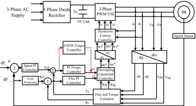
This research study displays a design of an adaptive neuro-fuzzy torque controller technique applied to induction motor drive via decoupling feedback linearization for enhancing the dynamic as well as the steady-state performance of induction motor drive. The decoupling controlled of induction motor is mod-eled by making the flux and torque decoupled, and simulation is carried out in the stationary reference frame with linearized controlled, based on state space linearization technique. As the induction motor are represented by significantly complex and time-varying dynamics like parameter variation, outer annoy-ance and load changes, an adapted control strategy taking into account Adaptive Neuro-Fuzzy Inference System (ANFIS) based controller is implemented which is a coordinated methodology and it yields ideal results by selecting appropriate rule base unlike fuzzy logic control procedure. The execution and effec-tiveness of proposed control technique based linearized induction motor drive is investigated in MATLAB environment in various operating conditions and the superiority of the proposed controller is analysed and is contrasted with the conventional PI controller based linearized induction motor. The system is also implemented on real time system using DSP 2812 to validate the different control strategies.
Ó2016 Karabuk University. Publishing services by Elsevier B.V. This is an open access article under the CC BY-NC-ND license (http://creativecommons.org/licenses/by-nc-nd/4.0/).
1. Introduction
Starting late the topic of nonlinear control is including a contin-uously key part in control system outlining and has transformed into an imperative bit of the control designing background [1]. Its promising usage in the motor drive control field is developing as a focus area for investigation. In many industries and automa-tion field frequently inducautoma-tion motors are utilized because of its ease, less cost, durability, suitability to work in an unusual domain, and essentially maintenance free. Despite that, it includes complex control approach as it has three unavoidable disadvantages as takes after. (a) It has nonlinear element with higher order mathe-matical equations, (b) No immediate estimation of flux and rotor current, (c) Parameters variation like rotor resistance and inductance.
Numerous effort has been made before to upgrade the perfor-mance and make the induction motor drive control strategy simple through field oriented control (FOC)[2,3]. This is a very popular method and has a significant impact on high-performance industry
applications by replacing costly, heavy DC motor drive. But FOC methods are very difficult to implement as the decoupling rela-tionship is obtained by proper state coordinates selection under the assumption of constant rotor flux, which leads to asymptoti-cally decoupling of rotor flux and torque. Furthermore, the decou-pling behaviour is not completely wiped off in the higher speed zone when the flux gets weakened[4]. This has led to nonlinear differential geometric control theory[6].
The differential geometric control approach proposed by Krezminski[7]is based on multi-scalar motor model where the rotor torque and flux are completely decoupled by static state feed-back controller by selecting new state variables which are different than that of FOC.
In the paper[8,10]it was demonstrated that multi-input sys-tems could get to be static feedback linearizable from input to state when an extra integrator is introduced to one of the inputs. This concept was taken care in[9]where an induction motor of fifth-order state-space model converts to a sixth-fifth-order model which is feedback linearizable. However, this controller structure had cer-tain demerits like 1) non-singular feedback linearizing transforma-tion is possible only if the torque produced by the motor is nonzero; 2) the control structure required switching between two distinct transformations to stay away from the singularities in the transformations. So to get over this, in[10]a single dynamic
http://dx.doi.org/10.1016/j.jestch.2016.09.014
2215-0986/Ó2016 Karabuk University. Publishing services by Elsevier B.V.
This is an open access article under the CC BY-NC-ND license (http://creativecommons.org/licenses/by-nc-nd/4.0/). ⇑Corresponding author.
E-mail addresses:[email protected](R.N. Mishra),kbmohanty@nitrkl. ac.in(K.B. Mohanty).
Peer review under responsibility of Karabuk University.
Contents lists available atScienceDirect
Engineering Science and Technology,
an International Journal
feedback linearization is proposed where the issue of singularity can be easily avoided. The main concept behind this is approaching of induction motor in the d-q coordinate system instead of a-b coordinates. Here one control quantity is transformed in two lin-earization schemes.
In [11], two nonlinear feedback control approaches are pro-posed for decoupling schemes of torque and flux control of current regulated induction motor. This is based on input–output lin-earization of the nonlinear system via dynamic state feedback con-trol. Further, in[12]the control performance of the drive system may degrade due to load perturbation, and detuning parameters which were evident from the sensitivity analysis.
The decoupling feedback linearized control strategies have suc-cessfully resolved the issue of coupling, leading fast transient response, but both are very much petulant to performance because of plant parameter variation, plant uncertainties, and external load disturbance, etc. Apart from that accurate estimation of flux is also required for perfect decoupling of rotor flux and torque.
In the most recent years, a significant amount of investigation works have been accounted for consolidating different control methods like classical PID controller [13] and contemporary control techniques like fuzzy logic[14–16], sliding mode controller [17,18,1], neural network controller [19]. Sliding mode control based feedback linearized induction motor drive has been proposed successfully in[20]. But this has the main drawback of chattering in control variables in a steady state which is again added with the chattering phenomena occurred naturally due to the presence of PWM switching in real-time hardware implementation.
Fuzzy logic controller[33,37]can handle the plant uncertainties and deviation of system parameter well, but it has the issue of instability, ambiguity, and optimal fuzzy logic control cannot be figured out by trial and error. Then again, it is greatly difficult to make a serial of training data for an artificial neural system that can deal with all the working modes[21,22]. Hence, some proce-dures have been developed to determine these troubles and streamline the job of tuning parameters and evolving rules for the controller that is improved and optimized[23,24]. The neural system idea taking into account of adaption technique is funda-mentally utilized for these ideas which are known as adaptive neuro-fuzzy control.
Adaptive Neuro-Fuzzy Inference System (ANFIS) based control is one of the late-developing control systems which overcome shortcomings of fuzzy logic and neural network and to construct a more effective intelligent system with enhanced configuration and performance features[24–26]. In a versatile neuro-fuzzy sys-tem, the neural network training technique is utilized to outline a fuzzy inference system[2,32,38].
This work proposes an intuitive feedback linearization con-troller (FBL) that conglomerates feedback linearization with ANFIS controller. The intuitive feedback linearization control which is dif-ferent than that of[27]is simple and thus simplifying the design-ing of the controller. The linearized model of induction motor formed by FBL technique is sensitive to parameter variations, plant uncertainties, which motivate to design a robust ANFIS control scheme for confronting these challenges in real world application of induction motor drive. The proposed ANFIS controller incorpo-rated with feedback linearized based induction motor drive for enhancing the performance is the novelty of this research work.
The mix of these strategies preserves quick and robust response of conventional PI-torque controller based linearized induction motor drive. Additionally, it remarkably reduces the torque ripple and improves the system dynamic as well as steady-state perfor-mance. The output of PI-flux controller, ANFIS controller, and d-q flux estimated from voltage model[2]are input to the decoupling linearized controller. The signal generated from decoupling
lin-earized controller is fed to hysteresis current controller[34]to pro-duce the required gate pulses for PWM voltage source inverter, which traces motor reference current to produce desired torque. This approach initially starts with the modelling of an induction motor in the d-q stationary reference frame.
2. Dynamic modelling of induction motor
The following equations characterize the dynamic mathemati-cal modelling of induction motor drive in the d-q stationary refer-ence frame. dids dt ¼ 1
r
Ls Rsþ L2m L2 r Rr ! idsþr
1 Ls LmRr L2 r wdrþ PLmr
LsLrx
rwqrþ Vdsr
Ls ð1Þ diqs dt ¼ 1r
Ls Rsþ L2 m L2r Rr ! iqsþr
1 Ls LmRr L2r wqr PLmr
LsLrx
rwdrþ Vqsr
Ls ð2Þ dwdr dt ¼ Rr LrwdrPx
rwqrþ LmRr Lr ids ð3Þ dwqr dt ¼ Rr LrwqrþPx
rwdrþ LmRr Lr iqs ð4Þ dx
r dt ¼ B Jx
rþ 1 JðTeTlÞ ð5Þ wherer
¼ 1L2 m LsLris the leakage coefficient, (ids,iqs), (Vds,Vqs), (
w
dr,w
qr) are the d-q component of the stator current, stator voltage and rotor flux respectively, (Rs,Rr) is the stator and rotor resistance and (Ls, Lr) are the stator and rotor inductance respectively.Lm,x
randP are the magnetizing inductance, rotor speed and number of pole pairs respectively.The expression of instantaneous electromagnetic torque pro-duced is given as
Te¼3
2
Lm
LrPðwdriqswqridsÞ ð6Þ
3. Decoupling feedback linearized control
Decoupling feedback linearized control is an approach to man-age nonlinear control strategy in which many investigations have been going on recent years. The prime thought about the strategy is to change over methodically nonlinear system dynamic mathe-matical equations into a totally or partially linear so that linear control technique can be applied. This contrasts absolutely from conventional linearization frameworks as this linearization is satis-fied universally, rather than neighbourhood of an equilibrium point[1]. The input–output feedback linearization is distinguished by specific state coordinate change. Thus, it uses a nonlinear change on system variables in another proper coordinate system that facilitates feedback introduction; therefore, another state lin-earization of new coordinate is developed. The theoretical approach and a deliberate methodology are given in[1].
The controller output parameter should be so chosen that the induction motor behaves like a DC motor making the rotor speed and flux decoupled. Therefore, output of control parameter to be chosen as
YT¼ ½
x
where,
x
randw
rare the rotor speed and flux respectively. Also, the total rotor flux in terms of d-q component of the rotor flux is expressed as w2 r ¼w 2 drþw 2 qr ð8Þ and dwr dt ¼ 1 wr wdr dwdr dt þwqr dwqr dt ð9Þ When the stator currents are directly controlled by a proposed linearized controller output,u^¼ ½u1^u2^T¼ ½idsiqsT , the Eqs.(3)–(5) are given by dwdr dt ¼ Rr Lrwdr
x
rwqrþ LmRr Lr u^1 ð10Þ dwqr dt ¼ Rr Lrwqrþx
rwdrþ LmRr Lr u^2 ð11Þ dx
r dt ¼ B Jx
rþ 1 J 3 2 Lm LrPðu^2wdru^1wqrÞ 1 JTl ð12Þ Now substitutingdwdr dt and dwqrdt from Eqs.(10) and (11)into Eq.(9) the linearized state space equations of rotor flux and speed are obtained as dwr dt ¼ Rr Lrwrþ LmRr Lr u1 ð13Þ d
x
r dt ¼ B Jx
rþ 1 J 3 2 Lm LrPu2 1 JTl ð14Þwhereu1 andu2 are considered as new control inputs that changes over coupled system into uncoupled one and is expressed as
u1¼w1 r
ðu^1wdrþu^2wqrÞ ð15Þ
u2¼ ðu^2wdru^1wqrÞ ð16Þ
Solving Eqs.(15) and (16), the nonlinear feedback controller which decouples the system is given byFig. 1(a).
The new inputsu1 andu2 are used as PI controller for better set point tracking of rotor flux and speed which are given by
u1¼Kp1ðwrwrÞ þKi1 Z t 0ð w rwrÞdt ð17Þ u2¼Kp2ð
x
rx
rÞ þKi2 Z t 0 ðx
rx
rÞdt ð18ÞThe Eqs.(13) and (14)define an electrical and mechanical system which has (ids⁄,iqs⁄) and (Wr,
x
r) as control input and output respec-tively. So it describes a framework that is coupled as the outputs and inputs are not directly related. Thus, the nonlinear control the-ory[1]is utilized to wipe out this coupled relation and makes the system inputsids,iqsand the outputsw
r,x
rtotally decoupled. The feedback decoupled system with Eqs.(13) and (17)is represented in the block diagram as shown inFig. 1(b). The accurate estimation of flux is required for perfect decoupling feedback linearization con-trol which is evident from Eqs.(15) and (16).4. Estimation of rotor flux
In order to design the proposed feedback linearization based induction motor drive, the rotor flux needs to be known accurately. When an induction motor of various speed ranges operate with precision control and better dynamic performance, the flux must be measured by installing a flux sensor. In contrast, the sensorless control without sensing the rotor flux has been evolving as indus-trial standards because of cost effective and reliability. As a result lot of research work has been going on over sensorless drive over past few decades[2].
An enhanced method of flux estimation has been proposed in [5]known as Luenberger observer, which is based on deterministic approach without the consideration of noise signal. Although the flux estimation accuracy is improved by the observer, there is a finite parameter variation effect. This estimation error tends to be more dominant as the sped approaches to zero. This led to an interest in stochastic approach based Extended Kalman filter. However, this observer based flux-sensorless drive [2] has the demerits of noise sensitive, modelling inaccuracies, and poor accu-racy at low speeds.
Therefore, to overcome the above issues, an estimation strategy is adapted based on voltage model[2], where the stator voltages and currents are sensed and the fluxes are estimated from the d-q stationary reference frame.
The d-q stator voltage and current components are calculated as follows. Vqs Vds ¼2 3 1 1 2 1 2 0 pffiffi3 2 ffiffi 3 p 2 " # Va Vb Vc 2 64 3 75 ð19Þ iqs ids ¼ 2 3 1 1 2 1 2 0 pffiffi3 2 ffiffi 3 p 2 " # ia ib ic 2 64 3 75 ð20Þ
where (Va,Vb,Vc) and (ia,ib,ic) are three-phase stator voltage and sta-tor current respectively.
From the d-q modelling of induction motor drive, the voltage equation in stationary reference frame can be stated as
Vds¼ ðRsþ
r
LspÞidsþLmLrp
W
dr ð21ÞVqs¼ ðRsþ
r
LspÞiqsþLmLrpW
qr ð22ÞFig. 1.Block diagram of (a) decoupling feedback linearized controller (b) closed-loop decoupled system.
The rotor torque and flux component can be obtained by using Eqs.(6), (21) and (22)which is shown inFig. 2.
The linearized model of induction motor formed by feedback linearization technique is sensitive to parameter variations, plant uncertainties. As a result, a robust ANFIS control scheme is designed for confronting these challenges in real-time application of induction motor drive.
5. Design of ANFIS-torque controller
The information representation of fuzzy logic consolidating with learning power of artificial neural network system gives Adaptive Neuro-Fuzzy Inference System (ANFIS). Subsequent to ANFIS plan starts with a prestructured framework, level of flexibil-ity for learning is inhibited that is the input and output member-ship function comprises of more information that a neural system needs to get from test pair of information. Data concerning a system under arrangement can be used right from starting. Some part of the system can be banished from training; therefore process is more effective. The intermediate results can be examined effort-lessly as the guidelines are in linguistic form structure. ANFIS implements a first order Sugeno fuzzy system as a result of its computational efficiency and versatile procedures[2,29]. To start ANFIS adjusting, a training data pair first that contains required input–output information set of the target system to be outlined is required. The objective is picked taking into account the best response of the system.
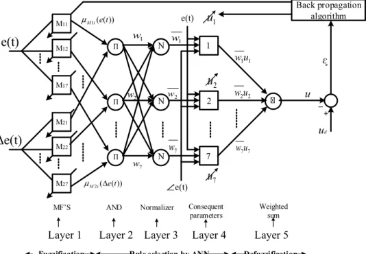
The schematic diagram of proposed ANFIS-based drive is demonstrated inFig. 3. The ANFIS controller structural design inte-grates fuzzy logic and learning algorithm with a five level artificial neural network arrangement [30] as portrayed in Fig. 4(a). The parameter of the fourth layer is modified by tuning to control any deviation of control effort. The two inputs of the ANFIS con-troller are given by
error;eðtÞ ¼TeTe
change in error;
D
eðtÞ ¼eðtÞkeðtÞk1T 100
whereTe⁄is the reference torque,Tis the sampling time andkis the sampling instant.
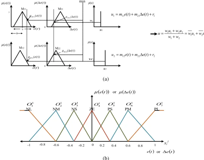
In the proposed Sugeno fuzzy model[2]depicted inFig. 5(a), the typical rule set with fuzzy rules can be expressed as:
Rule i (i= 1,2..7): if e(t) is M1i AND De(t) is M2i then ui¼m1ieðtÞ þm2iDeðtÞ þriwhere M1i and M2iare the antecedent fuzzy sets andm1i, m2iandriare the design parameters evaluated in training. Hereuiis the output singleton membership functions as shown inFig. 5(a).
Layer 1: Every adaptive node in this fuzzification layer contains node membership function.
O1i ¼
l
M1iðeðtÞÞ; i¼1;2;. . .7 ð23ÞO1i ¼
l
M2iðD
eðtÞÞ; i¼1;2;. . .7 ð24Þwhere
l
M1iandl
M2iare chosen to be a linear triangular symmetri-cal membership function as shown inFig. 5(b) known as activation function which is specified by parameter {a,b} shown inFig. 5(a) as follows. O1 i ¼ 0; x1 i 6ab2 12jx1 iaj b ; a b 2<x 1 i <aþb2 0; x1 i Paþ b 2 8 > > < > > : ð 25Þ HereOiis the output corresponding to the node number, and superscript denotes the number of layers.xi1is the input corre-sponding to the node number of the first layer.Fig. 2.Block diagram of rotor flux and torque estimator.
Layer 2: In this layer, the minimum error or change in error value of two input weights are picked up as firing strength of rules by the product operator ‘AND’ which is symbolized byQ. O2
i ¼wi¼
l
M1iðeðtÞÞ:l
M2iðD
eðtÞÞ¼minð
l
M1iðeðtÞÞ;l
M2iðD
eðtÞÞ; i¼1;2. . .7 ð26ÞLayer 3: This layer is symbolized by N where the weight is cal-culated by every node. As there areinumber of weights in terms of firing strength of the rules, the normalized value with firing strength ofwican be represented as
O3 i ¼wi¼ wi X i wi; i¼1;2. . .7 ð27Þ
Layer 4: Every adaptive node i in this defuzzification layer determines the consequent valueuiand the output of this layer comprises of a linear function given by
O4
i ¼wiui¼wiðm1ieðtÞ þm2i
D
eðtÞ þriÞ; i¼1;2. . .7 ð28Þ wherewiis the output of layer 3, and (m1i, m2i,ri) is the parameter set which is reflected to be the consequent parameters of the linear output function.Layer 5: This is the output layer of ANFIS where the outputuis estimated by center-of-gravity method as specified below.
O5 i ¼ X i wiui X i wi ¼ X i wiui; i¼1;2;. . .7 ð29Þ
Back propagation
algorithm
M11 M12 M17 M21 M22 M27 MF’S AND Normalizere(t)
∆e(t)
N
N
N
1
2
7
e(t)
Δ
e(t)
Layer 1
Layer 2 Layer 3
Layer 4
Layer 5
Consequent parameters Weighted sum
ᶓ
u
u
dFuzzification Rule selection by ANN Defuzzification
1
w
2 w 7w
1w
2w
7w
1 1u
w
2 2u
w
7 7u
w
1u
2u
7u
+
_
)) ( ( 1i et M μ )) ( ( 2i et M Δ μ ∏ ∏ ∏(a)
(b)
The outputuofFig. 4which gives the predicted ANFIS value u1 ofFig. 3can be written as
u1¼u¼
X i
ðwieðtÞÞm1iþ ðwi
D
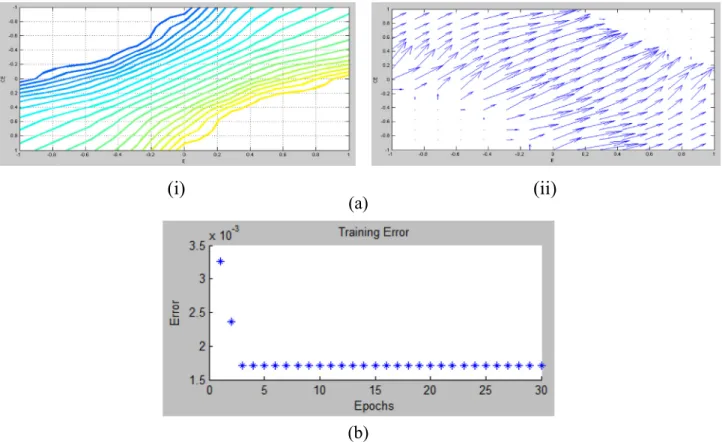
eðtÞÞm2iþ ðwiÞriÞ; i¼1;2;.. .7 ð30Þ Fig. 6(a) signifies contour plot and phase plot (vector plot) of error and change in error of the proposed controller, which ensures the stability of the system controller. In order to update the mem-bership functions parameter and weights, the ANFIS controller needs to be trained.6. Training algorithm for ANFIS controller
Backpropagation algorithm is used as a part of proposed ANFIS controller which is automatically tuned by least square estimation strategy[29]. Backpropagation algorithm is very fast where the weight is updated by gradient descent rule which has salient fea-tures like locating global minimum of cost function, fast conver-gence, good generalization and less computational complexity [35,36].
The cost function of proposed work while training ANFIS is defined as E¼1 2 Xn p¼1 ðud pupÞ 2 ð31Þ whereud
pstands for desired output forpth specific pattern andupis the actual output predicted by ANFIS.nis the number of training example which is 252 for this proposed controller. According to the network errornthe data is trained by backpropagation training algorithm.
Rather than employing the desired controller outputuas a tar-get, an error signalewhich studies the performance of the con-troller and assesses the present condition of system is utilized to manage the control activity into changing in right directions and in addition deliver the desired response[31]. So the objective func-tion to be minimized is redefined as follows.
E¼1 2ðT eTeÞ 2 ¼1 2e 2 ð32Þ
whereTe⁄is the reference torque andTeis the actual or estimated torque. To achieve the desired control performance, the backpropa-gation parameter adaptation rule for instantaneous parameter update can be derived as
aiðkþ1Þ ¼aiðkÞ
g
air
aiEðkÞ ð33Þbiðkþ1Þ ¼biðkÞ
g
bir
biEðkÞ ð34Þwiðkþ1Þ ¼wiðkÞ
g
wir
wiEðkÞ ð35Þwhere (ai,bi) is the value of (a,b) corresponding to ith node,
ð
g
ai;g
bi;g
wiÞis the fixed learning rate of corresponding parameters1 )) ( (et μ μ(Δe(t)) )) ( (et μ μ(Δe(t)) ) (t e Δe(t) ) (t e Δe(t) ) (u μ ) (u μ 0 0 u1 u2 1 w M11 M21 M12 M22 )) ( ( 11et M μ )) ( ( 12et M μ )) ( ( 2 1 et M Δ μ )) ( ( 2 2 et M Δ μ min 1 21 11 1
m
e
(
t
)
m
e
(
t
)
r
u
=
+
Δ
+
2 22 12 2m
e
(
t
)
m
e
(
t
)
r
u
=
+
Δ
+
2 2 1 1 2 1 2 2 1 1u
w
u
w
w
w
u
w
u
w
u
=
+
+
+
=
2 w a b NL NM NS ZE PS PM PL 0 -0.4 0.6 1 -0.6 -1( )
(
e t)
μ
orμ
(
Δe( )
t)
( )
t e or Δe( )
t -0.8 -0.2 0.2 0.4 0.8x
i1 1 2O
1 1O
O31 O14 1 5 O 1 6 O 1 7 O(a)
(b)
(ai,bi,wi) andðrai;rbi;rwiÞis the gradient of cost functionE corre-sponding to parameters (ai,bi,wi) which is described by the follow-ing equations.
r
aiE¼@@Ee@@Tee @@Teu @u @O1 i @O1i @ai ð36Þr
biE¼@@E e @e @Te @Te @u @u @O1i @O1 i @bi ð37Þr
wiE¼@@E e @e @Te @Te @u @u @wi ð38Þ(a)
(b)
Fig. 7.Membership functions of error (E) and change in error (CE) (a) Before training (b) After training.
)
i
i
(
)
i
(
(a)
(b)
The common differential terms of aforesaid equations are deter-mined as follows: @E @e¼T eTe ð39Þ @e @Te¼ 1 ð40Þ @Te @u ¼constantK ð41Þ
The value ofKis greater than zero for the proposed induction motor drive scheme [22,28]. The other terms of Eqs. (36)–(38) are determined from Eqs.(25)–(30)as
@u @O1i ¼PuiðkÞ wiðkÞ ð42Þ @O1i @ai ¼ 2 biðkÞ ð43Þ @O1 i @bi ¼ 1O1 iðkÞ biðkÞ ð44Þ @u @wi¼ uiðkÞ P o2 iðkÞ ð45Þ Error tolerance is used to create stopping criterion which is related to error size. The training will stop after the training data
error remains within this tolerance as shown in Fig. 6(b). These errors were displayed by taking 30 epochs for training which is sig-nificantly less as compared to artificial neural network training. The membership functions designed by parameter {a,b} is updated according to the error propagated in backward manner and thus changing the shape of the triangular membership functions. So after training, the error tolerance is closed to zero as shown in Fig. 6(b) and the shape of the membership functions are also altered. The membership functions before training and by using grid method, the membership functions after training are shown inFig. 7(a and b).
7. Experimental set-up
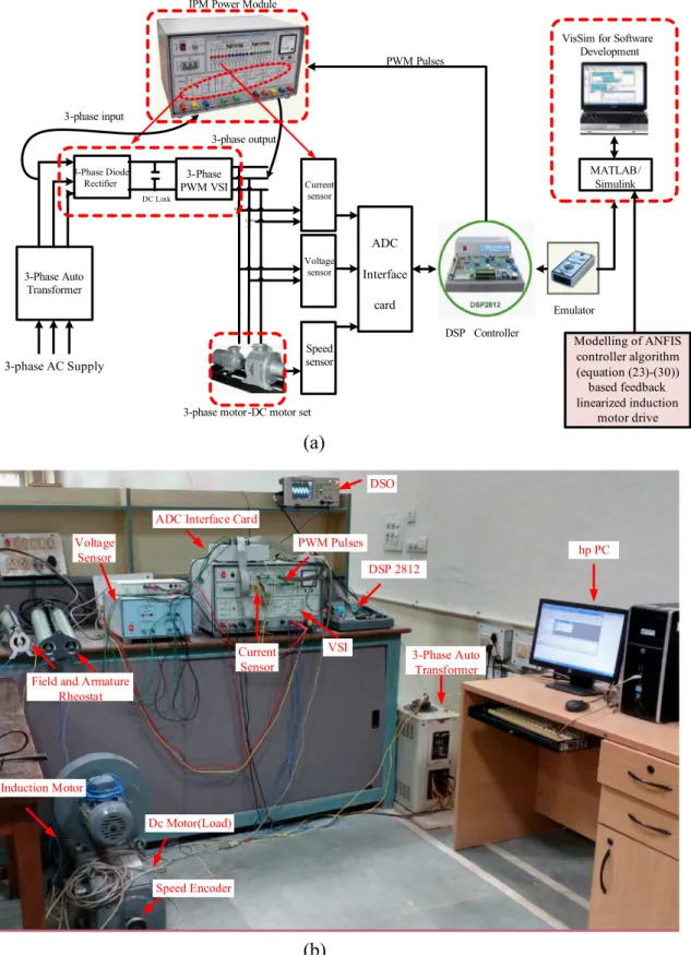
The proposed auto-tuned ANFIS based linearized controlled induction motor drive system was validated in real-time using the platform of 32-bit floating point DSP TMS320F2812. The proto-type real-time and experimental set up are illustrated inFig. 10(a and b) respectively. The motor specifications are same as given in Appendix A. Hall-effect voltage sensor and current sensor (LEM LTS 25-NP) sense the actual motor line voltages and currents respectively which are fed to DSP board through A/D channel. The rotor speed is sensed by speed encoder. The hysteresis current con-trolled PWM signals are generated by DSP board which are required to be fed to the switches of 3-phase voltage source inver-ter. In order to get the load perturbation for torque analysis, an induction motor is coupled to DC motor shaft. Then by introducing resistance on its armature circuit, load shaft is varied. Other than
0 0.4 0.6 0 200 400 400 0 0 0.4 0.6 Sp e e d ( rp m ) Sp e e d ( rp m ) 0 0.39 0.6 0 400 0 0.4 0.6 0 10 20 To rq u e (N-m) To rq u e (N-m) 0 0.39 0.6 0 10 20 0 0.4 0.6 -20 0 20 ia b c ( A ) 0 0.39 0.6 -18 0 18 0 0.4 0.6 0.5 0.6 0.7 Time (s) Fl u x ( W b ) 0 0.39 0.6 0.5 0.6 0.7 Time (s)
)
i
i
(
)
i
(
0 0.4 0.6 0 10 20 Time (s)(iii)
(a)
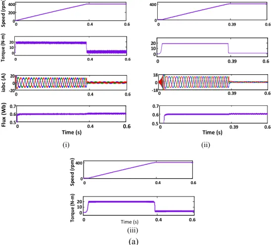
Fig. 8.Dynamic and steady-state performance characteristics (speed, motor torque, 3-phase stator current (iabc)) of Linearized decoupling controlled drive scheme during (a) Starting, (i) PI-torque controller, (ii) ANFIS-torque controller, (iii) Fuzzy logic torque controller, (b) Load perturbation (10N-m), (i) PI-torque controller, (ii) ANFIS-torque controller, (iii) Fuzzy logic torque controller, (c) Speed reversal, (i) PI-torque controller, (ii) ANFIS-torque controller, (iii) Fuzzy logic torque controler.
current, all the variables of this test are observed through D/A con-verter and are displayed on digital oscilloscope.
8. Results and analysis
8.1. Simulation results
The effectiveness and feasibility of proposed linearized concept with PI-torque controller and ANFIS torque controller are verified by MATLAB/Simulink environment using hysteresis PWM inverter with the sampling time of 2
l
s for 3.7 kw induction motor. The performance results corresponding to various responses of speed, torque, rotor flux, stator current are presented inFig. 8and a com-parative analysis is demonstrated inTable 1.8.1.1. Results with PI-torque controller
Case1: Starting dynamics and forward motoring: This illustrates that motor accelerates at a constant rate and reaches its set point speed of 400 rpm in 0.4 s with applied DC-link voltage of 646V as shown inFig. 8a(i). The current, torque and speed of induction motor are settled at 0.4 s, and the flux is almost uniform from starting to steady state. However, the sudden increase in capacitor voltage Vc is observed at starting as the capacitor charges and settles down later within 5–6 cycles by discharging through properly selected switching path as in
Fig. 9(i). Also, the capacitor voltage is reduced during the sud-den increase of stator current at 3 s as the energy stored in the capacitor gets released when the large current is drawn by motor through the capacitor and comes to the steady state after one cycle (0.02 s). Substantial ripple and chattering in tor-que are appeared in the tortor-que response with this PI controller. Case2: Dynamics of load perturbation:A sudden load torque of 10N-m is applied from 1 s to 1.5 s while the motor operating at steady state of 400 rpm as depicted inFig. 8b(i). It leads to undershoot and overshoot in speed of about 1.7 rpm at 1 s and 1.5 s respectively with settling period of around 10–11 cycles (0.2 s), accompanied by increase in stator current to 8.5 A and sudden decrease of capacitor voltage to 644 V settled at 1.02 s. Likewise, the capacitor starts discharging and charging during application and removal of the load, which is evident fromFig. 9(i). However, all through the operations, the flux is maintained uniform.
Case3: Dynamics of speed reversal and reverse motoring: Subse-quently, speed reversal is taking place at 2 s, deaccelerates at a uniform rate to zero speed and then settled at400 rpm at 2.73 s as shown inFig. 8c(i). This is accompanied by large stator current due to large negative motor torque and reversal of cur-rent takes place when speed crosses zero. During reversing, the frequency of the current is getting reduced first by the con-troller displaying regenerative breaking followed by phase reversal for getting the motor reversed. Again the motor
0.6 1 1.2 1.5 1.7 1.8 398.3 400 401.7 1.8 1.59 1.5 1.09 1 0.6 0.6 Times (s) 1 1.5 1.8 0 10 20 398.4 400 401.6
Sp
e
e
d
(
rp
m
)
Sp
e
e
d
(
rp
m
)
0.6 1 1.07 1.5 1.57 1.8 398.6 400 401.4 0.6 1 1.5 1.8 0 10 20To
rq
u
e (N-m)
To
rq
u
e (N-m)
0.6 1 1.5 1.8 0 10 20 0.6 1 1.5 1.8 -8.5 0 8.5ia
b
c
(
A
)
0.6 1 1.5 1.8 -8 0 8 0.6 1 1.5 1.8 0.5 0.6 0.7Time (s)
Fl
u
x
(
W
b
)
0.6 1 1.5 1.8 0.5 0.6 0.7Time (s)
)
i
i
(
)
i
(
(iii)
(b)
Fig. 8(continued)operates in the forward direction at 3 s and the speed, torque and currents are steady at 4.4 s. Furthermore, the responses demonstrate the replica of the previous one.
8.1.2. Results with ANFIS-torque controller
Operating conditions similar to PI-torque controller was carried out for starting, loading, and speed reversing as shown inFig. 8a(ii), b(ii), c(ii), and9(ii). At starting the current drawn by stator is less, i.e., 18A, settles rapidly at 0.39 s with less peak capacitor voltage Vc and less flux ripple as compared to PI-torque controller. The torque response during starting is significantly improved as the torque ripple is remarkably reduced. Further during reversing the speed in both forward and reverse direction, the motor settles down fas-ter at 2.7 s and 4.33 s. Moreover, this controller based linearized induction motor has less dip in capacitor voltage with less flux and torque distortion. During load perturbation at the same instant of PI-torque controller based linearized induction motor, it was observed that the use of ANFIS-torque controller improves the speed response by a good load disturbance rejection with less undershoot and overshoot of 1.4 rpm, less settling time of around 3–4 cycles (0.07 s) as compared to PI-torque controller. It has also remarkably less ripple than that of PI-torque controller. The torque ripple is substantially reduced as compared to PI controller leading to less distorted motor current. Also, it is evident from the result of Fig. 9(ii) that the proposed ANFIS controller does not deteriorate
the system performance considerably as far as the decoupling at all level is achieved; rather it demonstrates overall superior dynamic and steady state performance as compared to the conven-tional PI-torque controller and fuzzy logic torque controller.
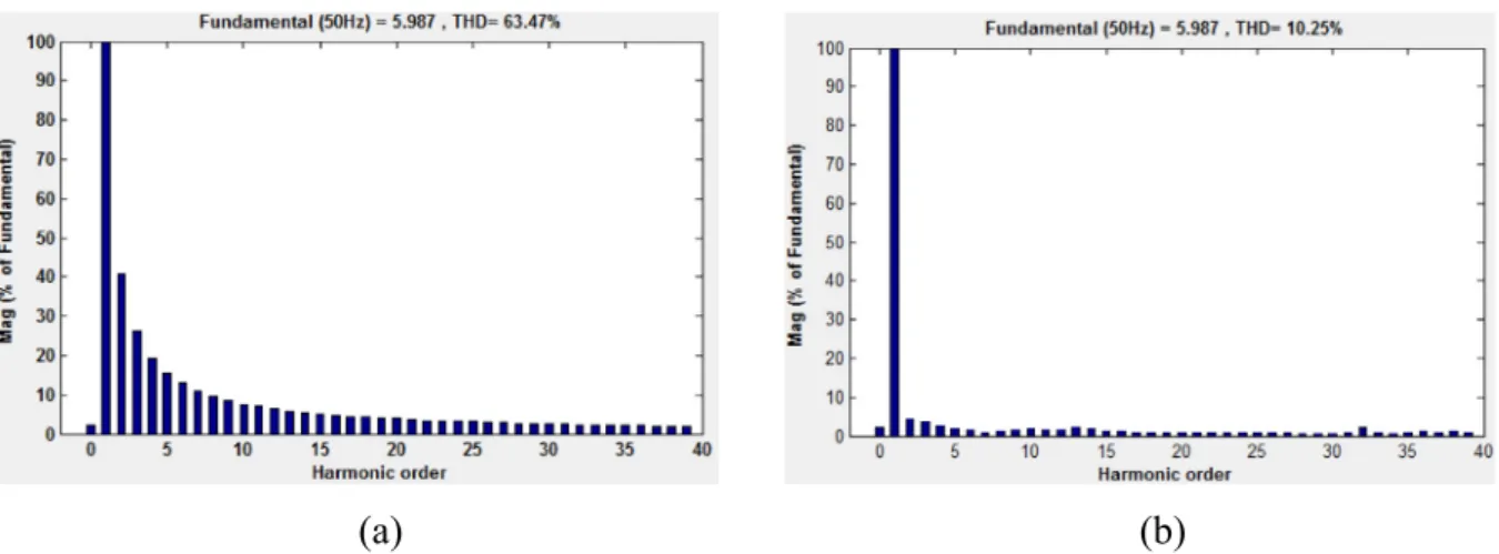
As the induction motor is highly nonlinear dynamics, the issues of power quality is the biggest challenge in real-time application, which is another aspect of research area of induction motor drive. However, in ANFIS-based drive, the power quality in terms of total harmonic distortion (THD) for stator current under the load of 10N-m is found to be 10.25%, which is lower as compared to PI-based drive having THD of 63.47%. These results are evident from Fig. 10. The reason of less THD in ANFIS-based drive is due to the fact that the optimum selection of rules by learning method of arti-ficial neural network. Also, the ANFIS based drive has the signifi-cant advantage of controlling pulse signal, which is independent of sampling time. This leads to have improved firing strength of the inverter and better power quality of induction motor drive.
8.2. Experimental validation
With the real-time experimental set-up shown inFig. 11, the linearized induction motor drive with PI and ANFIS torque con-troller are verified under various operating mode. Subsequently, in order to show the robustness of the controllers, the linearized induction motor drive is investigated with the different value of
1.8 2 2.73 3 4.4 5 -4000 400 1000 -400 1.8 0 -20 1.8 2 2.71 3 4.35 4.35 5 20 2 2.71 3 4.35 5 0 400 1000
Sp
e
e
d
(
rp
m
)
4.6 4.7 1000.08 1000.15 1.8 2 2.7 3 4.33 5 -400 0 400 1000 4.6 4.7 1000.14 1000.15 1.8 2 2.73 3 4.4 5 -20 0 20To
rq
u
e
(N-m)
4.61 4.7 6 1.8 2 2.7 3 4.33 5 -20 0 20 4.6 4.7 1 6 1.8 2 2.73 3 4.4 5 -20 0 20ia
bc
(
A
)
4.61 4.63 -4 0 4 1.8 2 2.7 3 4.33 5 -18 0 18 4.61 4.63 -4 0 4 1.8 2 2.73 3 4.4 5 0.5 0.6 0.7 Time (s)Fl
u
x
(
W
b)
4.61 4.62 0.595 0.61 1.8 2 2.7 3 4.33 5 0.5 0.6 0.7 4.61 4.62 0.595 0.61 Time (s))
i
i
(
)
i
(
(iii)
(c)
1000.15 1000.14 4.6 4.7 6 1 4.6 4.7 Fig. 8(continued)speed-PI controller under the step load of 5N-m as shown inFig. 15 in steady state speed by varying the armature resistance of DC motor connected to induction motor. The details of the experimen-tal performance under various operating conditions are mentioned inTable 1.
Case1: Initially, the experimental performance of starting dynamics and forward motoring is carried out under 400 rpm
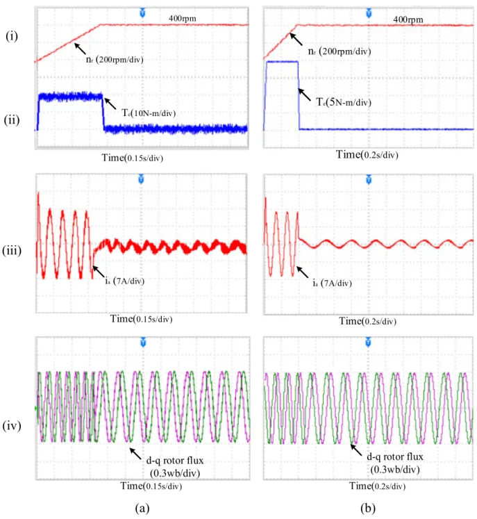
without any load perturbation as illustrated in Fig. 12(a and b). The linearized induction motor accelerates from rest condi-tion to steady state speed 400 rpm in 0.51 s using PI-torque controller, whereas it settles rapidly at 0.4 s using an ANFIS-torque controller. Also, the ANFIS-torque ripple is remarkably reduced to 0.34N-m using ANFIS-torque controller, which improves the torque response significantly as compared to PI-torque con-troller where the ripple is found to be 5.5N-m as shown in
Table 1
Comparative analysis of performance for different controllers.
Controller Speed (rpm) Torque ripples (N-m) Integral Time Absolute Error under load Settling time (s) Different time instants (s) Simulation Experiment Ripples % Undershoot and
Overshoot during load of 10N-m from 1 s to 1.5 s
Simulation Experiment ts(nr) ts(Te) ts(i) ts(nr) ts(Te) ts(i)
Simulation Experiment PI-Torque Controller 0.07 1.7 1.8 5 5.5 1.7 0 0.4 0.4 0.4 0.51 0.57 0.57 1 1.2 1.01 1.01 1.25 1.02 1.02 1.5 1.7 1.51 1.51 1.75 1.52 1.52 2 2.73 2.73 2.73 2.8 2.9 2.9 3 4.4 4.4 4.4 4.6 4.7 4.7 ANFIS-Torque Controller 0.002 1.4 1.6 0.3 0.34 0.8 0 0.39 0.39 0.39 0.4 0.44 0.44 1 1.07 1 1 1.1 1.02 1.02 1.5 1.57 1.5 1.5 1.6 1.52 1.52 2 2.7 2.7 2.7 2.6 2.7 2.7 3 4.33 4.33 4.33 4 4.1 4.1
)
b
(
)
a
(
Fig. 10.The THD performance of linearized induction motor drive for stator current under the load of 10N-m (a) PI-torque controller, (b) ANFIS-torque controller.
0 0.4 1 1.5 2 2.73 3 4.4 5 -1 -0.6 0 0.6 1 Ro to r d-q fl u x ( W b ) 4.61 4.66 0 0.39 1 1.5 2 2.7 3 4.33 5 -1 -0.6 0 0.6 1 4.61 4.66 0 0.4 1 1.5 2 2.73 3 4.4 5 600 646 750 Time (s) d c-li n k v o lt a g e ,V c (V ) 4.61 4.62 645 645.5 0 0.39 1 1.5 2 2.7 3 4.33 5 600 646 742 4.61 4.62 645 645.5 Time (s)
)
i
i
(
)
i
(
Fig. 9.Dynamic and steady-state performance characteristics (rotor d-q flux, dc-link or capacitor voltage, Vc) of Linearized decoupling controlled drive scheme during (a) Starting, loading (10N-m), and speed reversing, (i) PI-torque controller, (ii) ANFIS-torque controller.
Fig. 12(ii). The stator current response using both controllers is shown inFig. 12(iii). The starting current is 21A using PI-torque controller and using ANFIS controller; it is 19.2A along with less distorted and less magnitude steady state current. However, the rotor d-q components of flux are observed as a constant
magni-tude of ±0.6 Wb from starting to steady state without losing its decoupling behaviour which is evident fromFig. 12(iv). Case2: While induction motor operating in steady-state of 400 rpm, sudden load 10N-m is applied and taken out at instants 1 s and 1.5 s respectively as shown inFig. 13(a). This
3-Phase PWM VSI 3-Phase Diode Rectifier DC Link Current sensor Voltage sensor Speed sensor ADC Interface card IPM Power Module
DSP Controller
Emulator PWM Pulses
3-phase motor-DC motor set
MATLAB/ Simulink VisSim for Software
Development 3-phase AC Supply 3-phase output 3-Phase Auto Transformer 3-phase input Modelling of ANFIS controller algorithm (equation (23)-(30)) based feedback linearized induction motor drive hp PC DSP 2812 3-Phase Auto Transformer Dc Motor(Load) Induction Motor Speed Encoder DSO VSI PWM Pulses ADC Interface Card
Current Sensor Voltage
Sensor
Field and Armature Rheostat
(a)
(b)
leads to a speed undershoot and overshoot of 1.8 rpm at the instants mentioned above and settles down at 1.25 s and 1.75 s, respectively using PI-torque controller. The load pertur-bation makes the motor current to increase to 9.8 A at 1.01 s and decrease down at 1.51 s.
The responses with the ANFIS-torque controller though look similar to PI-torque controller based drive, there is a remarkable improvement of torque ripple, and better improvement of speed undershoot/overshoot by around 94% and 10% respec-tively over PI-torque controller based drive during load pertur-bation which is shown inFig. 13b(i) and (ii). Apart from this, the settling times of speed during load are 1.1 s and 1.6 s for instants 1 and 1.5 s which are increased by around 12% over
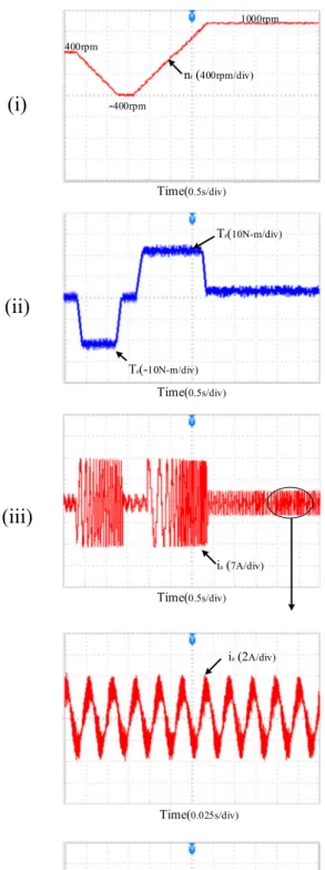
PI-torque controller. Nevertheless, the flux components for both types of controllers remain constant throughout the operation. Case3:Subsequently, the experimental performance in reversal mode of induction motor was observed inFig. 14(a and b). It takes place at 2 s with uniform deceleration reaching steady state of -400 rpm at 2.8 s and 2.6 s using PI and ANFIS torque controller respectively as shown inFig. 14(i). Further, the rotor gets back to forward mode at 3 s and settles 1000 rpm at 4.6 s and 4 s using PI and ANFIS torque controller respectively. Fig. 14(ii and iii) also reveal that the distortion of current and ripple contents in torque are drastically reduced by using ANFIS-torque controller. The rotor flux components shown in Fig. 14(iv) is observed as constant throughout the operations.
(i)
n
r(
200rpm/div)T
e(
10N-m/div) 400rpmTime(
0.15s/div)400rpm
n
r(
200rpm/div)
T
e(5
N-m/div)
Time(
0.2s/div)
(ii)
(iii)
Time(
0.15s/div)i
a(
7A/div)Time(
0.2s/div)i
a(
7A/div)(iv)
Time(
0.15s/div)d-q rotor flux
(0.3wb/div)
(a)
Time(
0.2s/div)d-q rotor flux
(0.3wb/div)
(b)
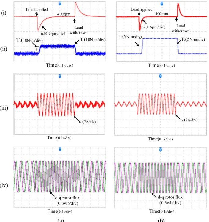
Fig. 12.The experimental starting characteristics of Linearized controlled induction motor drive scheme under 400 rpm without any load disturbance for (a) PI-torque controller (i) Speed (nr), (ii) torque (Te), (iii) stator current (ia), and (iv) rotor d-q flux, (b) ANFIS-torque controller (i) Speed (nr), (ii) torque (Te), (iii) stator current (ia), and (iv) rotor d-q flux.
Case4: Robustness studies of controllers:The load torque is fur-ther reduced to 5N-m for the same time instants of 1 s to 1.5 s and experimental analysis is carried out by altering the gain of speed-PI controller from kp/ki as 20/0.02–18/0.01 as shown inFig. 15. It reveals that even if the kpand kivalues of speed-PI controller are changed, unlike PI-torque controller as in Fig. 15a(i) and b(i), there is no such difference of speed response in terms of undershoot/overshoot and settling time by ANFIS-torque controller-based linearized drive as presented inFig. 15a(ii) and b(ii). Therefore, ANFIS-torque controller pro-vides substantial torque ripple minimization and less dip in speed subjected to quick dynamic response than that of
PI-torque controller based drive with the deviation of speed-PI controller gain. This shows extreme robustness and correctness because of the fact that the gain of PI controllers is tuned with proper optimization of rule by ANFIS controller using the center-of-gravity method. Apart from that the system shows excellent robustness and correctness using ANFIS-based torque controller over PI-torque controller so far as speed transition, load disturbance are concerned which is evident experimen-tally and from simulated performance results depicted in Table 1. Furthermore, at variable speed operations, i.e. from low-speed to high-speed operation, the torque and speed rip-ples for ANFIS-torque controller based drive are found to be
(i)
Load applied
400rpm
Load
withdrawn
T
e(
10N-m/div)
T
L(
10N-m/div)
Time(
0.1s/div)
n
r(0.9rpm/div)
Load applied
400rpm
Load
withdrawn
T
e(5
N-m/div)
T
L(5
N-m/div)
Time(
0.1s/div)
n
r(0.9rpm/div)
(ii)
(iii)
i
a(
7A/div)Time(
0.1s/div)i
a(
7A/div)Time(
0.1s/div)(iv)
Time(
0.1s/div)d-q rotor flux
(0.3wb/div)
(a)
Time(
0.1s/div)d-q rotor flux
(0.3wb/div)
(b)
Fig. 13.The experimental performance characteristics of Linearized controlled induction motor drive scheme under 400 rpm with a load disturbance of 10N-m for (a) PI-torque controller (i) Speed (nr), (ii) torque (Te), (iii) stator current (ia), and (iv) rotor d-q flux, (b) ANFIS-torque controller (i) Speed (nr), (ii) torque (Te), (iii) stator current (ia), and (iv) rotor d-q flux.
(i)
nr (400rpm/div) -400rpm 1000rpm Time(0.5s/div) 400rpm nr (400rpm/div) -400rpm 1000rpm Time(0.5s/div) 400rpm(ii)
Te(10N-m/div) Time(0.5s/div) Te(-10N-m/div) Te(6N-m/div) Time(0.5s/div) Te(-6N-m/div)(iii)
ia (7A/div) Time(0.5s/div) ia (7A/div) Time(0.5s/div) ia (2A/div) Time(0.025s/div) ia (2A/div) Time(0.025s/div)(iv)
d-q rotor flux (0.3wb/div) Time(0.5s/div)(a)
d-q rotor flux (0.3wb/div) Time(0.5s/div)(b)
Fig. 14.The experimental performance characteristics of Linearized controlled induction motor drive scheme under speed reversal for (a) PI-torque controller (i) Speed (nr), (ii) torque (Te), (iii) stator current (ia), and (iv) rotor d-q flux, (b) ANFIS-torque controller (i) Speed (nr), (ii) torque (Te), (iii) stator current (ia), and (iv) rotor d-q flux.
substantially reduced with well-controlled rotor flux as shown in results which prove the robustness of the controller.
Table 1shows the comparative analysis of performance of pro-posed ANFIS torque controller based linearized induction motor drive with the conventional PI-torque controller. The responses of ANFIS torque controller obtained from the results corresponding to ripple in speed with or without load, % undershoot and over-shoot of speed, torque ripples are found superior as compared to classical PI-torque controller. The integral time absolute error which is defined byITAE¼R01tjeðtÞjdt is found to be 0.8 in case of ANFIS controller, which is almost half of the PI-torque controller. It indicates as a good performance index for designing of con-trollers. Further, the settling time performance for rotor speed, tor-que and stator current obtained from the simulation as well as experiment at different time instant are depicted in theTable 1. This reveals that the system shows highly robustness towards the load perturbation, sudden speed change using ANFIS-torque controller based drive as compared to PI-torque controller.
The experimental results are found to be slightly higher value than that of simulated results because, some constraints like dead band, fluctuation of temperature, hard switching effect, variation of supply, electromagnetic interference phenomena, etc. cannot be ignored in real-time analysis.
9. Conclusion
The new design approach which incorporates ANFIS controller with decoupled feedback linearization based induction motor drive is articulated in this paper. The overall drive system was designed and modelled in MATLAB software and experimentally investi-gated in real-time hardware set-up using DSP TMS320F2812 processor.
The feedback linearized induction motor drive with ANFIS con-troller proves the robust and fast response with significantly reduced speed and torque ripple than that of the PI-torque con-troller as far as starting, load perturbation and speed reversal is concerned. However, the DC-link capacitor voltage is well balanced all through these operations without using any extra controller. Further, the flux responses all through these operations are main-tained almost constant. The performance index on ITAE indicates good responses in case of ANFIS-torque controller which can replace the conventional PI-torque controller.
Furthermore, an extensive experimental analysis has been car-ried out and the results provided and shown are closer to the sim-ulated results. Also, the adaptability and robustness of ANFIS scheme are proved experimentally by changing the gain of the speed-PI controller. Also, the results demonstrate the better response of flux and perfect decoupling when the proposed ANFIS
T
e(
5N-m/div)T
L(
5N-m/div) 400rpmn
r(
0.9rpm/div)Time(
0.1s/div)(i)
400rpmTime(
0.1s/div)n
r(0.9
rpm/div)T
L(
5N-m/div)Te(
5N-m/div)400rpm
(ii)
(a)
n
r(0.9
rpm/div)Time(
0.1s/div) 400rpmTe(
5N-m/div)T
L(
5N-m/div)(i)
n
r(0.9
rpm/div) 400rpmT
L(
5N-m/div)Te(
5N-m/div)Time(
0.1s/div)(ii)
(b)
Fig. 15.The experimental characteristics at load perturbation of 5N-m from 1 s to 1.5 s for different gains of speed PI-controller with (a) kp= 20 and ki= 0.02, (i) PI-torque controller based drive, (ii) ANFIS-torque controller based drive, (b) kp= 18 and ki= 0.01, (i) PI-Torque controller based drive, (ii) ANFIS-Torque controller based drive.
controller is implemented. The comparative performance analysis by simulation as well as experiment has been carried out under different operating conditions as given inTable 1, which shows, ANFIS controller scheme provides a robust and excellent perfor-mance over PI-torque controller based linearized induction motor drive without losing its decoupling characteristics, and thus, the proposed controller as a torque regulator is found to be suitable for high performance industrial induction motor drive application with a torque sensitive load.
Appendix A
Motor specifications Induction motor
1 Rated power Por 3.7 kw
2 Rated voltage VL-L 415 V
3 Rated speed nr 1445 rpm
4 Rated frequency fr 50 Hz
5 No. of pole pairs P 2
6 Stator resistance Rs 7.34X 7 Stator leakage inductance Lls 0.021 H 8 Rotor resistance Rr 5.64X 9 Rotor leakage inductance Llr 0.021 H 10 Mutual inductance Lm 0.5 H 11 Friction coefficient B 0.035 kg-m2/s 12 Inertia coefficient J 0.16 kg-m2 DC motor (load) 1 Rated power Pr 3.5 kw 2 Rated voltage V 220 V 3 Rated speed n 1500 rpm 4 Rated current i 18.5 A References
[1]J.J.E. Slotine, W. Li, Applied Nonlinear Control, Prentice Hall, 1991.
[2]B.K. Bose, Modern Power Electronics And AC Drives, Prentice Hall Of India, New Delhi, 2008.
[3]F. Blaschke, The principle of field orientation as applied to the new Transvector closed-loop control system for rotating-field machines, Siemens Rev. 39 (1972) 217–220.
[4]G.S. Kim, I.J. Ha, M.S. Ko, Control of induction motors for both high dynamic performance and high power efficiency, IEEE Trans. Ind. Electron. 39 (4) (1992) 323–333.
[5]H. Kubota, K. Matsuse, T. Nakano, DSP-based speed adaptive flux observer of induction motor, IEEE Trans. Ind. Appl. 29 (1993) 344–348.
[6]A. Isidori, A.J. Krener, C. Gori-Giorgi, S. Monaco, Nonlinear decoupling via feedback: a differential-geometric approach, IEEE Trans. Autom. Control 26 (1981) 331–345.
[7] Z. Krezminski, Nonlinear control of induction motor, in: Proc. 10th IFAC World Congress on Automatic Control, vol. 3, 1987, pp. 349–354.
[8]B. Charlet, J. Levine, R. Marino, Two sufficient conditions for dynamic feedback linearization, Analysis and Optimization of Systems, Lecture Notes in Control and Information Sciences, vol. 111, 1988.
[9]J. Chiasson, Dynamic feedback linearization of the induction motor, IEEE Trans. Autom. Control 38 (1993) 1588–1594.
[10]J. Chiasson, A new approach to dynamic feedback linearization control of an induction motor, IEEE Trans. Autom. Control 43 (3) (1998) 391–397.
[11] G. Luckjiff, I. Wallace, D. Divan, Feedback linearization of current regulated induction motors, in: Proc. IEEE PESC, 2001, pp. 1173–1178.
[12]T.K. Boukas, T.G. Habetler, High-performance induction motor speed control using exact feedback linearization with state and state derivative feedback, IEEE Trans. Power Electron. 19 (4) (2004) 1022–1028.
[13]K.J. Astrom, T. Hagglund, PID Controllers: Theory, Design, and Tuning, Second Edition., Instrument Society of America, The International Society for Measurement and Control, 1995, p. 166.
[14]C.C. Lee, Fuzzy Logic in Control Systems: Fuzzy Logic controller – Part 2, IEEE, 1990.
[15]S.A. Mir, D.S. Zinger, M.E. Elbuluk, Fuzzy controller for inverter fed induction machines, IEEE Trans. Ind. Appl.30 (1) (1994) 78–84.
[16]S. Padmanaban, J.L. Febin Daya, F. Blaabjerg, N. Mir-Nasiri, A.H. Ertas, Numerical implementation of wavelet and fuzzy transform IFOC for three-phase induction motor, Eng. Sci. Technol. Int. J. 19 (1) (2016) 96–100. [17]V. Utkin, J. Guldner, J. Shi, Sliding Mode Control in Electromechanical Systems,
Taylor & Francis, 1999.
[18]C. Lascu, I. Boldea, F. Blaabjerg, Variable-structure direct torque control – a class of fast and robust controllers for induction machine drives, IEEE Trans. Ind. Electron. 51 (4) (2004) 785–792.
[19]F.J. Lin, R.J. Wai, Robust control using neural network uncertainty observer for linear induction motor servo drive, in: IEEE Trans. Power Electron. 17 (2002) 241–254.
[20] M.P. Kazmierkowski, D. Sobczuk, Sliding mode feedback linearization of PWM inverter fed induction motor, in: Proc. IEEE IECON, vol. 1, 1996, pp. 244–249. [21]M.N. Uddin, M.A. Abido, M.A. Rahman, Development and implementation of a hybrid intelligent controller for interior permanent magnet synchronous motor drive, IEEE Trans. Ind. Appl. 40 (1) (2004) 68–76.
[22]C.T. Lin, C.S.G. Lee, Neural Fuzzy Systems: A Neuro-Fuzzy Synergism to Intelligent Systems, Prentice-Hall, Englewood Cliffs, NJ, USA, 1996. [23]G.W. Chang, G. Espinosa-Perez, E. Mendes, R. Ortega, Tuning rules for the PI
gains of field-oriented controllers of induction motors, IEEE Trans. Ind. Electron. 47 (3) (2000) 592–602.
[24]M. Najafzadeh, Neuro-fuzzy GMDH based particle swarm optimization for prediction of scour depth at downstream of grade control structures, Eng. Sci. Technol. Int. J. 18 (2015) 42–51.
[25]M.N. Uddin, H. Wen, Development of a self-tuned neuro–fuzzy controller for induction motor drives, IEEE Trans. Ind. Appl. 43 (4) (2007) 1108–1116. [26]M.N. Uddin, M.I. Chy, A novel fuzzy logic controller based torque and flux
controls of IPM synchronous motor, IEEE Trans. Ind. Appl.46 (3) (2010) 1220– 1229.
[27]Z. Zhang, R. Tang, B. Bai, D. Xie, Novel direct torque control based on space vector modulation with adaptive stator flux observer for induction motors, IEEE Trans. Magn. 46 (8) (2010) 3133–3136.
[28]K.P. Venugopal, R. Sudhakar, A.S. Pandya, An improved scheme for direct adaptive control of dynamical systems using back propagation neural networks, J. Circuits Syst. Signal Process. 14 (2) (1995) 213–236.
[29]P.Z. Grabowski, B.K. Bose, F. Blaabjerg, A simple direct torque neuro fuzzy control of PWM inverter fed induction motor drive, IEEE Trans. Ind. Electron.
47 (4) (2000) 863–870.
[30]J.S.R. Jang, ANFIS: adaptive-network-based fuzzy inference system, IEEE Trans. Syst. Man Cybern. 23 (3) (1993) 665–685.
[31]M.N. Uddin, Z.R. Huang, A.B.M.S. Hossain, Development and implementation of a simplified self-tuned neuro–fuzzy-based IM drive, IEEE Trans. Ind. Appl. 50 (1) (2014) 51–59.
[32] R.N Mishra, K.B. Mohanty, Performance enhancement of a linearized induction motor drive using ANFIS based torque Controller, in: Proc. 12th India Int. Conf. (INDICON-15), 2015, pp. 17–20.
[33]N. Venkataramana Naik, S.P. Singh, Comparative analytical performance of F2DTC and PIDTC of induction motor using DSPACE DS-1104, IEEE Trans. Ind. Electron. 62 (12) (2015) 7350–7359.
[34]X. Duan, H. Deng, H. Li, A saturation-based tuning method for fuzzy PID controller, IEEE Trans. Ind. Electron.60 (11) (2013) 577–585.
[35]G. Durgasukumar, M.K. Pathak, Comparison of adaptive neuro-fuzzy based space vector modulation for two-level inverter, Int. J. Electr. Power Energy Syst. 38 (1) (2012) 9–19.
[36]N. Venkataramana Naik, Jose Thankachan, S.P. Singh, A neuro-fuzzy direct torque control using bus-clamped space vector modulation, IETE Tech. Rev. (2015).
[37]T. Ramesh, A.K. Panda, Type-2 fuzzy logic control based MRAS speed estimator for speed sensorless direct torque and flux control of an induction motor drive, ISA Trans. 57 (2015) 262–275.
[38]B. Dandil, Fuzzy neural network IP controller for robust position control of induction motor drive, Expert Syst. Appl. 36 (3) (2009) 4528–4534.