Improved Stability of Haptic Human-Robot Interfaces using
Measurement of Human Arm Stiffness
William Gallagher
Dalong Gao
Jun Ueda
Bio-Robotics & Human Modeling Lab School of Mechanical Engineering
Georgia Institute of Technology Atlanta, Georgia 30332 Email: [email protected] Email: [email protected]
Manufacturing Systems Research Lab General Motors Research & Development
Warren, Michigan 48092 Email: [email protected]
Abstract
Necessary physical contact between an operator and a force feedback haptic device creates a coupled system consisting of human and machine. This contact, combined with the natural human tendency to increase arm stiffness to attempt to stabilize its motion, can reduce the stability of the system. This paper proposes a method to increase stability on demand while maintaining speed and performance. Operator arm stiffness is not directly measurable, so controllers cannot typically account for this issue. The causes of arm end-point stiffness are examined as related to system stability, and a method for estimating changes in arm stiffness based on arm muscle activity was designed to provide a robotic controller with additional information about the operator. This was accomplished using EMGs to measure muscle activities and estimating the level of arm stiffness, which was used to adjust the dynamic characteristics of an impedance controller. To support this design, the correlation between EMGs and arm stiffness was validated experimentally. Further experiments characterized the effects of the designed system on operator performance. This showed increased stability and faster, more accurate movements using the compensating system. Such a system could be used in many applications, including force assisting devices in industrial facilities.
1
Introduction
Industrial settings are increasingly utilizing robotics and automation to streamline difficult jobs. How-ever, some situations make the use of automated robots difficult due to the high cost of automation in a flexible manufacturing environment. Vehicle assembly lines are one example of this situation, where the placement of a vehicle component, such as a door, must be done within tolerances, but the location of the vehicle itself may vary since it may be carried on a moving line. In this case, it is still more efficient to have a human accomplish the task. However, components such as a car door can be heavier than a worker can lift. For this reason, force assistive devices can be useful in aiding the completion of this and other similar tasks. While teleoperated systems could also be used, a remote operator and added system components, including sensing, increase cost and complexity, and result in slower task completion in a production environment. Therefore, a system that the operator could directly interact with is preferred. Haptic controllers are a popular method because operators find touch to be a very intuitive way for controlling a robotic device. However, requiring physical contact between the operator and the robot introduces force feedback and creates a coupled operator-robot system. Various studies have shown that the natural response of a human operator under this coupling results in reduced stability if not properly controlled. This instability can increase task completion time and decrease performance, making the job of the robot operator more difficult. To avoid such situations, human operators will commonly stiffen their arm to try to control any oscillation of the device. This creates a stiffer coupled system, which leads to more instability. Since generic robot controllers can’t directly measure the level of operator stiffness, most cannot adjust to such changes. A system that could access information about the operator and their method for interacting with the robot could adjust accordingly, and thereby increase stability, bolster operator and load safety, and make the task of the operator easier.
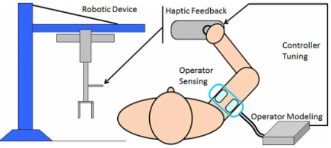
As a proposed solution, this research aims to develop a method that will allow a haptic robot controller to adjust to changes in the manner in which the operator is interacting with the robot by expanding the information available about the operator to the controller. Figure 1 shows a conceptual illustration of how the system should operate. The designed system will measure a variety of metrics that have been shown to be indicative of how the operator is intending to move the device, and incorporate them into a model of the operator. This model will then estimate the operator’s current motion, which can be used to adjust the gains of the robot’s controller to assist the operator. Modeling the operator in this way allows the robot to actively adjust to changes in the way the operator moves, ensuring stability and ease of use. The results of this research could be used in the design and control of various human-machine interfaces with applications to many areas of robotics, such as industrial assembly lines robots or space robots.
Figure 1: Conceptual drawing of a haptically controlled robotic device with a controller that adjusts based on estimated operator intention
2
Background
2.1
Haptic Stability
Haptic systems, which require physical human robot interaction, create a coupled and bilateral system in which the device responds to the force applied by the operator and the operator adjust the applied force based on the device’s motion. Some haptic systems attempt to resist the motion of the operator so as to provide a virtual environment for them to feel [1, 2, 3, 4], while many attempt to amplify the motion of the operator so as to enable increased capabilities [5, 6, 7, 8]. Force assisting devices are the primary concern for this research, but some studies relative to other types of haptic devices may also be applicable. In all cases, the device is controlled based on the measured force applied by the operator.
Devices using force control have been shown to become unstable under contact with stiff environments or the presence of a time delay, both of which are often present under contact with a human operator [9, 10, 11]. Human reaction times can be orders of magnitude larger than the typical period of a single control loop, and the demonstrated human reaction under instability is to increase contact stiffness. In addition, sensor time delays introduce further sources of instability into the system. Introducing compliance into the robotic system can mitigate this issue, but this inherently decreases performance of the system, a trade off which has been well documented [12, 9, 10, 11]. Since the goal of the designed system is to increase performance, introducing a measure of compliance to the robot system would not be beneficial.
Stability of human-robot interaction using haptic systems has been analyzed using both root-locus methods [11] and Lyapunov theory [10]. These studies provided useful stability bounds, which were highly dependent on the stiffness of the human operator. However, these studies do not account for deliberate stiffening of the human operator’s arm, and therefore are not sufficient for this design, which requires further stability analysis. The stability of teleoperation systems is often viewed from the perspective of passivity, and this has been extended to haptic devices as well [9, 1, 13, 14, 15, 16]. While this could provide a useful condition for the stability of a system, force assisting devices are by nature not strictly passive [8]. Several more recent studies have combined these two methods in a way that could be applicable to analyzing haptic force assistive systems [2, 3]. Studies have explored the design of robust controllers for interacting systems and teleoperation [17, 18, 12, 19, 16], but require a priori
knowledge of the range of the system parameters.
2.2
Operator Arm Stiffness
Under typical control situations, an operator’s arm stiffness is not directly measurable. Stiffness is defined as the change in force over a change in distance from a given neutral point, and while the applied force is readily measurable with sensors, the change in distance is not. This is because as the operator moves, the neutral point moves as well. In addition, there are several different stiffnesses related to the motion of the human arm: a) muscle stiffness - the resistance of a single muscle to changes in length;b) joint stiffness - the resistance of a joint to changes in joint angle; and c) endpoint stiffness -the resistance of -the entire arm to changes in end-point location. End-point stiffness is of most interest for the design of the robotic controller, but it is affected by both individual muscle stiffnesses and joint stiffnesses.
The basis of much of our understanding of human muscles comes from Hill’s work, which models mus-cles primarily as springs with a force generation component, as well as Bernstein’s discussion of human motor control [20]. Muscles accomplish a variety of functions, acting as force generators and brakes to allow human locomotion [21], but their spring properties are of particular interest in understanding arm stiffness. It has been well established that muscles resist a change in length when contracting [22, 23]. Studies on their elastic properties have found that the spring constant of muscles is a nonlinear function of both generated force and length [24]. In addition, muscle stiffness can be separated into an intrinsic static component and a reflex-based component [25, 26, 27, 28]. The static component acts much like a traditional spring under a displacement, instantly supplying a force tending towards returning to the pre-displacement length. The reflex component of stiffness comes from the nervous system’s reaction to an unintended change in muscle length, causing the muscle to generate more force to return to the pre-displacement length. This component is not instantaneous, but takes a small amount of time to respond. Under dynamic situations, large velocities can further change the intrinsic stiffness of the muscle [29]. In general, however, a muscle generating a larger force will exhibit a higher stiffness.
Since muscles can only provide contractive force, joints in the body normally have two or more opposing antagonistic muscles. Increases in joint stiffness have been linked to simultaneous activation of these muscles, or cocontraction [30, 31]. This leads to an increase in both force and stiffness of each muscle without a net change in torque on the joint. Since a change in joint angle would lead to a change in the length of both muscles, this thereby increases the stiffness of the joint. This has been experimentally verified on many joints, including, the ankle, wrist, the trunk [32, 33, 34, 35, 36, 37, 38]. From a mechanical point of view, arm end-point stiffness is simply the result of several springs in series, since the stiffness of each joint affects the overall stiffness of the end-point [39]. Therefore, any increase in joint stiffness will cause an increase in end-point stiffness. For this reason, cocontraction of antagonistic muscles in the arm will lead to higher end-point stiffness. An important consideration, however, is that the moment arm of a particular muscle on a given joint changes as the arm posture
changes, so the stiffness of a joint will vary based on posture [40], affecting the end-point stiffness of the entire arm [41]. Several studies have shown that people generally can not control end-point stiffness independently of force and position [39, 42, 43], which implies that an estimate of end-point stiffness is indicative of either involuntary reactions to the environment or an intended voluntary applied force and motion. In general, these studies found a roughly linear increase in end-point stiffness with voluntary force.
The nonlinear effects of muscle activity on the motion and stiffness of a muscle are demonstrated in Hatze’s thorough model of muscular motion [44, 45]. In his work, a complete force model of a muscle is developed as a function of muscle activity and activation rate, in which the the length and force of a muscle vary in a complex nonlinear fashion based on these two parameters. Similarly, the model presented by Zajac illustrates this nonlinearity [46]. Both authors show how the elastic properties of a muscle are influenced by the dynamic motion of the muscle. Since force and length vary based on muscle activity, and stiffness has beens shown to be a nonlinear function of these two [24], it might be questioned how a linear approximation of muscle stiffness could be useful. However, both Hatze and Zajac go on to discuss a simplified model which can linearly approximate a muscle’s motion for a specific region away from the extremes of length and force, which corresponds to muscle activations of up to approximately one third of the maximum activation. In this region, therefore, it is reasonable to approximate a muscle with a linear spring.
Numerous studies have evaluated the response of humans to unexpected perturbations or instability when trying to control an object. It has been demonstrated that the brain attempts to correct for an inability to maintain a desired target by increasing arm stiffness, which is a result of increased cocontraction [47, 48, 32, 49, 50, 51, 36], and has a similar response when trying to resist movement [52, 53]. Also, the reverse has been demonstrated during smooth movements or when not trying to resist motion, which result in lower stiffness with less cocontraction [47, 32]. Therefore, for the purpose of designing a system to detect the body’s reaction to unstable situations, it should be possible to measure the level of cocontraction in the operator’s arm and use it as an indication of stiffness level.
Other studies have endeavored to measure the dynamic characteristics of human joints [54], and often the human arm can be modeled as a mass-spring-damper system for the purposes of haptic control interfaces and human robot interaction [10, 55, 11]. Estimating stiffness requires a measure of muscle activity, so that cocontraction levels can be calculated [56, 57, 53]. Electromyogram (EMG) measurements have frequently been used to record muscle activity, and have been used for stiffness estimates [58, 59]. Alternatives have been proposed, such as introducing small vibrations into the motion of the device to obtain an indirect measure of arm stiffness [60]. This technique shows promise, but has some drawbacks for the types of systems this research is looking to control. Most importantly, introducing additional vibrations into a force amplifying system is undesirable. As the focus of this research is on the control techniques of using the estimated stiffness, the actual method by which stiffness is measured is flexible. Therefore, future work may be able to take advantage of such alternative sensing techniques to further simplify the design.
Figure 2: The 51 arm muscles included in the musculoskeletal model [65]
Figure 3: The 9 arm joints included in the mus-culoskeletal model with important muscles [65]
3
Method
3.1
Muscle Activity
Prior work by Ueda and Ding [61, 62, 63, 64, 65, 66, 67] involved developing a computer model of the human musculoskeletal system in the upper body and arms. Figure 2 and Figure 3 show the complete model of the arm. Several candidate muscle groups that could provide the necessary cocontraction information were identified using this model by comparing the effect of various muscles on the wrist and elbow joints to determine the best antagonistic pairs to use. Each muscle’s contribution to the torque on the arm joints can be represented using the moment arm matrix, A, such that the joint torques, τ, may be calculated if the muscle forces, f, are known. Equation (1) gives this relationship, where A is M ×N,τ is of lengthM, and f is of lengthN for a human musculoskeletal model that has M
joints and N muscles. For this model, M = 9 and N = 51. The contribution of a single muscle is given by its moment arm vector, aj, which is the corresponding column of A. The angle between two muscles’ moment arm vectors can be found by taking the inner product as shown in Equation (2). Two completely antagonistic muscles would directly oppose one another, resulting in an angle of 180◦.
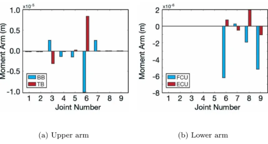
τ =Af (1) α= cos−1 haj1,aj2i ||aj1|| ||aj2|| = cos−1 a T j1aj2 ||aj1|| ||aj2|| (2) In reality, each muscle contributes to the torque on multiple joints, so very few muscle pairs yield such direct antagonism. However, several good candidate pairs emerge from the primary muscles of the wrist and elbow. Ultimately, one pair from each was chosen, with the first being the biceps brachii (BB) and triceps brachii (T B) in the upper arm and the second being the flexor carpi ulnaris (F CU) and extensor carpi ulnaris (ECU) in the lower arm. Each of these is shown in Figure 3 The moment arms of the
BB/T B pair are compared visually in Figure 4(a) and yield an angle of 163◦. It can be seen that these two muscles primarily affects joint 6, while also significantly affecting joint 3. In both cases, the effect
(a) Upper arm (b) Lower arm
Figure 4: Comparison of the moment arms for each antagonistic pair (See Figure 3 for joint numbers)
ofT Bis opposite and nearly equal to that ofBB. BB also has some effects on joints 4, 5, and 7, which explains why the angle is not a perfect 180◦. Conveniently, bothBB andT B are close to the skin and easily measured using surface electrodes. Similarly, the F CU/ECU pair are compared in Figure 4(b) and yield and angle of 100◦. This pair does not exhibit the same level of perfect antagonism asT B and
BB, but it is still clear that they act in opposite direction from each other. Both muscles have the same not insignificant effect on joint 9, which leads to an angle that is farther from 180◦ than the previous pair. However, neglecting this joint and considering only the first 8, an assumption that will be justified by the design of the hardware, the muscles give an angle of 127◦, which is a significant improvement. An
alternative antagonistic pair in the wrist, the Flexor Carpi Radialis (F CR) and Extensor Carpi Radialis (ECR) provides an angle of only 96◦, which improves to only 114◦ when neglecting joint 9, and any other candidate muscles are not close enough to the skin to obtain accurate EMG readings with surface electrodes [68, 69].
3.2
Stiffness Compensation
To measure the level of cocontraction, one pair of electrodes was placed on each of four muscles chosen (T B, BB, F CU, ECU), and an additional ground electrode was placed on the elbow. The EMG signals were used to calculate a measure of cocontraction for each antagonistic pair (Elbow, E; Wrist,
W). The raw EMG signal for a given muscle,Ej(t),j=T B, BB, F CU, ECU, was filtered and rectified, resulting in the processed signalEj∗(t). To calibrate this, the maximum voluntary force (MVF) of each muscle,EM V F
j (t), was measured by having the user generate the maximum force in their arm through an isometric contraction, and then was processed in the same manner. The processed signal was then normalized by its MVF as given by (3) to give the percent effort of a muscle, E%
j (t). Finally, the cocontraction of each muscle pair,Ck(t),k=E, W, was found by taking the minimum level that both muscles of the pair were contracted to, as shown by (4).
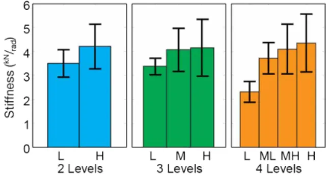
Figure 5: Average of classified stiffness levels for experimental data, error bars show standard deviation of classified points. Ej%(t) = Ej∗(t) EM V F j (3) CW(t) = minEF CU% (t), E % ECU(t) CE(t) = minE% BB(t), E % T B(t) (4)
Using the cocontraction level calculated, the stiffness, S, of the operator’s arm was classified into discrete levels. This method was chosen because the noise in the EMG readings made a continuous stiffness scale difficult to implement. Testing indicated that a simple classification of the stiffness as high or low gave the best results for the initial design. This was done using a simple adjustable threshold,
tk, for each pair of muscles based on (5), allowing the system to be tuned to the differences in each user. This evaluations was completed by calculating the stiffness of subjects using the device while force and position were controlled, with a mean value of ko= 2.8kN/rad and the range 0.4kN/rad≤s≤8.4kN/rad encompassing 95% of the data (It was not characterized by a normal distribution). Figure 5 shows the distribution of stiffness points as classified based on the measured cocontraction. Classifying with more than two levels using evenly distributed thresholds gave little significant difference between the higher levels, and the best performance was obtained with only two levels.
S= high ifCW(t)≤tW andCE(t)≤tE low ifCW(t)> tW or CE(t)> tE (5)
To avoid excessive oscillation between states, the state only changed when the cocontraction level crossed the threshold for some finite amount of time. EMG measurements are highly amplified because of the very small voltages that are measured in human muscles, which causes a high level of noise. The signals were therefore filtered as described above, adding to the time that the signal must exceed the threshold to be registered and helping reduce chatter.
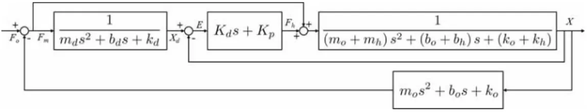
Figure 6: sdomain block diagram of impedance controller and operator system
3.3
Haptic Device
Many haptic systems use impedance control, which generates an assistive force so as to mask the actual system dynamics and allow the operator to feel a desired system with an arbitrary set of dynamic characteristics [70]. Modeling the operator as a system with mass, mo, damping, bo, and stiffness,ko, applying a force, fo, and the haptic device as having mass, mh, damping, bh, and stiffness, kh, and capable of measuring the applied force, fm, then (6) is the equation of motion of the contact point of the operator with the device and (7) is the equation of motion of the device itself. The control force,
fh, is determined based on the desired mass,md, damping,bd, and stiffness,kd, as given by (8). From these follows the derivation of the equation of motion in (9), which demonstrates how the controller can mask the device’s dynamics. This makes the load on the user lighter and allows easier operation, which, when combined with haptic feedback, can give a very natural feeling to operating the robot. An impedance controller incorporates an outer force controller that finds the change in position, xd, that the desired system would exhibit under the applied loading, with an inner position controller loop that attempts to drive the error, e, between this and the device position, x, to zero. Often, the stiffness of the desired system is set to zero, which would result in the transfer function for the outer block as given by (10). The inner block can be any position controller, such as a PD controller with proportional gain
Kp and derivative gainKd.
fo−fm=mox¨+box˙+kox (6) fh+fm=mhx¨+bhx˙ +khx (7) fh = (md−mh) ¨x+ (bd−bh) ˙x+ (kd−kh)x (8) fo = (mo+md) ¨x+ (bo+bd) ˙x+ (ko+kd)x (9) Xd(s) Fm(s) = 1 mds2+bds (10) Figure 6 shows the complete system, including controller, device, and operator characteristics. To account for the fact that the measured force may not exactly equal the actual force applied to the handle, a feed forward element is included to transmit the applied force to the device. The impedance controller takes the measured force to calculate the desired motion, xd, which is passed to the position controller. The motion of the device and operator are coupled, and the operator dynamics close the force loop, creating additional feedback.
Figure 7: One degree of freedom haptic feedback device
Table 1: Controller Parameters
Kp 2500Nm/rad Kd 200Nms/rad bdh 1Ns/m mdh 1×10⁻⁴kg
bdl 1×10⁻⁸ Ns/m mdl 4×10⁻⁵kg
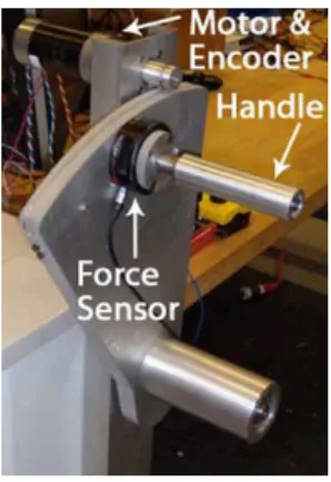
A simple one-degree-of-freedom haptic paddle [71, 72, 73, 74, 75, 76] was produced for the purpose of implementation and testing, shown in Figure 7. This design was chosen for versatility and low cost, and was scaled up for increased force capability. A cable drive system ensured compliance to the forces applied by the a human operator while also amplifying the force produced to the motor. The device generates up to 100 N of force with a frequency response of up to 10 Hz.
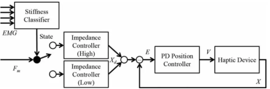
Two sets of impedance characteristics were experimentally determined based on the desired motion of an industrial force assisting robot for each stiffness case, shown in Table 1. Low arm stiffness should allow quick and easy motion with little resistance, so the mass and damping were set to be small. High stiffness should give less oscillation and allow more precise motion by the operator, so damping and mass were higher. The gains of the PD position controller did not change based on the stiffness classification. Based on the classifier output, either the high or low characteristics, bdh and mdh or bdl and mdl respectively, were chosen for the impedance controller’s desired characteristics, bd andmd, as given in (11). The whole system is shown in the block diagram in Figure 8. The position of the device is controlled solely by the force applied to the device as with a standard impedance controller. However, additional data in the form of the arm stiffness is used to adjust the way in which the controller performs. EMG data does not directly affect the output of the device, as that would cause a bilateral interaction, with a change in force of the device affecting the muscle activity that is used to calculate that force.
bd md = bdl mdl > ifS=low bdh mdh > ifS=high (11)
Figure 8: Block diagram of the complete control system
4
Evaluation
4.1
Stability analysis
Based on Figure 6, the characteristic equation of the system can be derived. Due to the nature of the contribution of the operator stiffness, ko, it cannot be isolated to be the loop gain of a unity-feedback system. Therefore, the analysis is based on the closed-loop poles and zeros of the system, withkovaried to determine its effect on stability. The characteristic equation given by (12) - (16) gives Figure 9, which shows theses poles and zeros using both the low and high stiffness case parameters with zero operator stiffness. The trajectories indicate the movement of the poles as stiffness increases. When the operator stiffness is zero, all poles and zeros lie in the left half plane. As stiffness increases, the two real poles lying close to zero move leftward towards the zeros lying on the real axis. However, the two complex poles move into the right half plane and approach infinity, demonstrating the destabilizing effect of increased operator arm stiffness. Increasing the damping characteristic of the impedance controller, bd, as was done for the high stiffness case, moves the complex poles to the left, while increasing the mass,md, slows the rate at which they move, keeping the system stable for higher stiffness values. The square in Figure 9 show this for a fixed ko = 4.0kN/rad, which based on the data collected, is a typical value for high stiffness. In addition, force sensor data must be filtered, introducing a delay into the controller when converting to a discrete time system for implementation, adding an additional destabilizing influence.
X(s) Fo(s) = A(s) B(s)C(s) +koD(s) (12) A(s) = mds2+ (bd+Kd)s+Kp (13) B(s) = mds2+bds (14) C(s) = mhs2+ (bh+Kd)s+Kp (15) D(s) = 2mds2+ (2bd+Kd)s+Kp (16)
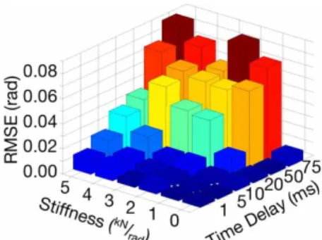
Using the haptic device it was possible to reproduce the conditions under which the system grew unstable as operator arm stiffness increased. Figure 10 plots the magnitude of device oscillation while the operator attempts to hold the device steady. The time delay for the force feedback and the stiffness of the operator’s arm were independently varied to characterize the stability of the device. As either
Figure 9: Zeros and closed-loop poles: All in left half for zero stiffness; Increased stiffness moves complex poles into right half (trajectories); In-creased damping moves poles left (squares, poles for fixedko= 4.0kN/rad)
Figure 10: Larger oscillations (higher RMS error) as time delay and stiffness increase (red - large oscillations, blue - no oscillation)
variable increased, the magnitude of the uncontrollable oscillation grew, as indicated by the red bars near the back of the plot. With no time delay and minimal stiffness, the device was much more stable, as indicated by the dark blue bars near the origin. This shows that the increased stiffness and time delay combine to prevent the system from remaining stable. Future work will incorporate the time delay concerns into the analytical model of the system to characterize its contribution to instability further.
This simple pole-zero analysis, using the operator stiffness as the variable gain, demonstrates the contact instability in such devices, which is corroborated by experimental results. Passivity based analyses could provide sufficient criteria for stability, but tend to be very conservative, whereas the traditional pole-zero method is not. It is possible for a system to fail to meet passivity criteria and still remain stable. In addition, since force assistive devices are not strictly passive, such an analysis may break down for situations with contact induced instabilies that are not well modeled, as has been demonstrated by Li in his work with passivity and force assisting devices [15, 8]. Therefore, satisfying these conservative criteria or implementing a robust controller would result in a compromise in the desired performance of the system.
4.2
EMG Validation
The use of EMG signals was experimentally validated to ensure this methodology, which is simplified from what previous studies have done, is justified. The stiffness, kθ, can be calculated from (17) if the base of a spring was fixed and the position, xe and applied force, fe, of the end were known. By controlling these values, only the EMG signal must be measured. The assumption of linearity can be maintained for consistent posture and low velocity [40, 41]. This procedure was developed based on that used by several other studies [56, 57, 58, 59, 53, 42, 43, 39, 77].
Participants held the device handle while position and force were controlled independently. Stiffness, the desired independent variable, was directly calculated by recording their difference from the control inputs and modeled as an intermediate variable, while th EMG signal for each muscle was recorded. It was expected that the EMG signals and stiffness would covary throughout the experiment. To verify this exhaustively, several stiffness values were tested. Therefore, the force was varied at twenty levels evenly spaced from 5 N to 100 N, and the handle position at three levels of−20◦, 0◦, and 20◦.
Since stiffness was the main value of interest, the individual combinations of force and position were not expected to influence the results significantly. However, the human arm is not necessarily a linear system, and it is possible that human muscles could exhibit other unexpected tendencies. The most exhaustive design that fully crossed the levels of force and position was used, leading to sixty cases. Each person’s size and strength varied, introducing extraneous variables that complicated comparisons between individuals. For this reason, each experiment participant was asked to perform multiple trials of the experiment, covering all of the sixty cases. It was expected that each participant’s results would follow the same general trend.
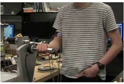
Participants held device as shown in Figure 11. They were asked to hold the device stationary in the given position, then it applied a force against them. This required them to stiffen their arm to continue to hold the device in place, as recorded by the EMG sensors. Learning effects associated with the task were expected to be insignificant due to its simple nature. The data was analyzed to look for correlations between stiffness and EMG signal. This experiment was performed following an approved Institutional Review Board (IRB) protocol.
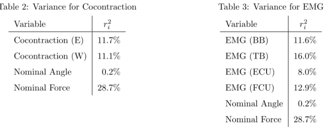
A multiple regression/correlation (MRC) technique was used as in Cohen [78] to look for a relation-ship between cocontraction and arm stiffness. Another MRC was calculated using all four EMG signals as predictors instead of the two cocontractions for completeness. For both, the nominal values of device position and generated force were included to measure their influence on the relationship. To avoid measuring voluntary forces applied by the participant, only the first 200-300 ms of each trial was used for the analysis. The values of the multiple correlation coefficient,R2, (indicating the quality of the fit)
and the zero-order correlation coefficients for each predictor, ri2’s, (indicating predictori’s influence on the predicted variable’s variance) were found. The results were expected to indicate a statistically sig-nificant relationship between cocontraction and stiffness and comparable results between EMG signals and stiffness, with no significant contribution to the variance of stiffness from position or force. The
Table 2: Variance for Cocontraction Variable r2 i Cocontraction (E) 11.7% Cocontraction (W) 11.1% Nominal Angle 0.2% Nominal Force 28.7%
Table 3: Variance for EMG
Variable r2 i EMG (BB) 11.6% EMG (TB) 16.0% EMG (ECU) 8.0% EMG (FCU) 12.9% Nominal Angle 0.2% Nominal Force 28.7%
data from all participants was anonymized and processed using MATLAB, while SPSS and G*Power 3.1 [79] were used for statistical analysis.
The number of participants was chosen based on the desired power, 1−β, of the resulting statistical analysis, which indicates the chance of statistical errors, β. Often chosen as 1−β = 0.95, leaving a 5% chance of errors, a value was chosen for this experiment due to the very large amount of data collected (well in excess of 200 points). Trial data was filtered down to 10 points, which reduced noise without masking the main effects in the signal, giving 600 data points per subject. 1−β = 0.9999 required approximately 1,500 data points, resulting in a 1 in approximately 10,000 chance of error and requiring at least three participants. A total of four subjects participated, giving roughly 2,000 points. All participants were male ranging in age from 20 to 26. Due force sensor limits, trials with very high forces were not accurately read, reducing the number of usable data points to approximately 1,200, giving 1−β= 0.9976 and a required criticalF = 4.69 for statistical significance of the regression.
The MRC method resulted in a cocontraction/stiffness relationship utilizing a logarithmic transfor-mation that achieved R2 = 0.338. Table 2 lists the variance of the stiffness partitioned amongst the predictor variables, indicating the degree to which each predictor contributed to a change in stiffness. The regression resulted in F = 75.8. The EMG/stiffness relationship with a similar transformation resulted inR2= 0.377 andF = 59.8, and the corresponding partitioning of the variance of the stiffness
is shown in Table 3. Both regressions were statistically significant. Initial results not utilizing a logarith-mic transformation provided a poorer fit, and since the fundamental form of the relationship between muscle activity and arm stiffness was unknown, data transformations such exponential and logarithmic were tested, with logarithmic providing the best fit.
The results indicated a statistically significant relationship exists that allows the use of measured EMG signals as a predictor of the operator’s arm stiffness. The fit using the cocontraction provided a slightly poorer fit than the raw EMG data, indicating that further analysis should be done about how to characterize cocontraction from muscle activity. The starting position of the device accounted for only 0.2% of the variance, as expected. However, the nominal force of each trial had a much larger effect on the regression than anticipated.
(a) Movement between two targets
(b) Contact with rigid surface
Figure 12: Comparison of response without compensation, top, and with compensation, bottom (high-light indicates high stiffness)
4.3
System Validation
In Figure 12(a) and Figure 12(b), the top graph shows the motion of the device using a standard impedance controller, and the bottom graph shows the same motion with the new system, with the yellow highlight indicating the system has detected higher operator arm stiffness and is compensating for it. First, the haptic device was moved back and forth between two target positions. The graph showing the compensating controller illustrates the increased stability and smoother motion without sacrificing the ability to move the handle rapidly over long distances, whereas without compensation, stopping at the target and reversing directions smoothly was more difficult. Next, the device was held against a rigid surface. Without compensation, the device oscillates rapidly under the stiff conditions. However, with the compensation, the device can be easily held against the rigid surface. The root mean square error (RMSE) of the distance from the surface for went from 2.22×10⁻² rad to 9.90×10⁻³ rad with the compensation, a decrease of 60%.
Evaluation of the compensating controller required testing the effects on both stability in a stiff situation and operator performance in a typical usage scenario.
Haptic devices are difficult to hold against a rigid surface due to the reaction force of contact between the two. When an operator attempts to do so, the device repeatedly bounces off the surface and becomes unstable. It was expected that the operator would stiffen their arm to hold the device against the surface, so the damping coefficient would increase when the compensation was on, stabilizing the system when needed. Participants were asked to hold the device against a fixed rigid surface with and without the compensating controller, and the device position was recorded over time. To measure the stability of
Figure 13: Mean and variance of RMSE data for compensation on and off: Participants showed a significant decrease with compensation on
Figure 14: Compensation on RMSE as fraction of compensation off shows decrease for all partic-ipants
the system, the root-mean-square error (RMSE) of the distance to the surface was calculated for each attempt, which was expected to be minimal for a goal of maintaining contact with the surface. Each participant was oriented with the EMG measurement system and haptic device, and then had the EMG measurement system connected. After using the device for a short time to minimize learning effects, participants were asked to place the handle of the device against a rigid surface and hold it in contact for five seconds. This was repeated several times with the compensation both on and off. The results were analyzed by the ANOVA method to find statistically significant differences between controller states.
The number of participants was chosen based on the desired power, 1−β, of the resulting statistical analysis, which indicates the chance of statistical errors, β, with a typical target power 1−β = 0.95. This required a minimum of 16 participants to obtain statistically significant results. The experiment included 20 participants, with 12 males and 8 females ranging from age 19 to 37, resulting in 1−β= 0.965 and a required critical F = 1.29 for statistical significance. This was performed followed an approved IRB protocol.
As demonstrated by Figure 13, participants were able to reduce the average RMSE with the com-pensation on. The ANOVA analysis resulted in F = 55.72 and p ≤ 0.05, demonstrating statistical significance.
To mimic a real-world usage scenario involving large force assisting devices, participants were asked to accomplish a pick-and-place task by using the haptic device to control a simulated lifting arm. The operator pressed a button to lower the arm and pick up an object, then move the arm to a target and put the object down. Figure 15 shows the simulation. The task was performed for both controller states, and the distance of the object’s initial location to the target was varied. To assess performance, the speed and accuracy of the operator’s object placement were measured. It was expected that this experiment would show an improvement in both with the compensation on. Participants were given the goal of picking up the object and placing it as close to the center of the target as possible. After being given free time to use the device, the participant performed the task several times with the controller both on and off. The data was processed similarly to the first task and an ANOVA analysis was again
(a) Simulation parts
(b) Pick (c) Move (d) Place
Figure 15: The simulated lifting device, shown in each phase of the task
used.
Due to the variations in each person’s interpretation of the provided instructions, participants’ execution of the task varied widely. All participants were given the same instructions but interpreted them differently and executed the task to different tolerances, which made comparing speed and accuracy between subjects difficult. Therefore, statistical significance was not obtained. However, a less rigorous analysis was used on each participant individually, which provided only 10 data points per analysis. While less than the amount required for statistical significance, it showed helpful trends in the data. Figure 16(a) and Figure 16(b) show the results for a participant whose results were typical, showing faster and more accurate placement.
5
Discussion
The results of the first experiment clearly demonstrate the viability of using EMG signals in the con-troller design, and are consistent with published literature [58, 59]. The correlations would likely be insufficiently accurate for calculating exact values of end-point stiffness. However, the designed system relies only on detecting changes in stiffness. Therefore, the statistically significant results justify the use of the EMG signals, as an increase in cocontraction will always correlate to an increase in stiffness. The quality of this correlation could likely be enhanced with less noisy muscle activity measurements.
Further analysis of the collected data indicated that the operator’s strategy for choosing the appro-priate stiffness level for a given situation was not straightforward. It would be expected for a person
(a) Quicker placement
(b) More accurate placement
Figure 16: General comparison of results of simulation with compensation on and off
to choose a stiffness level that is just high enough for the applied force, but the data showed that the stiffness level for a given applied force was inconsistent. While the strategy that a human uses to choose the appropriate stiffness level is unknown, it is clearly more complicated than balancing the applied force with minimum effort.
The rigid wall scenario illustrates the system’s ability to increase stability on demand. The compen-sating controller provided significantly increased stability during rigid surface contact, decreasing the magnitude of oscillations. On average, the magnitude was decreased by more than 50%, with the best case showing a decrease of 75%, as demonstrated in Figure 14.
Despite a lack of statistical significance in the results of the real world scenario, numerous helpful ob-servations were made during the experiment, and trends were observed for participants individually. In addition to generally faster and more accurate placement, the experiment demonstrated the usefulness of the system and also made evident several concerns that future work must address. Several partici-pants made observations that when the compensation was turned off, the device became more difficult to stabilize. One participant observed that the experiment “was getting harder” after this occurred. Another participant commented with compensation on that the device was “moving more smoothly.” In general, most participants noticed the difference between the two cases. Therefore, despite the lack of statistical significance, the visible trends and operator observations demonstrate an improvement. Figure 17 shows that the cocontraction clearly increased while the participant held the device steady to pick up the object or place the object down. However, it demonstrates a flaw in the system where the operator, sensing the increased stability, relaxes when the compensation turns on, causing the com-pensation to turn off, resulting in the operator stiffening again. This chatter is undesired and made accomplishing the task more difficult. Figure 18 shows the number of state transitions across all trials of all subjects of the simulation task. An ideal task would have less than 10 transitions, with ideally one transition at the beginning and end of both pick and place. However, only 10% of all trials have less than 20 transitions, with some exhibiting more than 120 transitions in an approximately 10 second span. Eliminating this chatter would be possible with a more advanced operator model to identify phases of
Figure 17: Cocontraction increased while the participant steadied the robot during the task (Highlight indicates compensation effect)
Figure 18: Histogram of number of state transitions in simulation task trials showing excessive transitions indicative of chatter in most trials
the task from the time history of stiffness estimates.
6
Conclusion
Instability of haptic force feedback devices under human contact can lead to undesired oscillations in the combined human and machine system. The discussed compensating controller is a novel design for force amplifying systems that can successfully increase the system’s stability on demand, allowing for higher performance than similar systems with low fixed gains but while retaining stability when necessary. This was accomplished by estimating changes in arm end-point stiffness based on cocontraction levels measured using EMGs, which was justified based on experimental validation. The gains of the device’s impedance controller were adjusted based on this estimate. Under low stiffness situations, the parameters were chosen to maintain low damping and allow for fast movement. However, when stiffness increased, the gains were adjusted to increase damping and allow the device to easily be held steady. Experiments showed that the system demonstrated improved stability in stiff situations and improved performance under real world usage scenarios. Future work into a more advanced model capable of providing more accurate information would benefit the system and further increase performance gains. In addition, as the primary focus of this work is on the controller, other techniques for obtaining stiffness estimates
may prove useful.
Acknowledgments: The authors would like to acknowledge General Motors, the National Science Foundation (IIS 1142438 and IIS 1317718), and the Center for Robotics and Intelligent Machines at Georgia Tech for sponsorship of this work. The authors would also like to thanks to Timothy McPherson of the Bio-Robotics & Human Modeling Lab, JD Huggins of the Intelligent Machine Dynamics Lab, Dr. Minoru Shinohara of the Applied Physiology Department, and Dr. Karen Feigh of the Cognitive Engineering Center at Georgia Tech for their assistance and advice.
REFERENCES
[1] J. E. Colgate, G. G. Schenkel, Passivity of a class of sampled-data systems: Application to haptic interfaces, Journal of Robotic Systems 14 (1) (1997) 37–47.
[2] J. J. Gil, E. Sanchez, T. Hulin, C. Preusche, G. Hirzinger, Stability Boundary for Haptic Rendering: Influence of Damping and Delay, Journal of Computing and Information Science in Engineering 9 (1) (2009) 011005.
[3] T. Hulin, C. Preusche, G. Hirzinger, Stability boundary for haptic rendering: Influence of human operator, in: IEEE/RSJ International Conference on Intelligent Robots and Systems (IROS), IEEE, Nice, France, 2008, pp. 3483– 3488.
[4] H. Kazerooni, T. J. Snyder, Case study on haptic devices: Human-induced instability in powered hand controllers, Journal of Guidance, Control, and Dynamics 18 (1) (1995) 108–113.
[5] H. Kazerooni, A. Chu, R. Steger, That Which Does Not Stabilize, Will Only Make Us Stronger, Vol. 28, Springer-Verlag, 2006, pp. 373–395 vol 28.
[6] H. Kazerooni, A. Chu, R. Steger, That Which Does Not Stabilize, Will Only Make Us Stronger, International Journal of Robotics Research (IJRR) 26 (1) (2007) 75–89.
[7] H. Kazerooni, J. Guo, Human Extenders, Journal of Dynamic Systems, Measurement, and Control 115 (2B) (1993) 281–290.
[8] P. Y. Li, Design and Control of a Hydraulic human power amplifier, in: ASME International Mechanical Engineering Congress and RD&D Expo (IMECE), Anaheim, CA, USA, 2004, pp. 385–393.
[9] J. E. Colgate, N. Hogan, An analysis of contact instability in terms of passive physical equivalents, in: IEEE Inter-national Conference on Robotics and Automation (ICRA), Scottsdale, AZ, USA, 1989, pp. 404 –409 vol1.
[10] V. Duchaine, C. M. Gosselin, Investigation of human-robot interaction stability using Lyapunov theory, in: IEEE International Conference on Robotics and Automation (ICRA), IEEE, Pasadena, CA, USA, 2008, pp. 2189–2194. [11] T. Tsumugiwa, Y. Fuchikami, A. Kamiyoshi, R. Yokogawa, K. Yoshida, Stability Analysis for Impedance Control of
Robot in Human-Robot Cooperative Task System, Journal of Advanced Mechanical Design, Systems, and Manufac-turing 1 (1) (2007) 113–121.
[12] J. E. Colgate, N. Hogan, Robust control of dynamically interacting systems, International Journal of Control 48 (1) (1988) 65–88.
[13] B. Hannaford, A design framework for teleoperators with kinesthetic feedback, IEEE Transactions on Robotics and Automation (T-Ro) 5 (4) (1989) 426–434.
[14] D. A. Lawrence, Stability and transparency in bilateral teleoperation, IEEE Transactions on Robotics and Automation (T-Ro) 9 (5) (1993) 624–637.
[15] P. Y. Li, Passive Control of Bilateral Teleoperated Manipulators, in: American Control Conference, Philadelphia, PA, USA, 1998, pp. 3838–3842.
[16] Y. Yokokohji, T. Yoshikawa, Bilateral control of master-slave manipulators for ideal kinesthetic coupling-formulation and experiment, IEEE Transactions on Robotics and Automation (T-Ro) 10 (5) (1994) 605–620.
[17] R. J. Anderson, M. W. Spong, Bilateral control of teleoperators with time delay, IEEE Transactions on Automatic Control 34 (5) (1989) 494–501.
[18] J. E. Colgate, Robust impedance shaping telemanipulation, IEEE Transactions on Robotics and Automation (T-Ro) 9 (4) (1993) 374–384.
[19] D. Lee, P. Y. Li, Toward Robust Passivity : A Passive Control Implementation Structure for, in: ASME Symposium on Haptic Interfaces for Virtual Environment and Teleoperator Systems (Haptics), Los Angeles, CA, USA, 2003, pp. 132–139.
[20] N. A. Bernstein, The co-ordination and regulation of movements, Pergamon Press, 1967. [21] M. H. Dickinson, How Animals Move: An Integrative View, Science 288 (5463) (2000) 100–106.
[22] I. Hatta, H. Sugi, Y. Tamura, Stiffness changes in frog skeletal muscle during contraction recorded using ultrasonic waves, Journal of Physiology 403 (1) (1988) 193–209.
[23] F. J. Julian, M. R. Sollins, Variation of muscle stiffness with force at increasing speeds of shortening., The Journal of General Physiology 66 (3) (1975) 287–302.
[24] J. A. Monroy, A. K. Lappin, K. C. Nishikawa, Elastic Properties of Active Muscle - On the Rebound?, Exercise and Sport Sciences Reviews 35 (4) (2007) 174–179.
[25] R. E. Kearney, R. B. Stein, L. Parameswaran, Identification of intrinsic and reflex contributions to human ankle stiffness dynamics., IEEE Transactions on Biomedical Engineering 44 (6) (1997) 493–504.
[26] S. L. Lindstedt, T. E. Reich, P. Keim, P. C. LaStayo, Do muscles function as adaptable locomotor springs?, Journal of Experimental Biology 205 (15) (2002) 2211.
[27] T. Sinkjæ r, R. Hayashi, Regulation of wrist stiffness by the stretch reflex., Journal of Biomechanics 22 (11-12) (1989) 1133–40.
[28] L.-Q. Zhang, W. Z. Rymer, Simultaneous and nonlinear identification of mechanical and reflex properties of human elbow joint muscles., IEEE Transactions on Biomedical Engineering 44 (12) (1997) 1192–209.
[29] S.-P. Ma, G. I. Zahalak, The mechanical response of the active human triceps brachii muscle to very rapid stretch and shortening., Journal of Biomechanics 18 (8) (1985) 585–98.
[30] N. Hogan, Adaptive control of mechanical impedance by coactivation of antagonist muscles, IEEE Transactions on Automatic Control 29 (8) (1984) 681–690.
[31] A. M. Smith, The coactivation of antagonist muscles, Canadian Journal of Physiology and Pharmacology 59 (7) (1981) 733–747.
[32] S. J. De Serres, T. E. Milner, Wrist muscle activation patterns and stiffness associated with stable and unstable mechanical loads, Experimental Brain Research 86 (2) (1991) 451–458.
[33] M. G. Gardner-Morse, I. A. F. Stokes, Trunk stiffness increases with steady-state effort., Journal of Biomechanics 34 (4) (2001) 457–63.
[34] K. P. Granata, K. F. Orishimo, Response of trunk muscle coactivation to changes in spinal stability., Journal of Biomechanics 34 (9) (2001) 1117–23.
[35] P. J. Lee, E. L. Rogers, K. P. Granata, Active trunk stiffness increases with co-contraction, Journal of Electromyog-raphy and Kinesiology 16 (1) (2006) 51–57.
[36] T. E. Milner, C. Cloutier, A. B. Leger, D. W. Franklin, Inability to activate muscles maximally during cocontraction and the effect on joint stiffness, Experimental Brain Research 107 (2) (1995) 293–305.
[37] J. Nielsen, T. Sinkjæ r, E. Toft, Y. Kagamihara, Segmental reflexes and ankle joint stiffness during co-contraction of antagonistic ankle muscles in man, Experimental brain research 102 (2) (1994) 350–358.
[38] J. H. van Die¨en, I. Kingma, J. C. E. van der Bug, Evidence for a role of antagonistic cocontraction in controlling trunk stiffness during lifting, Journal of Biomechanics 36 (12) (2003) 1829–1836.
[39] J. McIntyre, F. A. Mussa-Ivaldi, E. Bizzi, The control of stable postures in the multijoint arm, Experimental Brain Research 110 (2) (1996) 248–264.
[40] W. M. Murray, S. L. Delp, T. S. Buchanan, Variation of muscle moment arms with elbow and forearm position, Journal of Biomechanics 28 (5) (1995) 513–525.
[41] T. Flash, F. Mussa-Ivaldi, Human arm stiffness characteristics during the maintenance of posture., Experimental Brain Research 82 (2) (1990) 315–26.
[42] E. J. Perreault, R. F. Kirsch, P. E. Crago, Voluntary Control of Static Endpoint Stiffness During Force Regulation Tasks, Journal of Neurophysiology 87 (6) (2002) 2808–2816.
[43] E. J. Perreault, R. F. Kirsch, P. E. Crago, Multijoint dynamics and postural stability of the human arm, Experimental Brain Research 157 (4) (2004) 507–517.
[44] H. Hatze, A complete set of control equations for the human musculo-skeletal system, Biomechanics 10 (11/12) (1977) 799–805.
[45] H. Hatze, A myocybernetic control model of skeletal muscle, Biological Cybernetics 25 (2) (1977) 103–119.
[46] F. E. Zajac, Muscle and tendon: Proporties, models, scaling, and application to biomechanics and motor control, Critical Reviews in Biomedical Engineering 17 (4) (1989) 359–411.
[47] D. J. Bennett, J. M. Hollerbach, Y. Xu, I. W. Hunter, Time-varying stiffness of human elbow joint during cyclic voluntary movement, Experimental Brain Research 88 (2) (1992) 433–442.
[48] E. Burdet, R. Osu, D. W. Franklin, T. E. Milner, M. Kawato, The central nervous system stabilizes unstable dynamics by learning optimal impedance., Nature 414 (6862) (2001) 446–9.
[49] D. W. Franklin, E. Burdet, R. Osu, M. Kawato, T. E. Milner, Functional significance of stiffness in adaptation of multijoint arm movements to stable and unstable dynamics., Experimental Brain Research 151 (2) (2003) 145–57. [50] D. W. Franklin, T. E. Milner, Adaptive control of stiffness to stabilize hand position with large loads., Experimental
Brain Research 152 (2) (2003) 211–220.
[51] T. E. Milner, C. Cloutier, Compensation for mechanically unstable loading in voluntary wrist movement, Experimental Brain Research 94 (3) (1993) 522–532.
[52] F. Lacquaniti, F. Licata, J. F. Soechting, The mechanical behavior of the human forearm in response to transient perturbations, Biological Cybernetics 44 (1) (1982) 35–46.
[53] T. Tsuji, P. G. Morasso, K. Goto, K. Ito, Human hand impedance characteristics during maintained posture, Biological Cybernetics 72 (6) (1995) 475–485.
[54] R. E. Kearney, I. W. Hunter, System identification of human joint dynamics, Critical Reviews in Biomedical Engi-neering 18 (1) (1990) 55–87.
[55] K. P. Tee, E. Burdet, C. M. Chew, T. E. Milner, A model of force and impedance in human arm movements, Biological Cybernetics 90 (5) (2004) 368–375.
[56] E. Burdet, R. Osu, D. W. Franklin, Y. Toshinori, T. E. Milner, M. Kawato, A method for measuring endpoint stiffness during multi-joint arm movements, Journal of biomechanics 33 (12) (2000) 1705–1709.
[57] F. A. Mussa-Ivaldi, N. Hogan, E. Bizzi, Neural, mechanical, and geometric factors subserving arm posture in humans, Journal of Neuroscience 5 (10) (1985) 2732–2743.
[58] R. Osu, H. Gomi, Multijoint muscle regulation mechanisms examined by measured human arm stiffness and EMG signals, Journal of Neurophysiology 81 (4) (1999) 1458.
[59] R. Osu, D. W. Franklin, H. Kato, G. Hiroaki, K. Domen, Y. Toshinori, M. Kawato, Short-and long-term changes in joint co-contraction associated with motor learning as revealed from surface EMG, Journal of Neurophysiology 88 (2) (2002) 991–1004.
[60] M. D. Hill, G. Niemeyer, Real-time estimation of human impedance for haptic interfaces, in: Joint Eurohaptics Conference and Symposium on Haptic Interfaces for Virtual Environment and Teleoperator Systems (World Haptics), IEEE, Salt Lake City, UT, USA, 2009, pp. 440–445.
[61] M. Ding, Y. Kurita, J. Ueda, T. Ogasawara, Pinpointed Muscle Force Control Taking Into Account the Control DOF of Power-Assisting Device, ASME Dynamic Systems and Control Conference (DSCC) 2010 (44175) (2010) 341–348. [62] M. Ding, J. Ueda, T. Ogasawara, Pinpointed muscle force control using a power-assisting device: System configura-tion and experiment, in: IEEE RAS EMBS Internaconfigura-tional Conference on Biomedical Robotics and Biomechatronics (BioRob), Scottsdale, AZ, USA, 2008, pp. 181–186.
[63] J. Ueda, M. Ding, M. Matsugashita, R. Oya, T. Ogasawara, Pinpointed control of muscles by using power-assisting device, in: IEEE International Conference on Robotics and Automation (ICRA), Rome, Italy, 2007, pp. 3621–3626. [64] J. Ueda, M. Hyderabadwala, V. Krishnamoorthy, M. Shinohara, Motor task planning for neuromuscular function tests using an individual muscle control technique, in: IEEE International Conference on Rehabilitation Robotics (ICORR), Kyoto, Japan, 2009, pp. 133–138.
[65] J. Ueda, D. Ming, V. Krishnamoorthy, M. Shinohara, T. Ogasawara, Individual Muscle Control Using an Exoskeleton Robot for Muscle Function Testing, IEEE Transactions on Neural Systems and Rehabilitation Engineering (TNSRE) 18 (4) (2010) 339–350.
[66] J. Ueda, M. Hyderabadwala, M. Ding, T. Ogasawara, V. Krishnamoorthy, M. Shinohara, Individual Muscle Control Using an Exoskeleton Robot for Muscle Function Testing, in: ASME Dynamic Systems and Control Conference (DSCC), ASME, Hollywood, CA, USA, 2009, pp. 371–378.
[67] J. Ueda, M. Matsugashita, R. Oya, T. Ogasawara, Control of Muscle Force During Exercise Using a Musculoskeletal-Exoskeletal Integrated Human Model, in: O. Khatib, V. Kumar, D. Rus (Eds.), Springer Tracts in Advanced Robotics: Experimental Robotics, Vol. 39 of Springer Tracts in Advanced Robotics, Springer Berlin / Heidelberg, 2008, pp. 143–152 vol 39.
[68] W. Platzer, W. Kahle, Color Atlas and Textbook of Human Anatomy: Locomotor system, Color Atlas and Textbook of Human Anatomy: In Three Volumes, Thieme, 1992.
[69] A. Perotto, E. F. Delagi, Anatomical guide for the electromyographer: the limbs and trunk, Charles C Thomas, 2005. [70] B. Siciliano, L. Villani, Robot force control, Kluwer international series in engineering and computer science, Kluwer
Academic, 1999.
[71] T. H. Massie, J. K. Salisbury, The phantom haptic interface: A device for probing virtual objects, in: ASME Symposium on Haptic Interfaces for Virtual Environment and Teleoperator Systems (Haptics), Vol. 55, Chicago, IL, USA, 1994, pp. 295–300.
[72] K. Bowen, M. K. O’Malley, Adaptation of Haptic Interfaces for a LabVIEW-based System Dynamics Course, in: ASME Symposium on Haptic Interfaces for Virtual Environment and Teleoperator Systems (Haptics), Arlington, VA, USA, 2006, pp. 147–152.
[73] R. B. Gillespie, M. B. Hoffman, J. Freudenberg, Haptic Interface for Hands-On Instruction in System Dynamics and Embedded Control, in: ASME Symposium on Haptic Interfaces for Virtual Environment and Teleoperator Systems (Haptics), Los Angeles, CA, USA, 2003, pp. 410–415.
[74] D. I. Grow, L. N. Verner, A. M. Okamura, Educational Haptics, in: AAAI Spring Symposia - Robots and Robot Venues: Resources for AI Education, Stanford, CA, USA, 2007.
[75] C. Richard, A. M. Okamura, M. R. Cutkosky, Getting a Feel for Dynamics: using haptic interface kits for teaching dynamics and controls, in: ASME IMECE Symposium on Haptic Interfaces, Dallas, TX, USA, 1997, pp. 15–21.
[76] C. Wong, A. M. Okamura, The Snaptic Paddle: A Modular Haptic Device, in: Joint Eurohaptics Conference and Symposium on Haptic Interfaces for Virtual Environment and Teleoperator Systems (World Haptics), Pisa, Italy, 2005, pp. 537–538.
[77] D. T. Westwick, E. J. Perreault, Closed-loop identification: application to the estimation of limb impedance in a compliant environment, IEEE Transactions on Biomedical Engineering 58 (3) (2011) 521–530.
[78] J. Cohen, P. Cohen, S. G. West, L. S. Aiken, Applied multiple regression/correlation analysis for the behavioral sciences, 3rd Edition, L. Erlbaum Associates, 2003.
[79] F. Faul, E. Erdfelder, A.-G. Lang, A. Buchner, G*Power 3: a flexible statistical power analysis program for the social, behavioral, and biomedical sciences., Behavior Research Methods 39 (2) (2007) 175–191.
![Figure 3: The 9 arm joints included in the mus- mus-culoskeletal model with important muscles [65]](https://thumb-us.123doks.com/thumbv2/123dok_us/982856.2629092/6.918.150.363.119.328/figure-arm-joints-included-culoskeletal-model-important-muscles.webp)