1
A DSPL Design Framework for SASs: A Smart Building
Example
A. Achtaich *
1,3, N. Souissi
1,2, R. Mazo
3,4, O. Roudies
1, C. Salinesi
3,
1 - Univ. Mohammed V- Rabat, EMI, SIWEB Team - Rabat, Morocco. 2 - ENSMR, Département Informatique - Rabat, Morocco
3 - CRI, Université Panthéon Sorbonne, Paris, France 4 - GiDITIC, Universidad Eafit, Medellin,, Colombia
[email protected], [email protected], [email protected], {raul.mazo,camille.salinesi}@univ-paris1.fr,[email protected]
Abstract
The Internet of Things is a land of opportunity for believers and supporters of Smart Cities. Experience already shows that smartphones, smart appliances, wearables, sensors and actuators can be brought together to deliver advanced services like smart markets, smart parking, smart buildings or smart energy. But in order to do so in a complex, dynamic, rapidly changing and resource constrained environment, adapting fleets of devices to align with context fluctuations becomes a necessity. This paper describes the framework established to tackle the problem. It represents the dimensions for building Self-adaptive fleets for IoT applications, based on the foundations of the DSPL paradigm and the RE principles. The paper also allocates a model for each dimension of the framework, and through a preliminary proof of concept Smart Building example, confirms the usability of the proposal.
Keywords: IoT, smart-building, dynamic software product lines, DSPL, self-adaptation, context, environment, fleet, variability,
Received on 15 December 2017, accepted on 03 February 2018, published on 26 June 2018
Copyright © 2018A. Achtaichet al., licensed to EAI. This is an open access article distributed under the terms of the Creative Commons Attribution licence (http://creativecommons.org/licenses/by/3.0/), which permits unlimited use, distribution and reproduction in any medium so long as the original work is properly cited.
doi: 10.4108/eai.26-6-2018.154829
1. Introduction
The Internet of things (IoT) enables advanced services by interconnecting fleets of connected device. These smart devices can provide basic knowledge about an environment, but can also support complex tasks like business automation, real-time reporting, and optimization operations. Smart health, smart energy or smart cities are examples of the applications that are today possible, thanks to the IoT.
Connected objects can monitor and track environment indicators in real-time. This monitoring and tacking activity helps collect information about the surrounding, and prepare smart solutions that answer the needs of the affected customers. Therefore, it is important to take into consideration the mutual dependency between objects and their surroundings (i.e., system and context): changes in the surrounding have repercussions on the proper
functioning of devices and the reconfiguration of the fleet can change the state and behaviour of the surrounding.
Hence, three main dimensions are important to consider while designing an application for the IoT: The (1) system, the (2) context and the (3) environment. (1) The system is the fleet, it is represented by the embedded devices and their configurations and is managed in a way that its outcome allows the achievement of goals specified by the domain expert. (2) The context is everything that surrounds the systems, and has an impact on it. Context is represented by measurements captured by devices that surround the system. Context data can also originate from the user, and it can be time or space bound. Finally, (3) the environment illustrates knowledge related to a domain. It holds universal information that might not have a direct impact on the system at a time being. However, it could be significant in other dispositions.
When a fleet is implemented, it bears a configuration that is characterized by the set of corresponding devices along with their respective configuration. However, the
EAI Endorsed Transactions
onSmart Cities
2
IoT systems are complex; they are rapidly changing, highly variable, heterogeneous, prone to risks and failure, and extremely dynamic. Self-adaptation capabilities are thus required. In other words, from design time, the dynamic properties of IoT systems should be considered, specified and properly handled. Dynamic proactive adaptation in particular is required to provide adjustments at runtime [1].
It is important to note that the three dimensions are dynamic as well. Devices that form the system at a particular configuration might not be the same involved in another instance of the same fleet. They could become part of the context. Similarly, information that had an impact on the system in a configuration, might become irrelevant in another, and be part of the environment instead. This confirms the need for variability management.
Undoubtedly, IoT management platforms should provide engineers and practitioners with the necessary tools to define capture and reason about variability at different levels of concerns. Until today, building similar platforms has been problematic, mainly for the lack of standards, reference architectures and design frameworks.
In this paper, we intend to fill this gap by proposing a design framework which tackles the problem of dynamic variability, and takes into account the specificities of a fleet of IoT systems. The usability of our framework was validated through a preliminary proof of concept case in which we used a Smart Building example to illustrate the main challenges discussed before, and how this framework tackles these challenges.
The paper is structured as follows: Section 2 overviews the mechanisms for self-adaptation and presents our DSPL based Framework for Self-adaptive IoT systems. Section 3 presents a Smart Building motivational example, and identifies the requirements for the management of fleets of connected objects. Section 4 depicts the specificities and steps of domain engineering, as it serves as inputs to the activities for engineering single products, discussed in Section 5, as the focus of Application engineering. And finally, section 6 presents the related works before concluding.
2. A Self-Adaptation Framework
Building self-adaptive systems is not a completely new concern in research. In fact, several paradigms and approaches have been developed throughout the years to support the self-properties of complex systems. In this section, we overview the most notable -but not all- approaches for designing self-adaptive systems in order to decide on the approach that best qualifies for Smart Cities. Then, depending on the decided approach, we propose a design Framework accordingly.
2.1. Key requirements for SASs
An IoT smart management platform is required to provide the necessary mechanisms to monitor IoT devices, to propose best-fit adaptions, to manage different levels of variability and to support a large number of connected devices. Therefore, to carry out these functions, the following properties must be taken into account.
Variability management: in a fleet of connected devices, variability can be captured at different levels. The platform should be able to manage this separately throughout the system’s lifecycle.
Context awareness: in order to support self-adaptation, IoT applications should be aware of change in their surroundings. The events and circumstances that have repercussions on the overall performance of the application should be known and addressed.
Uncertainty management: It is not always possible to predict the events that will trigger a reconfiguration. Thus, the platform is required to evaluate the qualities the system offers in comparison with the ones requested by users.
Smart proactive self-adaptation: the platform should provide the necessary mechanisms to analyze collected data and adapt the system in problematic situations. In a resources constrained environment like ours, every planned adaptation should be subject to validation to prove its necessity.
Physical abstraction: the platform should support communication with heterogeneous devices and various technologies in order to monitor and actuate. This requirement will not be discussed in this paper. Only preliminary concepts will be introduced.
2.2. DSPL : A Self-Adaptation
Mechanism
A Self-Adaptive Software (SAS) is a system that can automatically modify itself in the face of a changing context, to best answer a set of requirements. The Self-adaption capacity can be provided by programming languages in the form of exceptions, parameters or conditions. However, adaptation through these mechanisms is application specific, error prone and poorly scalable. In contrast to these mechanisms, numerous external approaches contribute to the development of runtime adaptation of software, like architecture-based techniques which formulate and process changes in an architectural model [2] [3] [4], agent-based approaches which model systems as a collection of autonomous agents [5], reflective approaches, which can observe and modify the composition of a system at runtime [6][7], and model-driven engineering (MDE) which shifts the focus to the
EAI Endorsed Transactions
3
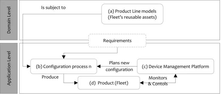
Figure 1: The DSPL Process
creation and use of domain models, to automate code generation [8][9]. Dynamic Software Product Line Engineering (DSPLE) is under the umbrella of MDE, as it uses models at runtime to address variability and context changes during system execution.
DSPL uses software product lines principles to build systems that can adapt to context fluctuation, new user requirements and variant QoS states. These principles include software reuse, variability modelling and management, and automatic product derivation.
We consider the DSPL paradigm the most fitting approach to provide autonomic scalable support for a fleet of connected devices, from design to execution [10]. First, DSPLs provide a systematic and non-restrictive way to deal with SASs [11], also they successfully realize the MAPE-K loop [12] as tested by Bencomo et al. in [13]. Besides, on the one hand, monitoring and controlling are the main activities for the fleet management. On the other hand, these same two activities are central tasks in DSPLs, which makes the paradigm a good fit for the self-adaptation of the fleet. Also, with regards to uncertainty, the quality of a product can be measured against user requirements by the mean of Goal-based approaches. Goal models can represent the system requirements at the domain level of (D)SPLs, in the form of variable reusable components. Furthermore, variability is a key challenge in the management of a fleet of connected things; it takes place at different levels. Static variability is concerned with similarities and variations between fleets, while dynamic variability is dealing with the runtime reconfiguration, and temporal variability, describes the
alterations of the three dimensions. Dealing with variability is by far the greatest asset of DSPL, since it adopts essential concepts from SPL [14].
2.3. Design principles
The first level in the process is the creation of assets. As described in Figure 1, a meticulous study of the domain in question helps define the qualities the system should satisfy, while specifying the variability and the variation points. The result of a domain study is the specification of the fleet’s requirements (a). The second level is the creation of the final product. The requirements of each customer are described in formal language. The selection of features is carried out accordingly, and then adjusted to fit the exact needs of the customer. Features are finally derived, linked, tested and deployed in order to instantiate the Product—the fleet (d).
DSPLE takes the SPL process one phase further. Each product is thoroughly monitored (c) to determine the structural or behavioural state that dissatisfies requirements. When these are no longer fulfilled, a new configuration is planned (b). This one achieves the optimal satisfaction of primary goals. Features are then re-selected, re-adjusted, re-derived and re-linked (re-tested and re-deployed) to create a new product—a new configuration for the fleet. This process is repeated whenever the system fails to fulfil requirements, in light of contextual change.
Do
m
ai
n
Le
ve
l
A
p
p
lic
ati
o
n
Le
ve
l
(a) Product Line models (Fleet’s reusable assets)
(d) Product (Fleet)
(c) Device Management Platform Requirements
(b) Configuration process n
Monitors & Contols Plans new
configuration Produce
Is subject to
EAI Endorsed Transactions
4
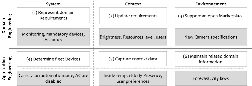
Figure 2: A DSPL three-dimensional Framework
From one engineering process to the other, the fleet’s three dimensions, the system, the context and the environment, have different designations, as described and illustrated in Figure 2. At the domain engineering level, each one of the concepts contributes to the creation of assets. With regards to the system (1), a domain expert thoroughly studies the domain in order to determine the functionalities the system should provide and qualities to comply with. In this sense, the system is where domains requirements are extracted, which are then translated to goals, features, components or assets. Context (2) is where the events that can arise after the deployment of the fleet are abstracted, in order to determine when a reconfiguration is needed. Environment (3) holds more generic information about domains and devices. It can contribute to the evolution and extensibility of the system by supporting an open Marketplace. This one could supply the system with new components, device specifications, documentation, and other related information.
At the application engineering level, deployment, monitoring and controlling aspects take place. In relation to the system (4), for each set of requirements, a product is derived. It reflects the nature of devices involved in the configuration, and their setup. Context (5) on the other hand deals with internal change, events and stakeholders that surround the system, and that have an impact on it. Devices are monitored in order to determine situations when reconfiguration is required. Sensed or calculated information, feedbacks, battery level, computational performance, network and data accessibility, and other characteristics are relevant. Devices that are not part of the system, but contribute to its activity are part of the context, user activity and logs also matter, the time and space of the fleet is also responsible of how it is configured. The environment (6), finally, is place to generic information about the surroundings of the system, that might, but still do not have an impact on the fulfilment of requirements. Devices around the fleet can be in this category, laws, rules or conditions constrained by a time or place are too, part of the environment. Monitoring the environment gives the platform proactive
qualities, this helps avoid waste of resources in unnecessary adaptations.
3. A Smart Building Motivational
Example
To cope with the challenges that IoT applications face, like heterogeneity, variability and resource constrained environments, the system should have the ability to adapt itself in order to continue offering the needed performance. This is illustrated through the following Smart Building example: The Forester’s family owns a summerhouse, one to which they only go on vacation. The house is equipped with devices that help secure and maintain it in their absence, and provide comfort and convenience in their presence. Some of the devices involved in this process work permanently, and others depend on the circumstances in the surroundings.
The fleet is composed of the following: To detect and monitor events and changes within or in the surroundings, a collection of sensors are installed around the building. They include smoke detectors and motion sensors, which should always stay active, and temperature sensors, fall
detectors and Light sensors which are only active when the house is occupied. To react to changes, various actuators were also deployed. They include sprinklers,
ACs and a noise canceling devices. Light that can be controlled manually or automatically, or by opening or closing curtains for natural light. The security is provided by an exterior camera, which can work permanently, or record when motion is detected. Water and electricity
consumption are also monitored using smart meters, and can be controlled thanks to the switch between the Mains
provider and the rainwater or battery bank, respectively for water and electricity consumption optimization. And, finally, a control panel is provided to administrators, on premise, locally in the house, or through the smartphone’s app.
Moreover, in order to serve the different needs of its users, under different circumstances, in a smart proactive
System Context Environnement
D
om
ai
n
E
n
g
in
e
e
ri
n
g
A
ppl
ic
ati
on
E
n
g
in
e
e
ri
n
g
(1) Represent domain
Requirements (2) Update requirements (3) Support an open Marketplace
(6) Maintain related domain information (5) Capture context data
(4) Determine fleet Devices Monitoring, mandatory devices,
Accuracy Brightness, Resources level, users New Camera specifications
Forecast, city laws Inside temp, elderly Presence,
user preferences Camera on automatic mode, AC are
disabled
EAI Endorsed Transactions
5
manner, the fleet should be self-adaptive. The following scenario can be considered:
a. The house is equipped with fall detection sensors, noise canceling devices and in-Room Cameras. They are not always needed, and should only be activated when the Grandmother’s smartphone is detected in the house, in order to monitor her activity, and guarantee her comfort.
b. If no one is in the house after coming back from vacation, the everyday features, responsible for adding comfort to the family, by automating certain tasks, are deactivated. Only maintenance and security features should be kept active in the fleet.
c. To preserve the overall consumption in the building, certain features can be deactivated when not needed, to avoid an overpriced bill.
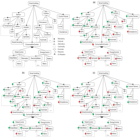
The fleet is considered as a DSPL. Each configuration of the fleet is a product that shares common characteristics with other configurations, but still answers the specific needs of the customer it serves. Figure 3 highlights examples of the various products that can be derived from the DSPL, which arise under the different circumstances described above.
4. Domain Engineering
Domain engineering (DE) lays the groundwork for engineering single software systems. At this level, the requirements of the fleet are defined in terms of common and variable features (devices and their respective configurations). The result of this phase is the dynamic product line, meaning all the possible configurations the fleet can take, along with the rules to manage arising changes in the environment. This section introduces the DE related models, and the nature of requirements that can be specified at this level, depending on the dimension they relate to.
4.1. Variability model
A Variability Model [15] is responsible for documenting and describing variability. It is an abstraction of the system’s requirements in the form of common and variable features. Variability Models can be represented in different forms: Feature models, goal models, decision models, variation points or in the form of constraints.
Variability models are a pertinent choice in the context of IoT applications, as they represent the (1) system dimension in our Framework. They are responsible for describing the various devices that compose the fleet, as well as their configurations (the available options, the activated modes, the embedded devices or sensors, and the parameters and values that are important for its functioning). For instance, the configuration of each device in the Smart Building fleet is commanded by the following constraints:
ID (Non) Functional Requirement
Req1
Sensors should always monitor motion and
smoke, and could monitor temperature and fall
in particular setups.
Req2 The AC can only function if the Temperature
Sensor is selected
Req3
The camera can record permanently, or it can be on hibernate mode and only be wakened when
motion is detected. A camera installed in the guest room can be activated under certain circumstances.
Req4
The lightning in the house can either be controlled manually through light switches, or automatically. Curtains can be selected, along with one of these modes to avoid unnecessary usage.
Req5 Consumption Control can be activated. In might include Water Control or Energy Control.
Req6
Controlling the water involves choosing a water source; it can be provided from the Mains or from the Rainwater reservoir. For a more meticulous monitoring, the water control can track the exact amount through a water meter.
Req7
Controlling the electricity involves choosing a power source; it can be provided from the Mains or from the home battery bank. For a more meticulous monitoring, the Electricity control can track the exact amount through an electricity meter.
Req8
The administrators can control the fleet through a local control panel or using their Smartphone Apps, or both.
Req9 The fleet should be energy efficient
Req10 The fleet should be efficient with water consumption
Req11 The fleet should provide accurate results
Table 1: Variability constraints
4.2. Context models
Context models [16] are central for building self-adaptive systems, as they characterize the status of the different entities that compose the PL. They are used to model the elements of the (2) context dimension of the Framework. Not only does a context model allow the acquisition and abstraction of context elements, but it also delignates the adaptation logic that links a context to its ideal configuration. Today, thanks to the insight that smart sensors bring about their surroundings, we can realistically imagine scenarios like starting a car when the conductor’s smartphone is close or preparing the conference room for a meeting by turning on the lights,
EAI Endorsed Transactions
6
opening the curtains, and lunching the appropriate presentation when it is in the agenda.
Context models are a combination of all context variables, which are abstractions over a part of the system’s context. The values of a context variable are monitored at runtimes, by reporting on events, by sensing change in the context, or by catching device exception.
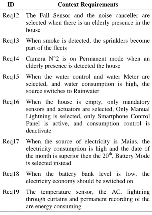
In the case of the Smart building fleet, several context elements have an impact on the final product. An example of context elements is presented in the following:
ID Context Requirements
Req12 The Fall Sensor and the noise canceller are selected when there is an elderly presence in the house
Req13 When smoke is detected, the sprinklers become part of the fleets
Req14 Camera N°2 is on Permanent mode when an elderly presence is detected the house
Req15 When the water control and water Meter are selected, and water consumption is high, the source switches to Rainwater
Req16 When the house is empty, only mandatory sensors and actuators are selected, Only Manual Lightning is selected, only Smartphone Control Panel is active, and consumption control is deactivate
Req17 When the source of electricity is Mains, the electricity consumption is high and the date of the month is superior then the 20th, Battery Mode is selected instead
Req18 When the battery bank level is low, the electricity economy should be switched on
Req19 The temperature sensor, the AC, lightning through curtains and permanent recording of the are energy consuming
Table 2: Context Constraints
Context models that include spatial and temporal constraints can be used to model the (3) environment dimension of our framework. Other models like prediction models and forecast models [17] are also relevant. In the case of the Smart building Example, Environment related information may include statements like: Recording a street view is forbidden or Water consumption should not succeed 400l per habitant in periods of drought.
4.3. Asset Marketplace
Services provided by the fleet are portrayed in the implementation model. They are represented as a collection of reusable programs that provide the functionalities described in the variability model.
Furthermore, in a fleet of connected objects, managed devices are unknown and unanticipated. Therefore, to allow the extensibility of the system, it should be possible to introduce new functions by adding components from the outside, through a secure regulated platform. Every operationalization is implemented through a collection of assets. They are reusable components that gather the logic for the implementations in the connected objects.
However, in order to properly fit in the framework, this view should provide the means to link the operationalization to a collection of assets, in order to guarantee the extensibility of the system. Different assets might correspond to different implementations of an operationalisation; different standards, different algorithms, or different languages. A developer’s open marketplace could host the various components responsible for enabling various services. And interfacing capabilities could link the modelled assets with their respective implementations.
5. Application Engineering
Application engineering (AE) starts with the elicitation of requirements for each customer in formal language. Features and components are selected accordingly. The list of components is readjusted in case it doesn’t correspond to the exact demands of the customer. The final components are derived, linked, tested and deployed in the form of a product, which can change if and when any change in the context occurs. This section introduces the AE related activities, depending on the dimension they relate to.
5.1. Configuration
The configuration process corresponds to the selection of features and their corresponding components, in accordance with the users’ requirements. The list of assets is readjusted in case it doesn’t correspond to the exact demands of the customer (by adding or suppressing some of the automatically selected features), then linked. The final components are derived; tested and deployed in the form of a product, which corresponds to the new configuration of the fleet.
5.2. Context Data
The context model is exploited at this level, along with a monitoring platform, which supervises the fleet, captures change that occurs in the surroundings of the devices, and analyzes it. Furthermore, it keeps track of the state and physical conditions of devices individually; if an unusual behavior, a contradiction, or an unhealthy pattern is observed, the context model coordinates with the variability model, in accordance with the constraints that bind then, to plan and execute a new set of configurations.
EAI Endorsed Transactions
7
Likewise, a user context model and a behavior monitor could be used to observe the actions of users, and learn their routines and patterns. This learning process could update the requirements at the application level to propose configurations that are more aligned with the realistic preferences of the user.
Provided as input to the model implementation, context data are the instances that context variables take under certain circumstances.
5.3. Environment Data
Unlike context data, which represent information that has a direct impact on the fulfillment of user’s requirements, environment data refers to information and knowledge related to the domain. It does not have a direct impact on the system at a specific time, but might bright insight in particular situations. It is important to grasp and implement such information to make use of it when necessary.
6. Model implementation
In the following section, we propose an implementation of the models described in the previous section, in the form of a declarative constraint program.
Each feature in the variability model is defined as a Boolean variable [18]. When selected in the final product, the value of the variable is 1, when it is not, the value is 0.
%--- Defining the reusable features
LRC = [SmartBuilding, Sensor, Smoke, Temperature1, Temperature2, Temperature3, Light, Motion1, Motion2, Fall, Actuator, AC1, AC2, AC3, NoiseCanceling, Sprinkler1, Sprinkler2, Sprinkler3, Lightning, Manual, Automatic, Curtains, Camera1, Camera2, Permanent, InMotion, Off, ControlPanel, Local, Smartphone, ConsumptionControl, WaterControl, WaterMeter, MainsWater, RainWater, EnergyControl, ElectricityMeter, MainsElectricity, Battery],
fd_domain(LRC, 0, 1),
The variables are constrained with expressions [19]; they translate the predicates expressed in Table 1. The collection of variables form a constraint satisfaction problem that can be solved, in order to determine the valuable valid configurations.
%--- Constraints on features %The root is always selected SmartBuilding #= 1,
%Defining the features related to the SmartBuilding SmartBuilding * 4 #= Sensor + Actuator + Lightning + ControlPanel,
SmartBuilding * 2 #>= Camera1 + Camera2, SmartBuilding #=< Camera1 + Camera2, SmartBuilding #>= ConsumptionControl, %Req5 %The subfeatures of Sensor
Sensor * 3 #= Smoke + Motion1 + Motion2, %Req1
Sensor *5 #>= Temperature1 + Temperature2 + Temperature3 + Fall + Light ,
%The subfeatures of Actuator
Actuator * 1 #=< Sprinkler1 + Sprinkler2 + Sprinkler3, Sprinkler1 + Sprinkler2 + Sprinkler3 #=< Actuator * 3, Actuator * 4 #>= AC1 + AC2 + AC3 + NoiseCanceling %The subfeatures of Lightning %Req4
Lightning #= Manual + Automatic, Lightning #>= Curtains,
%The subfeatures of Camera1
Camera1 #= Permanent + InMotion, %Req3 %The subfeatures of Camera2
Camera2 #= Permanent + InMotion, %Req3 Camera2 #>= Off,
%The subfeatures of ControlPanel %Req8 ControlPanel *2 #>= Local + Smartphone, ControlPanel #=< Local + Smartphone, %The subfeatures of ConsumptionControl
ConsumptionControl * 2 #>= Local + Smartphone, %Req5 %The subfeatures of WaterControl %Req6
WaterControl #= MainsWater + Rainwater, WaterControl #>= WaterMeter
%The subfeatures of EnergyControl %Req7 EnergyControl #= MainsElectricity + Battery, EnergyControl #>= ElectricityMeter
%The Traversal relations
(Rainwater #= 1 -> WaterMeter #= 1), (Battery #= 1 -> ElectricityMeter #= 1), (AC1 #= 1 -> Temperature1 #= 1 ; AC1 #= 0 ), (AC2 #= 1 -> Temperature2 #= 1 ; AC2 #= 0 ), (AC3 #= 1 -> Temperature3 #= 1 ; AC3 #= 0 ),
Non-functional requirements (NFR) are represented as variables that can take several values (from 0 to 4), each value represents a satisficing level, which corresponds to the importance of the NFR for the user.
%--- Non-Functional Requirements %Req9, 10, 11 LNFR = [Accuracy, EnergyEfficiency, WaterEfficiency], fd_domain(LNFR, 0, 4),
%--- Constraints on NFR
TotNFR #= Accuracy + EnergyEfficiency + WaterEfficiency;
Context and environment models are also translated to variables. Depending on the value they take during application engineering, they have various repercussions.
%--- Context Variables
LCtxt = [ElderlyPresence, SmokeDetected, OccupiedHouse, MainsElectricity],
fd_domain(LCtxt, 0, 1),
fd_domain(ElectricityConsumption, 0, 2), % 0 = low, 1 = normal, 2 = High
fd_domain(WaterConsumption, 0, 2), % % 0 = low, 1 = normal, 2 = High
fd_domain(BatteryLevel, 0, 1), % % 0 = low, 1 = normal
fd_domain(DayOfteMonth, 1, 31),
On the one hand, they can condition the selection of certain features, along with their effect on the realization of NFR.
EAI Endorsed Transactions
8 %--- Claims
LCl = [C1, C2, C3, C4], fd_domain(LCl, 0, 1),
%--- Constraints on Claims
%Effect of features and context values on EnergyEfficiency C1 #<=> (OccupiedHouse #= 1) #/\ (Temperature1 #==> EnergyEfficiency #=< 2) #/\ (Temperature2 #==> EnergyEfficiency #=< 2) #/\ (Temperature3 #==> EnergyEfficiency #=< 2) #/\ (AC1 #==> EnergyEfficiency #=< 0) #/\ (AC2 #==> EnergyEfficiency #=< 0) #/\ (AC3 #==> EnergyEfficiency #=< 0) #/\ (Permanent #==> EnergyEfficiency #=< 0) #/\ (Curtains #==> EnergyEfficiency #=< 3),
C2 #<=> (ElderlyPresence #= 1) #/\ (Light #==> EnergyEfficiency #=< 2) #/\ (NoiseCanceling #==> EnergyEfficiency #=< 1), %Req12 , %Req14
C3 #<=> (InMotion #==> EnergyEfficiency #=< 4) #/\ (Automatic #==> EnergyEfficiency #=< 2),
C4 #<=> (ElectricityConsumption #= 2) #/\ (DayOfteMonth #>= 19) #/\ (Battery #==> EnergyEfficiency #=< 4),
%Effect of features and context values on WaterEfficiency C5 #<=> (RainWater #==> WaterEfficiency #=< 1) #/\ (MainsWater #==> WaterEfficiency #=< 3), %Req17
%Effect of features and context values on Accuracy
C6 #<=> (OccupiedHouse #= 1) #/\ (Temperature1 #==> Accuracy #=< 4) #/\ (Temperature2 #==> Accuracy #=< 4) #/\ (Temperature3 #==> Accuracy #=< 4) #/\ (AC1 #==> Accuracy #=< 4) #/\ (AC2 #==> Accuracy #=< 4) #/\ (AC3 #==> Accuracy #=< 4) #/\ (Curtains #==> Accuracy #=< 1), C7 #<=> (ElderlyPresence #= 1) #/\ (Light #==> Accuracy #=< 2) #/\ (NoiseCanceling #==> Accuracy #=< 1),
C8 #<=> (InMotion #==> Accuracy #=< 1) #/\ (Permanent #==> Accuracy #=< 4),
C9 #<=> (WaterMeter #==> Accuracy #=< 3) #/\ (MainsWater #==> Accuracy #=< 3) #/\ (MainsElectricity #==> Accuracy #=< 3) #/\ (ElectricityMeter #==> Accuracy #=< 3) #/\ (Curtains #==> Accuracy #=< 1) #/\ (Automatic #==> Accuracy #=< 3),
TotC #= C1 + C2 + C3+ C4 + C5 + C6 + C7 + C8+ C9,
On the other hand, they define how the satisfaction of NFR is bound by context and environment conditions.
%--- SoftDependencies LSD = [SD1, SD2, SD3], fd_domain_bool(LSD),
%--- Constraints on SoftDependencies
SD1 #<=> (WaterConsumption #= 2 #==> WaterEfficiency #= 4),
SD2 #<=> (ElectricityConsumption #= 2 #/\ BatteryLevel #= 0) #==> EnergyEfficiency #= 4),
SD3 #<=> (ElectricityConsumption #= 2 #/\ WaterConsumption #= 2) #==> Accuracy #= 4),
TotSD #= SD1 + SD2 + SD3,
%Constraints on the ensemble: {Claims, NFR, SoftDependencies}
All #= TotC + TotSD + TotNFR.
Finally, after instantiating the context variables, and depending on the wishes of the user, which might be, for example, (i) any valid product, (ii) the best product, (iii)
the product that satisfies most the NFR Energy Efficiency, a configuration can be obtained by lunching a function that solves all the constraints, and proposes (i) a random result, (ii) the best result or (iii) the result for a
EnergyEfficiency=4.
7. Related Works
To face the growing complexity of IoT environments, several researchers have identified the need for Frameworks and architectures that support the management of fleets of cooperative devices, considering self-adaptation a core requirement. Inox [20] combines IoT and service architectures to provide enhanced application and service deployment capabilities. The architecture enables the service and network infrastructure with self-management capabilities. In [21], the authors propose an architecture, where agents collect data about protocol operations, measurement-based learning assess the optimality of the control parameter and if necessary, adaptation is realized by applying the new policies to agents. The Focale project [22] introduces an architecture for orchestrating the behavior of heterogeneous distributed resources. Data models support the derivation of different models from a core model, and ontologies reason about the change. The ACE model, proposed in the Cascadas Project [23], defines a agent-based architecture that enables service components to dynamically adapt their behavior based on their context. In [24], a cognitive management framework finds the optimal way to deliver an application in different contexts by enabling the reuse of virtual objects.
With the exception of the Focale Project, none of the above frameworks realize proactive adaptation. Furthermore, in the discussed architectures, no mechanism was proposed to validate the need for intelligent adaptation. Finally, variability is not considered a fundamental concern, thus not managed.
Several DSPL based architectures can also be found in the literature. In [25], a DSPL based architecture, combined with preference based reasoning, provides the necessary mechanisms for reasoning about change; this allows the realization of decentralized self-managed system. Gaia-PL [26] is an extension of the Gaia platform for the analysis and design of multi-agent systems in active spaces. A requirement specification pattern captures the behavior of a system in dynamic conditions, and reuses the software assets for future similar systems. In [27], the author proposes a multi-view blueprint architecture, a basis for future smart city projects, based on the SoaSPLE [28] framework for run-time variability management of service-oriented software product lines. Finally, authors in [29] propose a SPL based process for the development of connected devices, defined by the means of CVL, to provide reuse mechanisms for the development of a family of agents.
In contrast with the aforementioned (D)SPL based approaches, our framework introduces variability
EAI Endorsed Transactions
9
management at different stages of the process, as explained previously, including static (devices), dynamic (configurations) and time-bound (dimensions alterations) variability. None of the proposed SPL based approaches introduce the environment dimension, necessary for a smart proactive adaptation.
7.1. Conclusion and Future Work
The IoT paradigm enables advanced applications by interconnecting multiple devices that interact with their environment, and coordinate to provide the needed services. The smart city is one of the major targets of the IoT, as it gathers countless devices that constantly collect information, and thus can provide various cutting-edge benefits. However, the needs of end-users are divergent and the context conditions fluctuant. Therefore, supplying connected devices with the necessary mechanisms to answer the complex needs of each customer, and readjust their behaviour in the face of resource shortage, internet interruptions or service unavailability becomes essential.
Implementing fleets of connected devices as SASs is not completely new in research nor in industry, the design of such platforms however, remains problematic.
This paper proposes a framework to design adaptable applications for the IoT, in order to tackle the problem of dynamic variability. On the one hand, it takes into account the specificities of requirements for a fleet of IoT systems, which can be related to the system, the context or the environment. And, on the other hand, it follows the fundamentals of DSPLE; domain engineering and application engineering. A preliminary proof of concept Smart Building example was used to illustrate the requirements concerned by each dimension of the framework. And finally, a constraint program implements the example, in order to demonstrate how each model can be analysed and resolved.
Nonetheless, some of the framework’s main concepts are still not represented using the existing models. Prediction, behavioural learning, model auto-update, among other capabilities, are still not formulated.
REFAS [30], is a Goal-based modeling language implemented in Variamos [31]. It allows modeling requirements for self-adaptive software systems as DSPLs, from different points of view. As it implements most of the concepts to instantiate our framework, our future work includes extending its notation, with the missing concepts that allow the specification of all the needed requirements.
Acknowledgements.
This work was supported by the Moroccan « Ministère de l’Enseignement Supérieur, de la Recherche Scientifique et de la Formation des Cadres », by the « French Embassy in Morocco », and by the « Institut Français du Maroc ».
References
[1] G. H. Alférez, V. Pelechano, R. Mazo, C. Salinesi, and D. Diaz, “Dynamic adaptation of service compositions with variability models,” J. Syst. Softw., vol. 91, no. 1, pp. 24–47, 2014.
[2] M. K. Denko, L. T. Yang, and Y. Zhang, “Software Architecture-Based Self-Adaptation,” Auton. Comput. Netw., pp. 1–458, 2009.
[3] S. W. Cheng, D. Garlan, and B. Schmerl, “Evaluating the effectiveness of the rainbow self-adaptive system,”
Proc. 2009 ICSE Work. Softw. Eng. Adapt. Self-Managing Syst. SEAMS 2009, pp. 132–141, 2009.
[4] J. Kramer and J. Magee, “Self-Managed Systems : an Architectural Challenge,” in Future of Software Engineering, 2005.
[5] J. Filipe, A. Fred, and B. Sharp, “Toward a Self-Adaptive Multi-Agent System to Control Dynamic Processes,” Commun. Comput. Inf. Sci., vol. 129, 2011.
[6] E. P. S. Baumer, V. Khovanskaya, M. Matthews, L. Reynolds, V. Schwanda Sosik, and G. Gay, “Reviewing reflection: on the use of reflection in interactive system design,” Proc. 2014 Conf. Des. Interact. Syst. - DIS ’14, pp. 93–102, 2014.
[7] M. Mongiello, G. Boggia, and E. Di Sciascio, “ReIOS: Reflective Architecting in the Internet of Objects,”
Proc. 4th Int. Conf. Model. Eng. Softw. Dev., no. February, pp. 384–389, 2016.
[8] R. Rouvoy, P. Barone, Y. Ding, F. Eliassen, S. Hallsteinsen, J. Lorenzo, A. Mamelli, and U. Scholz, “MUSIC: Middleware support for self-adaptation in ubiquitous and service-oriented environments,” Lect. Notes Comput. Sci. (including Subser. Lect. Notes Artif. Intell. Lect. Notes Bioinformatics), vol. 5525 LNCS, pp. 164–182, 2009.
[9] R. Capilla, J. Bosch, P. Trinidad, A. Ruiz-Cortés, and M. Hinchey, “An overview of Dynamic Software Product Line architectures and techniques: Observations from research and industry,” J. Syst. Softw., vol. 91, no. 1, pp. 3–23, 2014.
[10] R. Mazo, C. Dumitrescu, C. Salinesi, and D. Diaz, “Recommendation heuristics for improving product line configuration processes,” Recomm. Syst. Softw. Eng., pp. 511–537, 2014.
[11] M. Hinchey, S. Park, and K. Schmid, “Building Dynamic Software Product Lines,” Computer (Long. Beach. Calif)., vol. 45, no. 10, pp. 22–26, 2012.
[12] IBM, “Autonomic Computing White Paper: An Architectural Blueprint for Autonomic Computing,”
IBM White Pap., no. June, p. 34, 2005.
[13] N. Bencomo, J. Lee, and S. Hallsteinsen, “How
EAI Endorsed Transactions
10 dynamic is your Dynamic Software Product Line?,”
Work. Dyn. Softw. Prod. Lines, 2010.
[14] C. Dumitrescu, R. Mazo, C. Salinesi, and A. Dauron, “Bridging the Gap Between Product Lines and Systems Engineering : An experience in Variability Management for Automotive ... Bridging the gap between product lines and systems engineering . An experience in variability management for automotive model based,” in 17th International Software Product Line Conference (SPLC), 2013, no. August.
[15] M. Sinnema and S. Deelstra, “Classifying variability modeling techniques,” Inf. Softw. Technol., vol. 49, no. 7, pp. 717–739, 2007.
[16] T. Strang and C. Linnhoff-Popien, “A Context Modeling Survey.”
[17] J. S. Armstrong, Principles of forecasting : a handbook for researchers and practitioners. Kluwer Academic, 2001.
[18] D. Benavides, P. Trinidad, and A. R. Cortés, “Using Constraint Programming to Reason on Feature Models.,” Seke, pp. 677–682, 2005.
[19] P. Sawyer, R. Mazo, D. Diaz, C. Salinesi, and D. Hughes, “Using Constraint Programming to Manage Configurations in Self-Adaptive Systems,” Computer (Long. Beach. Calif)., vol. 45, no. 10, pp. 56–63, Oct. 2012.
[20] S. Clayman and A. Galis, “INOX: A Managed Service Platform for Inter-Connected Smart Objects Stuart,”
Proc. Work. Internet Things Serv. Platforms - IoTSP ’11, pp. 1–8, 2011.
[21] A. Athreya, B. DeBruhl, and P. Tague, “Designing for Self-Configuration and Self-Adaptation in the Internet of Things,” Proc. 9th IEEE Int. Conf. Collab. Comput. Networking, Appl. Work., pp. 585–592, 2013.
[22] J. Strassner, N. Agoulmine, and E. Lehtihet, “FOCALE: A novel autonomic networking architecture,” Int. Trans. Syst. Sci. Appl. J., pp. 64–79, 2007.
[23] L. Baresi, A. Di Ferdinando, A. Manzalini, and F. Zambonelli., “The CASCADAS Framework for Autonomic Communications,” Auton. Commun., no. February 2017, pp. 1–374, 2009.
[24] P. Vlacheas, R. Giaffreda, V. Stavroulaki, D. Kelaidonis, V. Foteinos, G. Poulios, P. Demestichas, A. Somov, A. Biswas, and K. Moessner, “Enabling smart cities through a cognitive management framework for the internet of things,” IEEE Commun. Mag., vol. 51, no. 6, pp. 102–111, 2013.
[25] I. Ayala, J. M. Horcas, M. Amor, and L. Fuentes, “Using Models at Runtime to Adapt Self-managed Agents for the IoT,” Sensors, pp. 155–173, 2015.
[26] J. Dehlinger and R. R. Lutz, “Gaia-PL: A Product Line Engineering Approach for Efficiently Designing Multiagent Systems,” ACM Trans. Softw. Eng. Methodol., vol. 20, no. 4, pp. 17:1–17:27, 2011.
[27] M. Abu-Matar, “Towards a software defined reference architecture for smart city ecosystems,” 2016 IEEE Int. Smart Cities Conf., pp. 1–6, 2016.
[28] M. Abu-Matar and H. Gomaa, “An automated framework for variability management of service-oriented software product lines,” Proc. - 2013 IEEE 7th Int. Symp. Serv. Syst. Eng. SOSE 2013, pp. 260–267, 2013.
[29] I. Ayala, M. Amor, L. Fuentes, and J. Troya, “A Software Product Line Process to Develop Agents for the IoT,” Sensors, vol. 15, no. 7, pp. 15640–15660, Jul. 2015.
[30] J. C. Muñoz-Fernández, G. Tamura, M. Raúl, and C. Salinesi, “Towards a Requirements Specification Multi- View Framework for Self-Adaptive Systems,” Comput. Conf. (CLEI), 2014 XL Lat. Am., vol. 18, no. 2, pp. 1– 12, 2014.
[31] R. Mazo, C. Salinesi, D. Diaz, J. C. Muñoz-Fernández, L. Rincón, C. Salinesi, and G. Tamura, “VariaMos: An Extensible Tool for Engineering (Dynamic) Product Lines,” in Proceedings of the 24th International Conference on Advanced Information Systems Engineering (CAiSE Forum’12), 2015, no. June, pp. 374–379.
EAI Endorsed Transactions
11
Figure 3: Examples of the Smart building configurations Sensor Smart building Fall Temperature Smoke Motion Lighning Curtains Manual Automatic Actuator NoiseCanceling AC Control Pannel Local Smartphone WaterControl Rainwater WaterMeter Mains EnergyControl Battery ElectricityMeter Mains Camera Permanent In-motion ConsumptionControl Sprinkler 1..2 Off Requies 1..2 1..* 2..2 Light 1..* Requies Requies Excludes Sensor Smart building Fall Temperature Smoke Motion Lighning Curtains Manual Automatic Actuator NoiseCanceling AC Control Pannel Local Smartphone WaterControl Rainwater WaterMeter Mains EnergyControl Battery ElectricityMeter Mains Camera Permanent In-motion ConsumptionControl Sprinkler 1..2 Off Requies 1..2 1..* 2..2 Light 1..* Requies Requies Excludes Sensor Smart building Fall Temperature Smoke Motion Lighning Curtains Manual Automatic Actuator NoiseCanceling AC Control Pannel Local Smartphone WaterControl Rainwater WaterMeter Mains EnergyControl Battery ElectricityMeter Mains Camera Permanent In-motion ConsumptionControl Sprinkler 1..2 Off Requies 1..2 1..* 2..2 Light 1..* Requies Requies Excludes (a) (b) (c) Optional Alternative Cardinality Or-Relation i .. j
Requires Excludes Mandatory Sensor Smart building Fall Temperature Smoke Motion Lighning Curtains Manual Automatic Actuator NoiseCanceling AC Control Pannel Local Smartphone WaterControl Rainwater WaterMeter Mains EnergyControl Battery ElectricityMeter Mains Camera Permanent In-motion ConsumptionControl Sprinkler 1..2 Off Requies 1..2 1..* 2..2 Light 1..* Requies Requies Excludes
EAI Endorsed Transactions