http://www.sciencepublishinggroup.com/j/ajn doi: 10.11648/j.ajn.20170303.13
Optimization of Optical Nanoantenna Based on Structures
Chiral Photonic Crystal
Mezache Zinelabiddine, Seghaouil Samir, Chaibi Walid, Benabdelaziz Fatiha
Department of Electronic, University of Brothers’ Mentouri Constantine 1, Constantine, Algeria
Email address:
zinemezaache@yahoo.fr (M. Zinelabiddine)
To cite this article:
Mezache Zinelabiddine, Seghaouil Samir, Chaibi Walid, Benabdelaziz Fatiha. Optimization of Optical Nanoantenna Based on Structures Chiral Photonic Crystal. American Journal of Nanosciences. Vol. 3, No. 3, 2017, pp. 47-52. doi: 10.11648/j.ajn.20170303.13
Received: May 11, 2017; Accepted: July 5, 2017; Published: August 16, 2017
Abstract:
A novel Optical nanoantenna based on chiral photonic crystals is studied via numerical simulation under environment COMSOL Multiphysics 5.0. We have shown new model of optical nanoantenna. Where this miniaturized antenna has great potential application in biomedical and nanotechnologies. Numerical results are given and discussed to confirm these characteristics.Keywords:
Chiral Photonic Crystals, Optical Nanoantennas, Radiation Diagram1. Introduction
From the first radio to the most advanced mobile phones, wireless telecommunications were based on the use of antennas emitting or receiving radio waves. We propose here to transpose the concept of antenna to the scale of the optics of the visible. In this case, the reduction of the scales imposes the realization of submicron structures, baptized nanoantennes [1-5]. The latter aim here to act as a relay between the near - field spaces (nano - sources and nano-collectors) and far - field (propagating waves) for the localized emission or reception of light. Our objective is to find the geometries of nanoantennes allowing to optimize their emission or reception yields or to attribute to them selectivity with respect to the vectorial electromagnetic field that they radiate or that they collect (polarizing properties, Sensitivity to the electric or magnetic field, etc).
In this paper, we will study an optical nanoantenne based on dielectric materials, using a 2D CPC chiral photonic crystal structure [5-11], simulation allowing the plots of the radiation patterns of the adopted model. Then, we will introduce some modifications on the physical parameters of this structure in order to visualize its energy in emission, while evaluating its characteristic parameters and able to determine them; and thus compare the results obtained.
This optical nanoantenna will be intended for use in the biomedical field, precisely in the spectroscopy of single molecules, based on the control of exaltation by molecular
fluorescence.
At present, nano-antennas are used in near-field and high-resolution biomedical microscopy; As well as in the detection of viruses and bacteria at the cellular level. There are other potential applications that we believe to be equally promising, including solar cells [12], and molecular sensors in biomedical [12]. Also, in optical communication, and also in the realization of sensors for applications to hyperthermic therapy of skin neoplasms, which are currently under study.
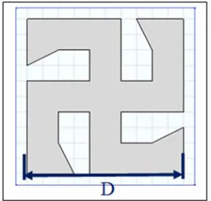
2. Construction of the Model
In order to model our optical nanoantennas with the modified CPC structure (Figure. 1), we chose in COMSOL Multiphysics 5.0 the electromagnetic wave domain, Frequency Domain (ewfd) in Comsol. We have placed it in a parabolic environment, linearly polarized in TE mode, and generating wave propagation along the y-axis.
The dielectric CPC structure of the titanium dioxide TiO2
with a refractive index ng = 2.909 is surrounded by an air
layer of refractive index n = 1, itself surrounded by a PLM
layer "perfectly absorbing layer". The model is symmetric along the y-axis.
Figure 2. Model of the optical nanoantenne.
The network and the study The mesh
Normal mesh configured by the user. a. Size for the CPC structure. b.Free Tetrahedr al for the air layer.
c. Swept for the PML layer The field of study
a. Frequencies from 400THz to 750THz b. Stationary Study
c. The number of iterations in the calculations equals 10e-4
Figure 3. Representation in a distant electric field (V / m), of the optical nanoantenne.
Figure 3 illustrates the energy nature of the far-field electric field radiation of the nano optical antenna. In this figure, the evolution of the propagation of electrical energy
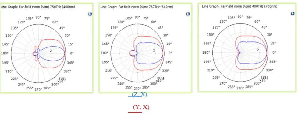
For F1 = 750THz (b) For F2 = 467THz (c) For F3 = 400THz
Figure 4. Radiation diagram for D = 250nm.
In this stage of our work, results, relating to far-field radiation patterns of the antenna Figure 1, interesting and diverse were obtained. They consisted of diagrams, transmitted at frequency 750THZ, showing some parasites, with a clearly directed main lobe, according to the plane (Z, X), figure (4), a more spread directional lobe according to the plane (Y, X) (4). At the frequency 467THZ, the lobes along the planes (Z, X) and (Y, X) are less directional, but more spread, with less parasites. The third case treated diagrams transmitted at frequency 400THZ, the lobes are also spread, but without any presence of harmful parasites. All these emission cases of the treated antenna remain destined each for specific applications.
3. Study of the Geometric Influence on
the Radiation Patterns
The size of the structure can also be modified to see how
the absorption / transmission depend on the geometry. We vary the dimension D of the structure of 150nm, 250nm, 350nm, 450n to study the influence of D on the efficiency of radiation, and the directivity of the optical nanoantenne.
Figure 5. Structure of the modified cell of dimension D.
Figure 7. Represents the geometric change in dimension =150nm.
Figure 8. Represents the geometric change in dimension D = 250nm.
Figure 9. Represents the geometric change in dimension D = 400n.
The variations of the dimension D of the modified cell (5), depending on the values: 100 nm, 150 nm, 250 nm, 400 nm, have a slight influence on the radiation patterns.
4. Study of the Influence of a Dielectric
Layer Around the Structure on the
Radiation Patterns
The addition of a dielectric layer of silicon oxide, with a refractive index nh = 1.7, surrounding the structure studied,
with a dimension D = 250 nm, has an influence on the emission of the nano antenna and in particular its directivity.
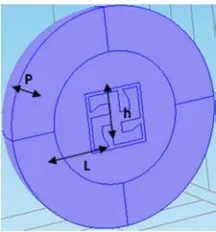
Figure 10. Structure of the modified cell of dimension D = 250 nm placed inside a cubic dielectric enclosure of dimensions Length L = 300 nm height h = 300 nm P = 300 nm depth.
(a) For F1 = 750THz (b) For F2 = 467THz (c) For F3 = 400THz Figure 11. Radiation diagram for D = 250nm.
A complementary modification was also introduced on the structure of the modified cell of dimension D = 250 nm, which is its location inside a cubic dielectric enclosure. Significant and diverse results, other than those obtained previously, have been obtained, relating to far-field radiation patterns of the nanoantennas Figure 10, They consisted of diagrams, transmitted at the frequency 750THZ, presenting some parasites, with main lobe (Z, X), figure 11, and a more spread lobe, according to the plane (Y, X), figure 11. At the frequency 467THZ, the lobes along the planes (Z, X) and (Y, X) are more spread with presence of parasites essentially in the plane (Z, X). The third case treated of the diagrams transmitted at frequency 400THZ, the lobes are also spread, with some harmful parasites only in the plane (Z, X). All these emission cases of the treated antenna remain destined each for specific applications.
5. Conclusion
The radiation patterns were plotted by the results obtained from the second COMSOL simulation program of optical nanoantennas. It should be noted that the consideration of geometrically complex CPC nanostructures will make it
possible to make new studies and achievements in nanotechnology.
Our perspective on nanophotonics will be the study of physical properties for other types of optical antennas, and other applications, for example in telecommunication and optical detection in biology. On the other hand, the development of collaborations with chemists and biologists is necessary, for possible biophotonic applications of optical nanoantennes.
References
[1] Mark W. Knight, Heidar Sobhani, Peter Nordlander, and Naomi J. Halas. Photodetection with active optical antennas. Science, 332: 702–704, 2011.
[2] A. E. Krasnok, I. S. Maksymov, A. I. Denisyuk, P. A. Belov, A. E. Miroshnichenko, C. R. Simovski, and Yu. S. Kivshar. Optical nanoantennas. Phys.-Usp., 56: 539, 2013.
[4] Yifat, Y., Ackerman, M., & Guyot-Sionnest, P. Mid-IR colloidal quantum dot detectors enhanced by optical nano-antennas. Applied Physics Letters, 110(4), 041106. (2017).
[5] Fischer, I. A., Augel, L., Kropp, T., Jitpakdeebodin, S., Franz, N., Oliveira, F., & Schulze, J. Ge-on-Si PIN-photodetectors with Al nanoantennas: The effect of nanoantenna size on light scattering into waveguide modes. Applied Physics Letters, 108(7), 071108. (2016).
[6] S. Noda, M. Fujita, and T. Asano, “Spontaneous-emission control by photonic crystals and nanocavities,” Nature Photon. 1, 449–458 (2007).
[7] H. Altug, D. Englund, and J. Vučković, “Ultrafast photonic crystal nanocavity laser,” Nature Phys. 2, 484-488 (2006).
[8] Benfeng Bai, Yuri Svirko, “Optical activity in planar chiral metamaterials: Theoretical study” physical review A 76, 023811 (2007).
[9] M. Thiel, G. von Freymann, and M. Wegener, “Layer-by-layer three-dimensional chiral photonic crystals,” Opt. Lett. 32, 2547-2549 (2007).
[10] M. Thiel, M. Hermatschweiler, M. Wegener, and G. von Freymann, “Thin-film polarizer based on aonedimensional– three-dimensional–one-dimensional photonic crystal heterostructure,” Appl. Phys. Lett. 91, 123515 (2007).
[11] Tun Cao, 1, Lei Zhang Strongly tunable circular dichroism in gammadion chiral phase-change metamaterials’’ Received 5 Aug 2013; published 6 Nov 2013 Vol. 21, No. 23 | DOI: 10.1364/OE.21.027841 | OPTICS EXPRESS 27841.