4261
A Real Time Implementation Of Fault Detection
Strategy In Dc Microgrid Using Internet Of Things
Albert Alexander.S, Manojkumar.K, Balaji.M, Manojkumar.S, Usharani.S
Abstract: One of the rising trends in the usage of microgrid with the non-conventional energy sources compose a recent type of facility that belongs to the intensive idea and can become the tremendous a part of the power system developme nt. It is conceited that existing grid evolution towards the micro grid can emerge as a system of organically integrated intelligent grids having all encompassing visibility with command and management functions distributed across the levels. In order to guard the microgrid, monitoring comes as a biggest requirement in national and international importance. Presently, the protection of the microgrid is done by several ways. This paper f ocuses on preventing harm to microgrid by detecting the faults happen within the system through an Internet of Things (IoT) based network so as to monitor it remotely. The proposed strategy will detect the faults like over voltage, over current, and overheating of the system. An IoT based technology is adopted to display, monitor, detect and diagnose the whole system even at the remote location through web server and mobile app. It uses the sensor node IoT to detect the faults in microgrid. From the properties and behaviors of the methodology, this paper conjointly highlights the feasibleness and future improvement of self healing DC microgrid.
Keywords: Internet of Things, Microgrid, Monitoring, Management, Power system faults, Protection of sources, Real time.
————————————————————
1
INTRODUCTION
Microgrid, operative in either grid-connected mode or islanded mode, enable native integration of energy generation, distribution, and storage at the consumer level for higher installation potency and management of demand. To maintain the stable operation of microgrid, phasor states of each microgrid and also the Area Electric Power System (AEPS) to that the microgrid connected, including frequency, phase angle, and voltage magnitude, ought to be monitored endlessly, particularly throughout the transition between two operation modes, i.e., resynchronization and islanding method. It consists of many elements comprises of solar panels, inverter, battery and different electrical accessories to line up an operating system. A microgrid grid with local profuse renewable energy sources facilitates small communities to take control of their energy use and diminish their carbon footprint through a brand new and innovative manner of generating and managing electricity. Although there is a raise in use of microgrid, its protection is not clear. So as to provide protection to microgrid, observation of PV system comes as a biggest importance in national and international state of affairs. A distributed energy sources is predicted to provide specific amount of power monthly. If the output is not of course, then there is also some faults within thesystem. This will be known given that the parameters were closely monitored.
Additionally its performance goes down once it is not supervised sporadically. Therefore observation unit becomesan inevitable part during a microgrid system. It has to monitor the amendment in multiple parameters of the grid that adversely affects its performance directly or indirectly. These parameters facilitate the user to determine its performance beside fault detection and real time observation. It additionally facilitates preventive maintenance and historical analysis ofsystem. Since most of them area unit put in inaccessible locations refined systems for observe the plants remotely area unit required. This will be with efficiency done by a wise observation and management unit with the assistance of Internet of Things technology (IoT) web based interfaces. This facilitate preventive maintenance, fault detection, historical analysis of the microgrid additionally to real time observation. Supervisory Control and DataAcquisition (SCADA) is used earlier to spot faults within the PV system. Enhancement, performance improvement and preventive maintenance of solar power plant is carried out by implementing Operation & Maintenance (O&M) activities with aid of exploitationprognostic analytics and SCADA. With the assistance of web (cloud) together with IoT devices, operation and maintenance, the preventive maintenance will be improved extensively. Several industries in India are working towards increasing the performance pertaining to quantitative relation of solar power plants in giant scale. In their efforts a comparative study is carried out to boost the performance of solar power plants through IoT and predictive analytics [1]. Wireless SensorNetwork (WSN) system, a power supply capable of gathering energy datacould be terribly crucial element consideringWSN normally installed in an exceedingly remote area far from the utility grid. The development of effective and efficient power supply continues to becurrent areas of research as a result ofsensing element node works incessantly in real time. The number of sensing element node is additionallythe explanation of why its power supplyshould be as effective and efficient as attainable, thereforecomparatively lower its value. This paper discusses a system to monitor the performance of photovoltaic power supply from sensing element node in an exceedingly WSN system. The intended parameters are ————————————————
Albert Alexander is currently working as an Associate Professor, Department of Electrical and Electronics Engineering, Kongu
Engineering College, Erode, TamilNadu,
IndiaEmail:[email protected]
Manojkumar.K, Balaji.M, Manojkumar.S, Usharani.Sare all currently pursuing bachelor degree program in Electrical and Electronics Engineering, Kongu Engineering College, Erode, TamilNadu, India
Email:[email protected], [email protected],
4262 temperature, irradiance, current, and voltage. The system is
divided into three main blocks such as client, server and communication system. The client has sensors, RTC, local display, backup data logger, and microcontroller. The communication devices are radio frequency module, Xbee. The server is computer software developed using LABView software [2]. Albert Alexander Stonier identified the various faults occurring in Photo voltaic systems using an artificial neural network which is an intelligent-based fault tolerant system for a solar photovoltaic (PV) inverter. Artificial neural network based controller is used to monitor, detect, and diagnose the faults in solar PV panels, battery, semiconductor switches, and inverters. The cascaded multilevel inverter is connected across the combination of solar PV panel and battery for DC–AC conversion. The major advantage of the topology is that it can deliver power from source to the load even under fault and partial shaded conditions. The paper also reviews on various faults in the solar PV energy conversion process and provides suitable solutions for each circumstance. Simulations are undertaken and experimental investigation is carried out for a 3 kWp solar PV system. The results have proven that the system is capable to deliver power in spite of faulty environments [3]. Farihah Shariff proposed the monitoring end composed of PV module; data acquisition device and GSM modem 1 while the remote PC end composed of GSM modem 2 and remote PC. PV module is monitored using data acquisition device. Data acquisition device consists of sensors, Real Time Clock (RTC) chip, and Liquid Crystal Display (LCD) and microcontroller unit. Microcontroller will collect all the data from sensors in five minutes interval time. GSM modem 1 will stored the received data and transmit it in short messages (SMS) to GSM modem 2. The second modem is connected to remote pc. The received data will be filtered and categorized before saved to excel file [4]. Swathika developed a Central Protection Centre (CPC) whose functions include: continuous microgrid monitoring, fault occurrence identification and faulted branch identification. The proposed Prims aided Dijkstras algorithm is continuously executed at CPC, which facilitates current topology identification and shortest path identification between faulted point and nearest operating source in microgrid. The algorithm aids the CPC in adaptively altering the relay settings in the shortest path based on their selectivity levels and hence attains fault clearance in less time with minimum network disconnection. The algorithm is effectively tested and validated on the reconfigurable IEEE 21-bus and standard 40-bus microgrid networks. From the results it is evident that the algorithm is capable of clearing several faults in the microgrid network continuously, it maybe conveniently extended to larger microgrid systems [5]. Mahinda presented the RL feed forward and flux-charge model feedback algorithms for protecting utility-interfaced microgrids from large line currents during utility-voltage sags. The RL algorithm functions by controlling a series inverter, connected between the micro- and utility grids, to insert a large virtual RL impedance along the distribution feeder to limit the line currents and damp transient oscillations with a finite amount of active power circulating through the series (and shunt) inverter. In contrast, the alternative flux-charge algorithm inserts only virtual inductive impedance with zero active power absorption and relies on its closed-loop-control tuning to damp transient oscillations [6]. Meena Agrawal
4263 intuitively their control/operational concepts were based on
scaled-down and simplified versions of control/operational concepts of large power systems. It also highlighted the main differences between microgrids and large power systems and on that basis advocates for a fresh approach to the development of control and operational concepts for micro grids [12]. Meliopoulos et. al., described a comprehensive approach for a smart grid implementation on a distribution system. The basic objective is that the infrastructure should enable all the desirable functions of optimizing the operation of the distribution feeder for maximum benefit to utilities and customers alike. These goals are achievable only via a system that will enable accurate and frequent monitoring of the distribution system. The monitoring function extends to the customer and includes monitoring and control of customer resources. A requirement placed on the proposed infrastructure is that the customer should not be inconvenienced. The scheme achieves the goals of the smart grid with minimal or no inconvenience to the customer. Implementation of this scheme will require the development of low cost meters [13]. Jiang proposed novel double-layer coordinated control approach for microgrid energy management was proposed in this paper. The proposed approach emphasizes on the difference of grid-connected mode and stand-alone mode, and has good convergence in either mode. The approach allows the microgrid to operate economically, safely and stably [14].
2.
DRAWBACKS
OF
EXISTING
SYSTEMS
Based on the extensive literature survey cited above, the existing methods of fault detection of DC micro grids possess the following drawbacks:
High operation and maintenance cost which restrict the development of monitoring system and ultimately hinder the process of efficient generation monitoring in real time
Remote Monitoring system using traditional methods like Data Logging are complex compared to IoT based system
The intermediate current injection from the Distributed Energy Resources, conventional coordination of over current relay is not possible (fault current which is in bidirectional)
3.
MICROGRID
Microgrid are able to be connected to the utility grid to buy power from the grid or sell power back to the grid as conditions dictate. Microgrid will be designed to work ―islanded‖ once the utility grid is not accessible. Microgrid with renewable energy sources compose a brand new type of an power system, that belongs to the broader concept of smart grids, and are getting an remarkable part of the power system organizations. It is envisioned, in the not too distant future, that existing grid evolution towards the smart grid can emerge as a system of organically integrated intelligent. Microgrid having all encompassing visibility with command-and-control functions distributed across the levels. On the other hand microgrid are proving to be a perfect solution to rural electrification, electrical power service to communities with lean populations ranging up to five hundred households besides it’s very well use in industrial parks, commercial,
institutional campus etc. A Microgrid with local profuse renewable energy sources facilitate small communities to take control of their energy use and diminish their carbon footprint through a new and innovative manner of generating and managing electricity. Figure 1 shows the forecast of microgrid world market which need to be achieved by 2023.
Fig.1. Market of Microgrid over the World
The rapid development of economy has led to an rise in energy crisis and environmental pollution. So, maximum utilization of renewable energy resources is in hour of need. There is an enormous quantity of assorted renewable energy resources that are available in India. In the present scenario, microgrid is one of the alternatives for electricity generation. It will satisfy the customers load demand at optimum price by reducing the grid congestion. The main objective of the projected work is to develop a cost efficient microgrid monitoring system that monitors, detects and displays varied parameters of the grid systems installed at remote locations using internet based interfaces (i.e. IoT). The sensors connected to the raspberry pi at one end and at another end of the sensors connected to the microgrid. The analog signals are converted into digital signals by using Arduino Nano. The digital signals are sending to the raspberry pi and the data are shown in Thingspeak app/ web. Finally to make developed system as a product (IoT) to monitor, display, fault detection in a remote or rural atmosphere to confirm the continuity of the supply from microgrid. The demand for microgrid is on an increase as they permit consumers and developers to satisfy the environmental objectives by using renewable energy in the form of power generation source. In line with this, governments of several nations are taking initiatives to establish bio power, solar and wind energy farms. Apart from this, countries like US have enforced regulations like the Clean Power Plan (CPP) rule that are aimed towards reducing carbon dioxide gas emissions.
4.
METHODOLOGY
4264 sensor. The data will collected and sent to a web server
through a controller (i.e.) Raspberry pi. The parameters were monitored continuously, where the threshold value of the quantity is violated, then the system indicates the occurrence of fault in the microgrid. In extension, we can send an alert message/mail to the person and type of fault also be mentioned in it. The block diagram of micro grid faults detection is shown in Figure 2 . A three layered IoT protocol design starting with perception layer (Layer 1) at the bottom which comprises of current sensor, voltage sensor and temperature sensor to collect various parameters and also fault type be identified by using raspberry pi (i.e. controller). Layer 2 (cloud) as envisaged is a network layers where the data thus collected processed. This information are finally printed in a web page which can also be accessed through a mobile app/web server which forms the final layer of the system depicted as application layer (Layer3). By the assistance of IoT, monitoring frequency may be of every day, and the system is able to report the result daily, monthly, or yearly as desired. The fault can be cleared within less time than the conventional protection methods.
Fig.2. Schematic Diagram
The solar panel is connected to battery and sensors. Here the voltage and current sensors are used to measure the voltage and current output of the solar panel. Arduino is used as Analog to Digital Converter for the conversion of analog signal to digital signal. The output from the Arduino is fed to Raspberry pi is used to connect to the web server. Photovoltaic solar panels absorb sunlight as a source of energy to generate electricity. A photovoltaic (PV) module is a packaged, connected assembly of typically 6x10 photovoltaic solar cells. Photovoltaic modules constitute the photovoltaic array of a photovoltaic system that generates and supplies solar electricity in commercial and residential applications. Each module is rated by its DC output power under standard test conditions (STC), and typically ranges from 100 to 365 Watts (W).The arrangement of solar panel is shown in Figure 3.
Fig.3. Arrangement of Solar Cells in a Solar Panel
Voltage sensor as shown in Figure 4 is symbolically represents a voltage divider circuit used to detect the voltage in the range of DC 0-25V. The voltage input to the sensor will be in the range of DC 0-25V. It has an analog resolution of 0.00489V.
Fig.4. Voltage sensor
The pin configuration the voltage sensor is shown in Figure 5. It has VCC which is the positive terminal of the voltage to be measured (0-25V),GND is a negative terminal of the voltage to be measured,S is an analog input of Arduino, (+) is Not connected (N/C) and (–) is GND of Arduino.
Fig.5. Pin Config. of Voltage sensor
ACS712 shown in Figure 6 is a fully integrated, Hall Effect based linear current sensor with 2.1 kV RMS voltage isolation and a low resistance current conductor.
4265 The pin configuration of the current sensor is shown in Figure
7. It has IP+ which is the positive terminal of the current to be measured (0-30 A),IP- is a negative terminal of the current to be measured,OUT is an analog input of Arduino, VCC is 5V and GND is Ground of Arduino.
Fig.7. Pin Config. of ACS712
The LM35 series (shown in Figure 8) is a precision integrated-circuit temperature sensing device with an output voltage linearly proportional to the centigrade temperature. As the LM35 device draws only 60 μA from the supply, it has very low self- heating of less than 0.1°C in still air. The LM35 device is rated to operate over a −55°C to 150°C temperature range, while the LM35C device is rated for a −40°C to 110°C range (−10° with improved accuracy).
Fig.8. Temperature Sensor – LM35
The Arduino Nano is a small, complete, and breadboard-friendly board based on the ATmega328 (Arduino Nano 3.0) or ATmega168 (Arduino Nano 2.x) as shown in Figure 9.
Fig.9. Arduino Nano
The pin configuration of the Arduino Nano is shown in Figure 10. The Analog pins are from A1 to A7 and the digital pins are from D2 to D12.
Fig.10. Pin Config. of Arduino Nano
The processor of Raspberry pi 3+ is Broadcom BCM2837B0, Cortex-A53 64-bit, SoC at 1.4 GHz, and memory is 1 GB
LPDDR2 SDRAM. The powerful feature of the Raspberry pi is the row GPIO pins along the top edge of the board. Any GPIO pin can be designated as input or output pin used for a wide range of purposes. The pin configuration of the Raspberry pi is shown in Figure 11.
Fig.11.Pin Config. of Raspberry pi
5.HARDWARE
IMPLEMENTATION
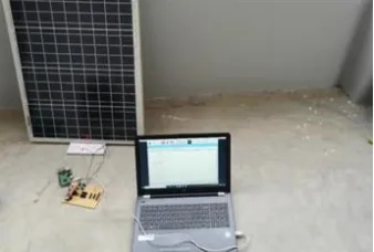
The solar panel is connected to the sensors in order to measure temperature, current and voltage. The output of the sensors is given to the Arduino Nano. Arduino fed output signal is fed to the Raspberry pi. The 5V supply will be provided to the Arduino Nano and Raspberry pi. The complete hardware setup is shown in Figure 12.
Fig. 12. Hardware Implementation
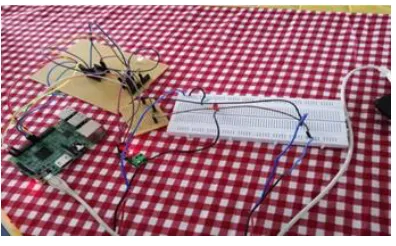
The python program shown in Figure 13 will be executed in the VNC server. It displays the data such as current, voltage from the solar panel which is connected to microgrid. The experimental connection is shown in Figure 14. The results can be accessed through mobile application as shown in Figure 15 and the results are depicted in Figure 16.
4266 Fig.14. Hardware Connection
Fig.15. Access data through Mobile phone
Fig. 16. Results
In comparison with the proposed IoT based system, the other systems are very complex, high cost and sizeable. A provision of advance remotely manage the solar photovoltaic panels of various operations like remote shut down, remote management is to be incorporate with this technique later.
6.CONCLUSION
Use of IoT for monitoring of a microgrid is a vital step as day by day renewable energy sources have getting integrated into utility grid. Thus automation and intellectualization of solar power plant monitoringcan enhance future deciding process for large scale solar power plant and grid integration of such plants. In this work we proposed an IoT based remote monitoring system for solar power plant, the approach is studied, implemented and successfully achieved the remote transmission of data to a server for supervision. The conditional threshold value is set to detect the fault occurrence in the system. The short circuit faults, earth fault and faults due to lightning etc. IoT based remote monitoringcan improve energy efficiency of the system by making use of low power consuming advanced wireless
modules thereby reducing the carbon footprint. Web Console based interface canconsiderablyreduce time of manual supervision and aid in theprocess of planning task of plant management.
7.ACKNOWLEDGEMENT
The authors acknowledge and thank the Department of Science and Technology (Government of India) for sanctioning the research grant for the project titled, ―DESIGN AND DEVELOPMENT OF SMART GRID ARCHITECTURE WITH SELF HEALING CAPABILITY USING INTELLIGENT CONTROL TECHNIQUES - A Smart City Perspective‖ (Ref.No. CRD/2018/000075) under AISTIC Scheme for completing this work.
8.REFERENCE
[1] Shahida Begum, Reshma Banu, Ali Ahamed, and B. D.Parameshachari ―A Comparative Study on Improving the Performance of Solar Power Plants Through IoT and Predictive Data Analytics,‖ 2016 International Conference on Electrical,Electronics, Communication, Computer and Optimization Techniques (ICEECCOT), 2016 IEEE Conference
[2]
Albert Alexander Stonier and Brad Lehman,
―An Intelligent Based Fault Tolerant System
for
Solar-Fed
Cascaded
Multilevel
Inverters,‖IEEE Transactions on Energy
Conversion on 2017
[3]
F.Shariff, N.A.Rahim, and H. W. Ping,
―Photovoltaic Remote Monitoring System
Based on GSM,‖ Clean Energy and
Technology (CEAT), 2013 IEEE Conference
on, 2013, pp. 379-383
[4]
O.V.G. Swathika, and S. Hemamalini,
―Prims-Aided
Dijkstra
Algorithm
for
Adaptive
Protection in Microgrids,‖ IEEE Journal of
Emerging and Selected Topics in Power
Electronics ( Volume: 4 , Issue: 4 , Dec. 2016)
[5]
D. Mahinda Vilathgamuwa, Senior Member,
IEEE, Poh Chiang Loh, Member, IEEE, and
Yunwei Li, Member, IEEE, ―Protection of
Microgrids During Utility Voltage Sags,‖ IEEE
Transactions on Industrial Electronics (
Volume: 53 , Issue: 5 , Oct. 2006 )
[6]
Ms. Meena Agrawal, Dr. Arvind Mittal, ―
Parameter Logging & Remote Monitoring for
Microgrid Demonstration Project,‖ 2014
Innovative Applications of Computational
Intelligence on Power, Energy and Controls
with their impact on Humanity (CIPECH),
published in IEEE on 2016
[7]
Haoyang Lu, Lingwei Zhan, Yilu Liu and Wei
Gao, ―A Microgrid Monitoring System Over
Mobile Platforms,‖ IEEE Transactions on
Smart Grid ( Volume: 8 ,Issue: 2, March
2017
4267