OPTIMIZATION OF GEOMETRIC PARAMETERS OF HARD METAL MICRO DRILS
TO INCREASE TOOL LIFE AND PERFORMANCE OF DRILLING PACKAGE OF
PRINTED CIRCUIT BOARDS
Doctor of science, Prof., Turmanidze R.1, Senior laboratory Bachanadze V.2, Undergraduate student Popkhadze G.3 Faculty of Transportation and MechanicalEngineering1, 2, 3 –Georgian Technical University, Tbilisi, Georgia, [email protected]
Abstract: In the presented work investigated the changes of power characteristics of deep drilling package of printed circuit board’s hard
metal micro drills depending on the drilling depth, cutting data and geometry of the drill. In particular studied the nature of changes in axial efforts and torque depending on the drilling depth drill with different inclinations of the spiral grooves using specially designed highly sensitive devices, enabling direct measurement method. Based on the analysis of the results of the study, changes in the geometry of existing standard drills. Proposed new construction of micro drills vary-angle spiral grooves in such a way that the angle is the maximum value at the top of the drill and uniformly decreases towards the end of the working parts. The drills are manufactured with different inclinations of the spiral grooves. Based on the experiments of them chosen more for its near standing power rates to the standard drill bit and its comparative test with a standard drill bit, bringing them up to the breakage, thanks to which the proven advantages of drills new design. Taking into account the results of the experiments proposed drill elongated structures to improve performance by increasing the processing drilling depth and accordingly the number of plates in the package of printed circuit boards.
Keywords: DRILL, GRADIENT OF SPIRAL GROOVE, VARIABLE ANGLE, DEVICE.
1.
Introduction
It is impossible to imagine modern equipment without electronic knots, starting from household and ending with space equipment. Printed circuit board’s production, basic parts of electronic equipment associated with drilling process vast quantities of small diameter holes (about 1mm or less). Carry out drilling of micro carbide drill geometry, which has multiple experiments an experiences relevant production. In particular: the optimum cutting angle and spiral angle grooves respectively is 300, and the rear angle 180. They are refaced through each hole and 1000 are designed for 3-4 regrinding costs.
Production of printed circuit boards is mass production, where performance is carried out with the aim of increasing the drilling package, composed of several plates, it has a place of deep-hole drilling, where the drill depth exceeds the diameter of 8-10 times.
Downtimes of expensive technological equipment, especially in mass production are associated with significant economic losses. In the production of printed circuit boards easy connected not only with the replacement of the tool with the aim of reshaping, but unexpected, caused by fragile destruction even before the first reshaping. Probability of brittle fracture grows significantly during deep drilling package of printed circuit boards. When this zone is located in the near destruction of the end of the spiral grooves.
Providing the best mass production processes for manufacture of printed circuit boards, at least a slight increase in resistance, including fragile resistance micro drills and consequently increasing productivity processes, can provide significant economic benefits.
2.
The Main Part
Research work with a view to enhancing the resistance of tungsten carbide micro drills and deep hole drilling process performance package of printed circuit boards were held in the laboratory precision micro instrumental Department “Industrial Technologies Engineering Mechanics”, Georgian Technical University in close cooperation with specialists of the Institute of Manufacturing Technology and Quality Management (IFQ) Magdeburg University Otto-von-Guericke (Germany).
Studies were initiated the study of the nature of the change of power indicators-torque and axial reinforcement depending on the depth of cutting and drilling printed circuit board package from fiberglass.
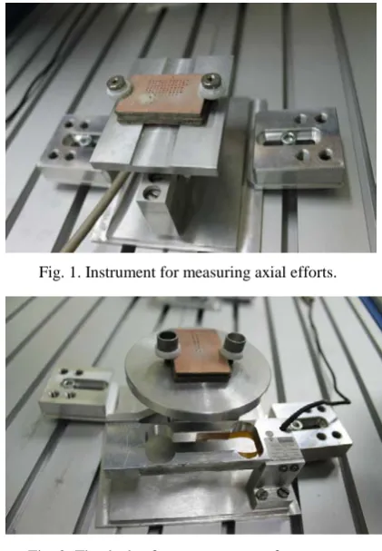
To measure the axial effort was the appliance is made on the basis of known methods and existing analogs, measuring element, which is the system of strain gauges mounted on the elastic casing (see fig. 1).
As for measurement of a torque, in our case the existing indirect method at which measurement is carried out by means of measurement of power of process of cutting is unsuitable as we deal with very low indicators. That is why it is necessary to use this method, which will make it possible to measure directly the torque with high precision. To this end, we have designed and manufactured a special device (see fig. 2), in which table for drilling is equipped with rotating lever mechanism. As the measuring element, elastic element applies here too with the system of load cells, only the higher strain measure (0.2 g).
Experiments were conducted with drills from solid alloy VK60M diameter φ 0,9mm long spiral groove l=10mm. Rake angle and spiral angle grooves respectively ω=300, rear angle was
180.
Drilling was carried out a package of printed circuit boards of fiberglass thickness 1.6mm composed of 5 plates with a total thickness of 8mm (see fig. 3).
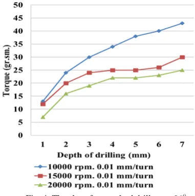
Drilling of blanks is carried out on different modes of cutting depth up to 7 mm and 1 mm the depth of the recorded testimony
every depth controlled readings. Experimental results are shown in fig. 4 and 5.
From this results, clearly shows that the load power with increasing depth progressively increasing. If the axial thrust is growing, approximately 1.5 times the amount of torque is increased 3-4 times.
Question, what caused this increase in power? Cutting conditions at the cutting edge of drills with increasing depth does not change. The only reason for this could be the increased contact area abrasive chips with the surface of the hole and emerged from it frictional forces.
You need to note that the sharp fall in axial efforts on areas of depth 2-3 and 5-6 (see fig. 5.) on these sites due to the lack of the work piece (fig. 3.) the copper layer.
The main factor increase the likelihood of brittle fracture of the cutting tool of these two power indicators may not increase the axial effort and more progressive increase in torque because the strength properties of carbide materials on the compression significantly exceed indicators of torsion.
Accelerating the process of chips from the cutting zone would contribute to the reduction of the force of friction and, consequently, improve the reliability of the drilling process. The problem of removal of chips when drilling deep hole in different cases decide in different ways. For example, when drilling drills dimensions solid this exercise method of leaching using a coolant, which is supplied, into the hole through, done in the body of the drill. In other cases, when the drill bit sizes do not give possibility of coolant above method to remove shavings used drilling method intermittent, where after a certain depth drilling is carried out periodically by the disqualification of drills from holes fast running.
The application of these techniques in our case nepriemlim. In the first case we have with micro drills. The use of coolant in the manufacture of printed circuit boards is not allowed. Design and method of intermittent drilling, because it led to the strong performance. When processing deep eyelet micro drills accelerating factor could be an increase in chip removal step spiral grooves, i.e. reducing the angle, but it would have led to a deterioration of the cutting conditions, so-as will decrease the cutting angle drills.
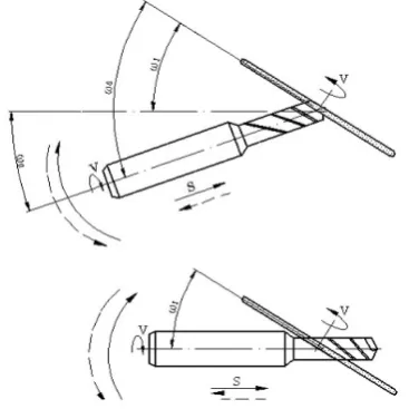
In the design of the drills carried out in a way that at the top of the save the desired cutting angle, and toward the end of the spiral grooves reduce its angle, IE a spiral groove cut into a vary-angle [1, 3, 4, 5, 6] and gradually increase its step, it would accelerate the process of chip and facilitate conditions for drilling. Fig. 6 shows the scheme of drills with vary-angle spiral grooves where the angle of the grooves at the top of the drill ω0,
and at the end of the working part of ω1. The width of the grooves
in the normal section Bn on all length does not change, but the
change in the front section and at the top is , cosω0
n To
B
B = and at
the end of the working parts
1 1
cosω
n T
B
B = .
Changing and useful mechanical drill section. Useful section
at the top: ,
cos 2
4 0
2
ω
π
no
S d
S = − and at the end of the working
Fig. 3. Package diagram printed circuit boards of 5 plates. 1-copper foil, 2-fiber, 3-double layer of copper foil.
1 2
3
8 1
3
4 5
6 0
7 2
Fig. 4.The chart for standard drills
parts: ,
cos 2
4 1
2
1 ω
πd Sn
S = − where Sn- square grooves in the normal
section, d - is the diameter of the drill.
If you take into account that ω0 > ω1, it turns out that toward
the end of the working part of the useful cross-section drills intensifies. Then there are drills compared to standard must withstand stress.
Production of such drills associated with certain difficulties. At production of standard drills with a constant tilt angle of a spiral flute the special adaptation carries out the mutually agreement two movement – rotations of preparation of a drill and its movement in the axial direction at a size of a step of a spiral flute. Thus, this interrelation is defined by linear function. In case of a variable step, this interrelation is defined by difficult tangential function. Because of it was necessary to modernize the equipment and its mechanism of axial giving of an element with the Archimedean spiral to replace elements with a tangential spiral, made by our special calculations [2, 3, 4, 5].
Besides, because of a variable tilt angle of a spiral flute, at you - polishing of these flutes should change orientation of a grinding wheel relatively to an axis of preparation of a drill respectively to change of a tilt angle of a flute. It can be carried out in two ways: at a motionless axis of a grinding spindle to turn a preparation spindle axis round a point of intersection of these axes at a corner size
ω
=
ω
0−
ω
1 (see figs. 7), or motionless toleave an axis of a spindle of preparation and to turn an axis of a grinding spindle (see figs. 8) [7].
Proceeding from constructive reasons the preference was given by us to the first option (figs. 7) and in the course of modernization of the equipment it was equipped with the additional mechanism of turn providing when cutting spiral flutes, turn of an axis of preparation of a drill relatively to an axis of a grinding spindle at a corner size
1
0
ω
ω
ω
=
−
thus depending on are long the cutting part of a drill turn is carried out by the linearlaw:
ω
х=
х⋅
К
ω,
whereω
х- the current size of an angle ofrotation of an axis of preparation,
х- the current coordinate oflength of the cutting part of a drill, Кω- the size of change of a tilt angle of a spiral flute per unit length the cutting part of a drill.
We have designed constructed prototypes of drills with vary-angle
ω
=
30
−
17
0,
, 20 35− 0
=
ω
ω
=40−220andω
=43−230.All of these included circuit boards same experiments as the standard. Experimental results for drills
ω
=
30
−
17
0 and0
20 35−
=
ω
are shown on fig. 9 – 12.Analysis of these graphs shows the following: for drills
0
17 30− =
ω performance of axial efforts almost indistinguishable from a standard drill bit ω=300,so, it was expected, because these same drill front angle and cutting conditions respectively at the cutting edge. With regard to indicators of torque, they drill
0 17 30− =
ω depending on the cutting was understated by 12-16%. Fig. 9.The chart of change of a torque for drills
Fig. 7. Schemes of change of orientation of axes of a spindle of preparation of a drill and grinding spindle. Method of turn of an axis of a spindle of preparation.
Fig. 8. Schemes of change of orientation of axes of a spindle of preparation of a drill and grinding spindle. Method of turn of a grinding spindle.
For drills 0
20
35
−
=
ω
performance of axial efforts relatively understated, as rake angle increased by 5% and this facilitated the process of cutting, but indicators of torque with increasing depth drilling grows more intensively and exceed indicators of both previous designs. It is clear that the understatement of torque to drillsω
=
30
−
17
0 compared with standard drills 030 =
ω , due to
the gradual increase in step spiral grooves and accordingly reduced contact area formed by chips with processed apertures. Increasing the angle of inclination and therefore a decrease in pitch of spiral drills
ω
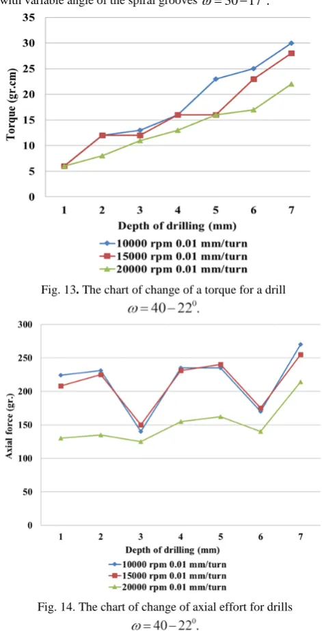
=35−200 again causes the reverse-torque figures intensively promoted.When drilling by drills of
ω
=40−220 and 023
43
−
=
ω
these power indicators are rather underestimated (see figs. 13-16) that is explained by improvement of conditions of cutting because of considerable (5-80) increases in a forward corner at the cutting edge. However, reduction of a corner of a point at further operation causes increase in intensity of wear, and they without repoint reach only 600-800 openings.
Obviously, to get a clearer picture further experiment need to
keep standard drills
ω
=
30
0 and drills with vari-angle spiralgrooves
ω
=
30
−
17
0.
Experiments were continued until the breakdown drills. Through each hole 200 checked power indicators, with increasing cutting edge wear gradually increases. After 1000 holes check carried out through every 100 holes, as increasing the likelihood of breakage of drill. Throughout a seriesof experiments for both types of drills,
ω
=
30
0 nearly identical indicators remain innovative wear and axial efforts. As for torque,its value on the standard drills always exceed the value of drills with variable angle of the spiral grooves
ω
=
30
−
17
0.
Statistics showed that the breakage of the standard drills
0
30
=
ω
going from 1200 to 1300 holes and drill with vari-Fig. 12.The chart of changes of axial efforts for drillsFig. 11.The chart of torque for drills
Fig. 14. The chart of change of axial effort for drills Fig. 13. The chart of change of a torque for a drill
angle
ω
=
30
−
17
0 from – 1400 to – 1500. Performance torque values before breakdown indicating the number of drilled holes N traversed the path L and size of wear on back surface drills f shown in Fig. 17 and 18.3.
Conclusions
Solid Carbide micro drills with vary-angle spiral grooves in deep drilling package provides improved chip control process intensity of hole, promoting this underestimates the force of friction and consequently the torque on the axis of the drill.
Implementation of the spiral grooves with a gradual lowering of the ω-angle from the top of the drill toward the end of the working part provides useful cross-section reinforcement drills, increasing the reliability of the brittle.
On the basis of the foregoing, it becomes possible to manufacture drills with elongated working part at 2-2, 5mm and in the package circuit boards add another plate, which will make it possible to improve the performance of drilling process on 20%.
4. Literature
1. B.Karpushewski, R.Turmanidze, L.Dübner,
O.Kushnarenko. Erhohung der standzeit und prozesssicherheit von mikrobohrern durch die entwicklung neuer werkzeuggeometrien. Collection of scientific works “Modern technologies in mechanical engineering”, publishing house of the Kharkov national technical university "KPI". Release 2. Kharkov, 2008 year. Pages 27-32.
2. D.Adamia, Z.Gviniashvili, V.Bachanadze. Peculiarities of formation of shavings grooves of spiral drill of hard alloy with variable inclination. Scientific technical journal “Transport and Machinebuilding” 2009 year. Edition No. 3(15). Publishing house “Transport and Machinebuilding”. Pages 133-140.
3. R.Turmanidze, O.Kushnarenko, D.Adamia,
Z.Gviniashvili. Small-sized hard metal spiral drills with variable angle of inclination chip grooves. Collection of scientific works “Modern technologies in mechanical engineering”, publishing house of the Kharkov national technical university "KPI". Kharkov, Release 5, 2010 year, Pages 318-327.
4. R.Turmanidze, D.Adamia, Z.Gviniashvili. Peculiarities of Manufacture and Tests of Fine-Sized hard-metal Spiral Drills with Variable Setting Angle of Chip Grooves. Proceedings of the 17th international scientific and technical conference “Mechanical Engineering and Technical Sphere of the XXI century”, 13-18 September 2010 year, in Sevastopol. Donetsk National Technical University. Volume 3. Pages 181-184.
5. R.Turmanidze, O. Kushnarenko, D. Adamia, Z.
Gviniashvili. Fine-sized hardmetal spiral drills with variable setting angle of chip grooves. 10th International scientific conference “New Ways in Manufacturing Technologies – NWMT 2010. 17-19 June 2010year. Prešov, Technical University of Košice, Faculty of Manufacturing Technologies, Košice, Slovak Republic. Pages 217-226.
6. R. Turmanidze, Z. Gviniashvili. Fine-sized hard metal spiral drills with variable setting angle of chip grooves. Selected, peer reviewed papers from the 6th International Congress of Precision Machining ICPM 2011. 13th–15th September 2011year. Liverpool John Moores University, Day 1. Liverpool. Pages 253-258.
7. D. Adamia, Z. Gviniashvili, L. Tediashvili, V. Bachanadze. Destination of swing-out mechanism on special device for chip groove fluting with variable angle of spiral. Scientific technical journal “Transport and Machinebuilding” #1(23), 2012 year. Publishing house “Transport and Machinebuilding”. Pages 196-205.
Fig. 16. The chart of change of axial effort for drills
Fig. 17. The chart of torque graph for drills and
before the breakdown drills .