ISSN: 2231-5381
http://www.ijettjournal.org
Page 133
FE Analysis of RC Circular Silo with
Variation in Height and Hopper Angle with
Constant Diameter
Arun L1, Mamatha K.K2
1
Assistant Professor, Department of Civil Engineering, Vidya Vikas Institute of Engineering & Technology, Mysuru, Karnataka, India.
2
P.G Student, Department of Civil Engineering, BGS Institute of Technology, B G Nagar, Karnataka, India.
Abstract
In this topical sprouting and industrializing
era. India is methodically growing up in Steel industry. Meanwhile, India is moving astoundingly towards economic growth in steel. The competitions in India are growing up day by day, in rising industries like Ceramics , Cement , Textiles industry etc., for the storage of solid raw materials. After so many research work carried out, it is still necessary to modify and alter the requirement of storing raw materials in a modified way. "Silos" is a special Shallow or Deep Structure, usually it has no distinctive or proper definition and can be defined usually by saying that it is used for storing "Solid bulks" materials. Furthermore, in other simple way it may be termed as Bins, Bunkers, Silos, or Tanks. "Silos" may be constructed of Steel or RCC (Reinforced cement concrete).These structures becomes important as it requires throughout the year in "Material handling" and "Food processing" plants for storing granular or fine materials i.e., {grains (in use for agriculture purpose),or fermented feed known as "Silage"}.
Keywords - FEM, Silo, SAP2000.
I. INTRODUCTION
Finite element analysis is traditionally a numerical method, basically from branch of mechanics of solids. A numerical Finite element analysis method can be simplified by saying " A solution that "Approximate" the exact solution " and hence in simple words Finite element analysis gives approximation to exact solution.
To solve any Differential or Integral equation a numerical method finite element is assumed to be discretizing a element into piecewise approximation called "Finite elements" and obtaining the functions of parameters by reducing the errors.
In wide range of engineering problems, the finite element method is a influential tool in solving numerical solutions. Finite element method can be applied in many fields like Dynamics, Solid mechanics, Structure analysis, Electrical analysis, Aerospace, Acoustics.
Steps of formulation in Finite element by plane stress and plane strain involves "Discretization " or "Mesh" generation involved during the pre-processing. Irregular, un deformed, geometric domain and its properties, connectives, physical constraints and their loadings are to be defined. Linear system of equations are solved by applying boundary conditions.
Development of Finite element analysis in new era
involving, Finite element analysis of integration converted into CAD design software. During analysis the self adaptive of mesh take place. Parallel computing of nodes take place in huge size during analysis of a problem model. Physical problem is analysed from the range of microscopic to macroscopic level in a multi-scale dynamic simulation analysis.
II. LITERATUREREVIEW
Suvarna Dilip Deshmukh and Rathod S.T [1]
:
Investigation was carried out on a industrial circular silo in Bhopal with concrete flat bottom is analysed and designed as per Indian Code provisions IS 4995 (Part 1)-1974 and also referring other Standard Codes like Euro code and ACI code. Cement is usually stored in Indian industries abundantly, thus the stored material inside the silo exerts traction force, frictional shear as well as normal pressure these parameters should be considered in design and also in consideration during seismic action. Strength design method is more speculative one. In calculating pressures, ACI codes is more speculative with other code provisions.
Dhanya Rajendran and Unni Kartha G [2] :
Discussed about a comparative study on RCC and
Steel silo of lateral analysis. Critical deformation are found at middle portion both in RCC and Steel silo. Steel silo shows more deformation. RCC silo shows less stress and displacement in wind load cases. Displacement decreases as the plate thickness increases meanwhile, the stress increases in Steel silo. Deformation and stresses will be more during empty condition than that of fully loading condition.
Krishna T Kharjule and Minakshi B Jagtap
[3] :ISSN: 2231-5381
http://www.ijettjournal.org
Page 134
for RCC silo without shear wall and displacement decreases for Steel silo with shear wall by using steel plate and thus increases the rigidity of the overall structures. RCC and Steel silo with shear wall experiences less time period of structures. In Time history analysis for both RCC and Steel silo base shear increases and acceleration of silo decreases.
Hamdy H.A. Abdel-Rahim [4] : Investigation
was carried out for wheat silos and its behaviour under seismic load. In earthquake areas, the ground motion effects and maximum pressure is significantly occurs at the base of silo. Slight fluctuations are obtained at tall silos. In large diameter silos, shear force and bending moment actions provoked by the earthquake ground motion. Silos are adversely affected by behaviour of earthquake by seismic response through dynamic analysis. Vibration of material increases in squat silo of larger diameter.
Riya Dey and Abhirup Bhattacharjee [5] :
Discussed about the comparison of RCC and Steel hopper designs. Dead weight is more in RCC hopper, whereas steel hopper are much less in dead weights. RCC hopper is cheaper compare to steel hopper and are more durable and stable. RCC hopper gives optimal result with a thickness having 250mm when compared with steel hopper having thickness of 10mm. Steel hopper are basically long usage, cost effective and very suitable in the areas of mining.RCC is more durable and suitable for storing granular materials.
III.SCOPE,OBJECTIVE,METHODOLOGY
This paper represents the geometric parameters
or overall geometry like * Hopper angles
* Varying heights
* State of stress in cylindrical wall
* Effects undergone by silos with different types of materials and its varying unique characteristic behaviour in silos.
The object and an attempt of this work is to carry
out an analysis, outlined the results obtained from analysis and studying various parameters like,
* The effects and influences of wall pressure and stress factors undergone by different materials by keeping the wall as rigid.
* Stress resultant, Forces, Displacement, Base shear, are investigated and computed in graphical form.
Two different materials with varying density
along with different filling conditions i.e., fully filled, partially filled (1/4,1/2) are chosen by keeping diameter constant with varying heights of cylindrical and hopper portion.
Analysis are done for different loads i.e., gravity
and lateral loads (Static analysis) and load combinations are incorporated.
GEOMETRIC PARAMETERS OF SILO
Table 1: Material properties
Table 2 : Load Combination
DL+LL+MAT1
DL+LL+MAT2
1.5(DL+LL+MAT1)
1.5(DL+LL+MAT2)
1.2(1DL+EQ)
1.2(2DL+EQ)
1.2(1DL+WL)
1.2(2DL+WL)
0.9(1DL)+1.5EQ
0.9(2DL)+1.5EQ
Description Model 1 Model 2 Model 3
Material 1 Wheat Wheat Wheat
Material 2 Cement Cement Cement
Volume 600 m3 600 m3 600 m3
Density of
material 1 (ρ) 8 KN/m
3
8 KN/m3 8 KN/m3
Density of material 2 (ρ)
15.5
KN/m3
15.5
KN/m3
15.5
KN/m3
Angle of
repose (ɸ) 30
°
45° 60°
Diameter of
silo (d) 6 m 6 m 6 m
Hopper
bottom
opening
1 m 1 m 1 m
Height of
cylindrical
portion
20.65 m 20.23 m 19.50 m
Height of
hopper
portion
1.44 m 2.5 m 4.33 m
f ck 30 N/mm2
f y 415 N/mm2
Density of concrete (ρ) 25 KN/m3
Cylindrical Beam (Top & Bottom ) 300x300 mm
Conical hopper Beam 200x200 mm
Column 500x500 mm
Bin 200 mm
Column height 8 m
ISSN: 2231-5381
http://www.ijettjournal.org
Page 135
Table 3 : Hand Calculation of Seismic base shear
(V b)
Fig 1: Combination of three cases of Seismic base shear (KN)
GENERATED SAP2000 MODEL
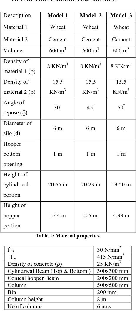
Fig 2: Generated SAP2000 model having load intensity with variation in hopper angle(30°, 45° & 60°) with
constant diameter
IV.RESULTS
1.DISPLACEMENTGRAPH FOR FULL,HALF AND
QUARTER LOAD CONDITIONS
Displacement along 'Z' direction (mm)
Hei
ght of
Silo (m
)
-2.75 -2.5 -2.25 -2 -1.75 -1.5 -1.25 -1 -0.75 -0.5 2
4 6 8 10 12 14 16 18 20 22 24 26 28
-2.75 -2.5 -2.25 -2 -1.75 -1.5 -1.25 -1 -0.75 -0.5 2
4 6 8 10 12 14 16 18 20 22 24 26 28
M2-D1-FL M2-D1-HL M2-D1-QL M2-D2-FL M2-D2-HL M2-D2-QL
Displacement along 'Z' direction (mm)
Hei
ght of
Silo (m
)
-2.75 -2.5 -2.25 -2 -1.75 -1.5 -1.25 -1 -0.75 -0.5 2
4 6 8 10 12 14 16 18 20 22 24 26 28
-2.75 -2.5 -2.25 -2 -1.75 -1.5 -1.25 -1 -0.75 -0.5 2
4 6 8 10 12 14 16 18 20 22 24 26 28
M3-D1-FL M3-D1-HL M3-D1-QL M3-D2-FL M3-D2-HL M3-D2-QL
Zone V
Zone factor (Z) 0.36
Importance factor (I) 1
Response reduction factor (R) 5
Damping ratio 5%
Soil type II
Sa/g 2.5
Column (0.50 x 0.50) m
Conical Hopper Beam (0.20 x 0.20) m
Cylindrical Beam (Top &
Bottom) (0.30 x 0.30) m
Thickness of Shell and Hopper 0.2 m
Column Length 8 m
Design horizontal seismic coefficient
(Ah) =
g Sa
R I Z
2
0.09 0.09 0.09
Design seismic
base shear (Vb)
V b=Ah*W1
666.51 KN
703.32 KN
746.44 KN
Design seismic
base shear (Vb)
V b=Ah*W2
1071.51 KN
1108.32 KN
ISSN: 2231-5381
http://www.ijettjournal.org
Page 136
Fig 3 : Combination of Displacement graph for hopper angle 30°, 45° & 60° for full, half, quarter condition with material having different densities
2. FORCE RESULTANT for full load conditions for hopper angle 30°, 45° & 60° in fxx direction
Height of Silo (m)
Res ulta nt for ces along F xx dir ec tion (Kn/ m)
0 2.5 5 7.5 10 12.5 15 17.5 20 22.5 25 -200 -150 -100 -50 0 50 100 150 200 250 300 350
0 2.5 5 7.5 10 12.5 15 17.5 20 22.5 25 -200 -150 -100 -50 0 50 100 150 200 250 300 350
0 2.5 5 7.5 10 12.5 15 17.5 20 22.5 25 -200 -150 -100 -50 0 50 100 150 200 250 300 350 M1-D1-Fxx M1-D2-Fxx
Height of Silo (m)
Res
ulta
nt for
ce al
ong Fxx di
rec
tion (Kn/m
)
0 2.5 5 7.5 10 12.5 15 17.5 20 22.5 25 -200 -150 -100 -50 0 50 100 150 200 250 300
0 2.5 5 7.5 10 12.5 15 17.5 20 22.5 25 -200 -150 -100 -50 0 50 100 150 200 250 300
0 2.5 5 7.5 10 12.5 15 17.5 20 22.5 25 -200 -150 -100 -50 0 50 100 150 200 250 300 M2-D1-Fxx M2-D2-Fxx
Height of Silo (m)
Res ulta nt for ces along F xx dir ec tion (Kn/ m)
0 2.5 5 7.5 10 12.5 15 17.5 20 22.5 25 -150 -100 -50 0 50 100 150 200 250 300
0 2.5 5 7.5 10 12.5 15 17.5 20 22.5 25 -150 -100 -50 0 50 100 150 200 250 300
0 2.5 5 7.5 10 12.5 15 17.5 20 22.5 25 -150 -100 -50 0 50 100 150 200 250 300 M3-D1-Fxx M3-D2-Fxx
Fig 4 : Height v/s Resultant Force for hopper angle 30°, 45° & 60° for full load condition with material
having different densities
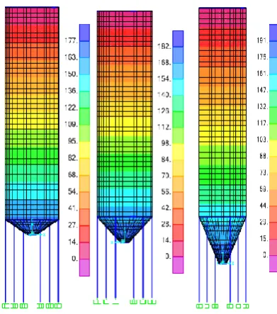
3.Shear Resultant for full load conditions for hopper angle 30°, 45° & 60° in Sxx (Top & Bottom) direction
Height of Silo (m)
Stress resultant a
long
Sxx at top
(mm)
0 2.5 5 7.5 10 12.5 15 17.5 20 22.5 25 -1.25 -1 -0.75 -0.5 -0.25 0 0.25 0.5 0.75 1 1.25 1.5 1.75
0 2.5 5 7.5 10 12.5 15 17.5 20 22.5 25 -1.25 -1 -0.75 -0.5 -0.25 0 0.25 0.5 0.75 1 1.25 1.5 1.75
0 2.5 5 7.5 10 12.5 15 17.5 20 22.5 25 -1.25 -1 -0.75 -0.5 -0.25 0 0.25 0.5 0.75 1 1.25 1.5 1.75 M1-D1- TOP-Sxx M1-D2- TOP-Sxx
Height of Silo (m)
Stre
ss re
sultant alo
ng Sxx at
bottom
(mm
)
0 2.5 5 7.5 10 12.5 15 17.5 20 22.5 25 -0.6 -0.4 -0.2 0 0.2 0.4 0.6 0.8 1 1.2
0 2.5 5 7.5 10 12.5 15 17.5 20 22.5 25 -0.6 -0.4 -0.2 0 0.2 0.4 0.6 0.8 1 1.2
0 2.5 5 7.5 10 12.5 15 17.5 20 22.5 25 -0.6 -0.4 -0.2 0 0.2 0.4 0.6 0.8 1 1.2 M 2-D1-Bottom-Sxx M 2-D2-Bottom-Sxx
Height of Silo (m)
Stress resultant a
long
Sxx at top
(mm)
0 2.5 5 7.5 10 12.5 15 17.5 20 22.5 25 -0.6 -0.5 -0.4 -0.3 -0.2 -0.1 0 0.1 0.2 0.3 0.4 0.5 0.6
0 2.5 5 7.5 10 12.5 15 17.5 20 22.5 25 -0.6 -0.5 -0.4 -0.3 -0.2 -0.1 0 0.1 0.2 0.3 0.4 0.5 0.6
0 2.5 5 7.5 10 12.5 15 17.5 20 22.5 25 -0.6 -0.5 -0.4 -0.3 -0.2 -0.1 0 0.1 0.2 0.3 0.4 0.5 0.6 M3-D1-Top-Sxx M3-D2-Top-Sxx
Fig 5 : Height v/s Shear Resultant for hopper angle 30°, 45° & 60° for full load condition with material having
different densities
V. CONCLUSION
1. 'Higher lateral displacement' are seen in silos
having fully filled condition other than half and
quarterly filled condition
.
2. The variations is observed only in hopper portion
whereas the cylindrical portion is linear, it is
clearly seen that displacement following linear variations can be used for safety purpose for fully filled condition.
3. Seismic weights of the material increases due to
its varying densities and has a affect on stress at junction of wall and hopper section.
4. Base shear increases up to 30 to 40 % due to the
material densities.
5. Stored materials and its varying densities is
directly proportional to the state of stress in cylindrical portions
REFERENCES
[1] Suvarna Dilip Deshmukh, Rathod S.K (2015) "Comparison of design and seismic behaviour of RCC silo'' International journal of science and research, volume 4, Issue 5.
[2] Dhanya Rajendran, unni kartha G "Comparison of Lateral analysis of reinforced concrete and steel silo" International journal of civil engineering and technology, volume 5, Issue 12, December (2014) pp 16-24.
[3] Krishna T Kharjule, Minakshi B Jagtap "Seismic analysis of RCC and steel silos" International journal of computational engineering research, volume 5, Issue 7, July 2015. [4] Hamdy H.A. Abdel-Rahim "Response the cylindrical elevated
wheat storage silos to seismic loading" IOSR journal of engineering, volume 4, Issue 1, pp 42-55.
ISSN: 2231-5381
http://www.ijettjournal.org
Page 137
engineering and technology , volume 6, Issue 6, June (2015), pp 114-123.
[6] K.Dharani and D. Jeyakumar (2016) "A brief review on bunkers and silos" International journal for research in applied science and engineering technology", volume 4,Issue X, ISSN: 2321-9653.
[7] Mohamed T. Abdel-Fattah, Ian D. Moore, and Tarek T. Abdel-Fattah, (2006) "Behaviour of elevated concrete Silos filled with saturated Solids", NRC Research Press Web, Vol. 227, pp (33-239).
[8] Nateghi F and Yakhchalian M (2012) "Seismic Behaviour of Silos with Different Height to Diameter Ratios Considering Granular Material-structure Interaction", Structural Engineering Research Centre, Iran, Vol. 25, No. 1, pp ( 26-37).
[9] ACI Committee 318, Building Code Requirements for Reinforced Concrete (ACI 318-83), American Concrete Institute, Detroit, 1983.