Design, Modeling and Failure Analysis of Car
Front Suspension Lower Arm
Mr.Sushilkumar P.Taksande Dr. A.V.Vanalkar
M.Tech Scholar Professor
Department of Mechanical Engineering Department of Mechanical Engineering
K.D.K.C.E. Nagpur, India K.D.K.C.E. Nagpur, India
Abstract
This paper presents design, modeling and analysis of car front suspension lower arm to study the stress condition and to select the suitable materials for the front suspension lower arm. The main objectives of this study to determine critical locations and strain distributions of the component. The paper aims to complete Finite Element Analysis of the front suspension lower arm which consist the stress optimization loadings and analysis for deformation.
Keywords: Lower Suspension Arm, Fatigue Failure, Vehicle, Modeling, Fea Analysis
________________________________________________________________________________________________________
I.
I
NTRODUCTIONThe vehicle suspension system is responsible for driving comfort and safety as the suspension carries the vehicle-body and transmits all forces between body and road. Positively, in order influence these properties, semi-active or active components are introduced, which enable the suspension system to adapt to various driving conditions. From a design point of view, there are two main categories of disturbances on a vehicle namely the road and load disturbances. Road disturbances have the characteristics of large magnitude in low frequency (such as hills) and small magnitude in high frequency (such as road roughness). Load disturbances include the variation of loads induced by accelerating, braking and cornering. Therefore, a good suspension design is concerned with disturbance rejection from these disturbances to the outputs. A conventional suspension needs to be “soft” to insulate against road disturbances and “hard” to insulate against load disturbances. Consequently, the suspension design is an art of compromise between these two goals. The Wishbone lower arm is a type of independent suspension used in motor vehicles. The general function of control arms is to keep the wheels of a motor vehicle from uncontrollably swerving when the road conditions are not smooth. The control arm suspension normally consists of upper and lower arms. The upper and lower control arms have different structures based on the model and purpose of the vehicle. By many accounts, the lower control arm is the better shock absorber than the upper arm because of its position and load bearing capacities In the automotive industry, the riding comfort and handling qualities of an automobile are greatly affected by the suspension system, in which the suspended portion of the vehicle is attached to the wheels by elastic members in order to cushion the impact of road irregularities.
The specific nature of attaching linkages and spring elements varies widely among automobile models. The best rides are made possibly by independent suspension systems, which permit the wheels to move independently of each other. In these systems the unsprung weight of the vehicle is decreased, softer springs are permissible, and front-wheel vibration problems are minimized. Spring elements are used for automobile suspension, increasing order of their ability to store elastic energy per unit of weight.
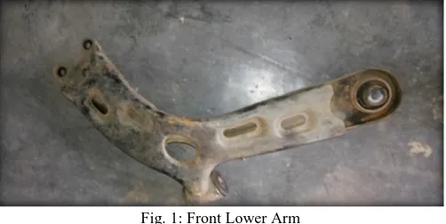
Fig. 1: Front Lower Arm
of the cases the failures are catastrophic in nature. So the structural integrity of the suspension arm is crucial from design point of view both in static and dynamic conditions. As the Finite Element Method (FEM) gives better visualization of this kind of the failures so FEM analysis of the stress distributions around typical failure initiations sites is essential. Therefore in this dissertation work it is proposed to carry out the structural analysis of lower suspension arm of light commercial vehicle using FEM.
The suspension arm gets more attention by many researches like study dynamic analyses of the motor vehicle suspension system using the point-joint coordinate’s formulation. The mechanical system is replaced by an equivalent constrained system of particles and then the laws of particle dynamics are used to derive the equations of motion. Modeling and simulation are indispensable when dealing with complex engineering systems. It makes it possible to do an essential assessment before systems are developed. It can alleviate the 9need for expensive experiments and provide support in all stages of a project from conceptual design, through commissioning and operation. The most effective way to improve product quality and reliability is to integrate them in the design and manufacturing process.
II.
L
ITERATURE REVIEW Hemin M. MohyaldeenA.
This papers describes the analysis of lower automobile suspension arm using stochastic design improvement technique. The suspension system is one of the most important components of vehicle, which directly affects the safety, performance, noise level and style of it. The objectives of this study are to characterise the dynamic behavior, to investigate the influencing factors of lower suspension arm using FEM incorporating design of experiment (DOE) and artificial neural network (ANN) approach and to analysis the lower suspension arm using robust design method. The structural three-dimensional solid modeling of lower arm was developed using the Solid works computer-aided drawing software. The three dimensional solid model then imported to the MSC.PATRAN software and employed to generate meshes and defined material properties for the finite element modeling. The linear elastic analysis was performed using NASTRAN codes. The optimization of lower suspension arm were carried out using stochastic design improvement based on Monte Carlo approach, Response surface methodology(RSM) based on central composite design (CCD) and artificial intelligent technique based on radial basis function neural network (RBFNN). Tetrahedral element with 10nodes (TET10) and tetrahedral element with 4 nodes (TET4) mesh were used in the stress analysis. The modal analysis was performed with using Lanczos method to investigate the deigen value and mode shape. The highest von Mises stresses of TET10were selected for the robust design parameter. The development from the Stochastic
Design Improvement (SDI), RSM and ANN are obtained. The design capability to highest load with lower predicted stress is identified through the SDI process.CCD used to predict and assess linear response Von Mises and Displacement on Lower arm systems models. On the other hand, RBFNN used to investigate linear response of lower arm. It can be seen that the robust design was capable to optimize the lower vehicle arm by using stochastic optimization and artificial intelligent techniques. The developed linear model based on SDI and CCD is statistically adequate and can be used to navigate the design space. A new parameter of material can be reconsidered in order to optimize the design. The results can significantly reduce the cost and time to market, improve product reliability and custom confidence. These results can be use as guideline before developing the prototype.
Lihui Zhao B.
MohdKhairilAzirul Bin Khairolazar C.
This project presents the development of robust design of lower suspension arm using stochastic optimization. The strength of the design analyze by finite element software. The structural model of the lower suspension arm was mode by using the solid works. The finite element model and analysis were performed utilizing the finite element analysis code. The linear elastic analysis was performed using NASTRAN codes. TET10 and TET4 mesh has been used in the stress analysis and the highest Von Mises stress of TET10 has been selected for the robust design parameter. The development of Robust design was carried out using the Monte Carlo approach, which all the optimization parameter for the design has been optimized in Robust design software. The improvements from the Stochastic Design Improvement (SDI) are obtained. The design capability to endure more pressure with lower predicted stress is identified through the SDI process. A lower density and modulus of elasticity of material can be reconsidered in order to optimize the design.
The area of the design that can be altered for the optimization and modification is identified through the stress analysis result. As a conclusion, the robust design by using stochastic optimization was capable to optimize the lower arm suspension. Thus, all the result from this project can be use as guideline before developing the prototype.
III.
O
BJECTIVE 1) The main aim is to investigate the failure of the lower arm.2) To describe a computer-based approach to the car front suspension design problem.
3) Study the existing component design and its function for identifying potential areas for modification 4) Evolve a Test plan for validating the F.E.A Methodology
5) Recommend the new design for implementation
6) To analysis of the suspension arm using ANSYS Software.
IV.
R
ESEARCH METHODOLOGYIn this project, we are using CAD and Analysis softwares like Creo-Parametric 2.0 and ANSYS Version 13.0. Here we can prepare a CAD model of lower arm in Creo-Parametric 2.0 and determine the stress value and deform value in ANSYS 13.0. To study various stresses and deform values is acting on lower arm. CAD model of lower arm is designed in Creo-Parametric 2.0 was imported in ANSYS software for meshing and different results. Meshed model of the lower arm essentially consist of nodes and elements. Tetra elements give enhanced result as compared to other types of elements, therefore the elements used in this analysis is tetra elements. The material Fe410 and Fe510 was used for lower control arm. Calculated forces and boundary conditions were applied on meshed model in ANSYS 13.0. Static and modal analysis was performed by using ANSYS 13.0. Design parameters obtained from above Finite Element Analysis were compared for above stated materials and best one was selected
V.
A
NALYTICAL CALCULATIONFig. 2: The geometric parameter of wheel axle and arms
By the wheel of the car (if driving) torque applied Ткand it rotates with angular velocity ωк . Wheel of the car with the help of independent suspension is related to the car body and has an angular stiffness Сβр, and stiffness Ср compression springs.Some numerical results are by definition a number of parameters that characterize the work areas 1 and 2 rod stabilizer which has the following kinematic and geometric source parameters.
Calculate: A.
The angular stiffness front suspensions (Сβр1) : Сβp1 = 2Cp1 * L2
=26 * 68.252 Сβp1 =121109.62 kgs∙cm
The angular stiffness rear suspensions (Сβр2) : Сβp2 = 2Cp2 * L2
= 30 * 68.252 Сβp2 =139741.87 kgs∙cm
We also calculate the angular stiffness of the tire: Сβш1 = Сβш2 = 2Сш * L2
= 204 * 68.252 Сβш1= Сβш2 = 950244.75 kgs∙cm
Find given angular rigidity front suspensions (Сβ1) : Сβ1 =
=
Сβ1=107418.96kgs∙cm
Find given angular rigidity rear suspensions (Сβ2): Сβ2 =
= Сβ2=121826.24kgs∙cm Effective roll arm (h3) : h3 = hg – h2 *
h3 = 580 – 320 * h3 = 420 mm h3 = 42 cm
Fig. 3: Centre of gravity and parameters of car base
We define the angle of heel corresponding parameters calculated from the dependence :
β =
when, μ -Specific lateral force applied at the center of gravity of the body and can be taken as 0.4, Ws -Weight acting on one side of suspension = 1200 kg
β = = = β = 0.112rad β = 6°41´
With the effective rolling arm h3 defined, it is possible to calculate the roll moment (Troll) applied to the vehicle due to the lateral acceleration imposed:
Troll = M * aL * h3
M = Vehical mass, kg ; assume M = 1600 kg aL = lateral acceleration, m/s
h3 = effective roll arm, m Troll = M * aL * h3
Troll = 1600 * 22.22 * 0.42 Troll = 14931.84 Nm
Then calculate the roll gradient (Kroll) :
Kroll =
where, Kroll = Roll gradient
Kt = Сβp1 = Vehicle’s total roll stiffness
Kroll = Kroll =
Kroll = 0.12
Fig. 4: represents the turning of vehicle and its parameters
The forces per axle can be calculated as follows: Front axle force (Ffront) :
Ffront = * M * aL
Ffront =
* 1600 * 22.22
Ffront = 17776 N
Finite Element Analysis: B.
Finite Element Analysis (F.E.A) is a powerful technique used for solving complicated mathematical problem of engineering and physics such as structural analysis, heat transfer, fluid flow, mass transport and electromagnetic potential. Modem F.E.A. generated by computer software allows engineer to subject a computer model of structure to various loads to determine how it will react. The environment is defined through a combination of loads and constraints and the decisions or assumptions that about those loads and constraints are very important to the overall accuracy of the simulation. It also enables designs to be quickly modeled, analyzed, changed, checked for feasibility and structural integrity, redesigned or discarded if they do not work.
FEA is used in problems where analytical solution not easily obtained Mathematical expressions required for solution not simple because of complex geometries loadings material properties.
Basic FEA Equation: C.
The fundamental FEA equation is this assumption greatly simplifies problem formulation and solution. [F] = [K] * [d]
where:
[F] is the known vector of nodal loads [K] is the known stiffness matrix
[d] is the unknown vector of nodal displacements
Principal Steps Of Finite Element Analysis : D.
There are three steps of finite element analysis are
Pre-Processing 1) Solver 2) Post-Processing 3)
a)Pre-Processing :
The user constructs a model of the part to be analyzed in which the geometry is divided into a number of discrete sub regions, or elements," connected at discrete points called \nodes." Certain of these nodes will have fixed displacements, and others will have prescribed loads. These models can be extremely time consuming to prepare, and commercial codes vie with one another to have the most user-friendly graphical pre-processor" to assist in this rather tedious chore. Some of these pre-processors can overlay a mesh on a pre existing CAD, so that finite element analysis can be done conveniently as part of the computerized drafting-and-design process.
b)Solver:
The dataset prepared by the pre processor is used as input to the finite element code itself, which constructs and solves a system of linear or nonlinear algebraic equations
Kijuj = fi
where u and f are the displacements and externally applied forces at the nodal points. The formation of the K matrix is dependent on the type of problem being attacked, and this module will outline the approach for truss and linear elastic stress analyses. Commercial codes may have very large element libraries, with elements appropriate to a wide range of problem types. One of FEA's principal advantages is that many problem types can be addressed with the same code, merely by specifying the appropriate element types from the library.
Fig. 5: FEA
c)Post Processing :
In the earlier days of finite element analysis, the user would pore through reams of numbers generated by the code, listing displacements and stresses at discrete positions within the model. It is easy to miss important trends and hot spots this way, and modern codes use graphical displays to assist in visualizing the results. A typical postprocessor display overlays colored contours representing stress levels on the model, showing a full field picture similar to that of photo elastic or moiré experimental results. The operation of a specific code is usually detailed in the documentation accompanying the software, and vendors of the more expensive codes will often over workshops or training sessions as well to help users learn the intricacies of code operation. One problem users may have even after this training is that the code tends to be a black box" whose inner workings are not understood. In this module we will outline the principles underlying most current Finite element stress analysis codes, limiting the discussion to linear elastic analysis for now. Understanding this theory helps dissipate the black-box syndrome, and also serves to summarize the analytical foundations of solid mechanics.
ANSYS Simulation: E.
When performing finite element analysis (FEA) a virtual model of a real world situation is set up to see how a product will react in its environment. The environment is defined through a combination of loads and constraints and the decisions or assumptions that about those loads and constraints are very important to the overall accuracy of the simulation. The complicating factors related to defining loads and constraints such as :
Difficult placing of loads and constraints particularly for situation involving motion, impact, time-dependent changes or multiphysics phenomena. Historically, engineering experience and judgment was relied upon to determine loads and constraints and how to best apply them. However, even experienced engineers can have difficulty determining accurate values for these critical inputs.
VI.
P
ART DESIGN&
DETAILING OF LOWER ARM(
CAD MODEL)
Part Design:
Existing Lower Arm:
Existing Lower Arm: A.
Fig. 6: CAD Model Of Existing Lower Arm
Modified Lower Arm: B.
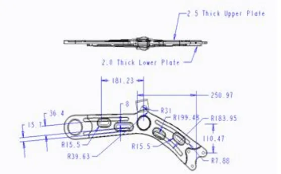
Drafting and Detailing Of Lower Arm: C.
Existing Lower Arm: 1)
Fig. 8: Drafting Of Existing Lower Arm
Modified Lower Arm : 2)
Fig. 9: Drafting of Modified Lower Arm
Material Properties: D.
We use three types of material are as :
EN 24
Fe 410
Fe 590
EN 24: 1)
Density = 7850 kg/mm3
Young's Modulus = 2.1 x 10⁵ Mpa Poisson's Ratio = 0.3
Yield Tensile Strength = 680 Mpa Yield Compressive Strength = 680 Mpa Ultimate Tensile Strength = 850 Mpa Ultimate Compressive Strength = 0 Mpa
Fe 410: 2)
Density = 7685 kg/mm3
Young's Modulus = 2.1 x 10⁵ Mpa Poisson's Ratio = 0.285
Ultimate Compressive Strength = 0 Mpa
Fe 590: 3)
Density = 7850 kg/mm3
Young's Modulus = 2 x 10⁵ Mpa Poisson's Ratio = 0.3
Yield Tensile Strength = 490 Mpa Yield Compressive Strength = 490 Mpa Ultimate Tensile Strength = 590 Mpa Ultimate Compressive Strength = 0 Mpa
ANSYS Simulation Analysis: E.
Static Structural Analysis: 1)
The ANSYS structural analysis software suite is trusted by organizations around the world to rapidly solve complex structural engineering problems with ease. In this project FEA analysis tools from ANSYS provide the ability to simulate every structural aspect of a product.
Linear static analysis that simply provides stresses or deformations. Modal analysis that determines vibration characteristics. Advanced transient nonlinear phenomena involving dynamic effects and complex behaviors.
Meshing: 2)
ANSYS meshing technologies provide physics preferences that help to automate the meshing process. For an initial design, a mesh can often be generated in batch with an initial solution run to locate regions of interest. Further refinement can then be made to the mesh to improve the accuracy of the solution. There are physics preferences for structural, fluid, explicit and electromagnetic simulations. By setting physics preferences, the software adapts to more logical defaults in the meshing process for better solution accuracy.
Other physics-based features that help with structural analysis include:
Automated beam and shell meshing
Editable contact definitions
CAD instance modeling/meshing
Rigid-body contact meshing
Solver-based refinement
Thin solid-shell meshing
After Meshing in ANSYS Software, find outs Nodes and Elements
Existing Lower Arm: F.
Nodes: 55735 Element: 28643
Fig. 10: Meshing of Existing Lower Arm
Modified Lower Arm: 1)
Fig. 11: Meshing of Modified Lower Arm
Boundary Condition : 2)
Fixed Support
Frictionless Support
Force a)Fixed Support:
Fig. 12: Fixed Support
b)Frictionless Support :
Fig. 13: Frictionless Support
c)Force:
VII.
R
ESULTS AND DISCUSSION Results of Lower Arm:A.
Existing Lower Arm: Material: EN 24 Modified Lower Arm Material: EN 24 Fe 410 Fe 590
Existing Lower Arm : B.
EN 24 1)
Total Deformation Max.= 67.779 mm
Fig. 15: Results of Total Deformation
von-Mises Stress Max. = 6068.2 MPa
Fig. 16: Results of von-Mises Stress
Fig. 17: Results of Max Shear Stress
Modified Lower Arm : 2)
a)EN 24
Total Deformation Max.= 47.907 mm
Fig. 18: Results of Total Deformation
von-Mises Stress Max. = 4494.4 MPa
Fig. 19: Results of von-Mises Stress
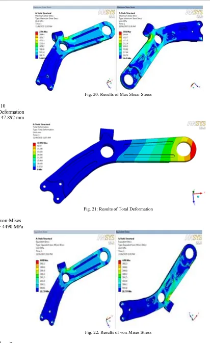
Fig. 20: Results of Max Shear Stress
b)Fe 410
Total Deformation Max.= 47.892 mm
Fig. 21: Results of Total Deformation
Stress von-Mises Max. = 4490 MPa
Fig. 22: Results of von-Mises Stress
Fig. 23: Results of Max Shear Stress
Fe 590 3)
Total Deformation Max.= 50.302 mm
Fig. 23: Results of Total Deformation
von-Mises Stress Max. = 4494.4 MPa
Fig. 24: Results of von-Mises Stress
Max. = 2356 MPa
Fig. 25: Results of Max Shear Stress
VIII.
R
ESULTS COMPARISONFig. 26: Results Comparison
IX.
C
ONCLUSIONIn this project it has been seen that the maximum value of force transmitted by tyre to the body of vehicle through lower suspension arm. During braking and cornering lower suspension arm is subjected to high stresses because of that Failure of lower suspension arm of vehicle was reported. Plastic deformation and cracks were observed frequently during on road running of vehicle. Stress analysis was performed using finite element method. Further corrective actions that are modifications in design will be carried on the basis of results analysis.First stage results show higher stress effects on the component. The existing part is concerned with material properties distribution in which optimization is performed on a model to create a new suspension lower arm for the structure, removing any unnecessary material in the arm. In this project, the stress analysis is done with the help of ANSYS 13.0 software.The stress and deformation effect on suspension lower arm was investigated under vehicle loading. The behavior of lower arm are very important parameters in stress distribution near loading and bush portion of the lower arm. This application are related experiments will be the subject of further modifications.
In this project, we conclude that the stress analysis for considering lower arm deformation, von-Misses Stress and Max shear stress and also using different lower arm materials were tested and it was observed that Fe410 material was much better than the EN 24 material.
R
EFERENCES [1] HeminM.Mohyaldeen University Malaysia Pahang[2] Lihui Zhao College Of Mechanical Engineering, University Of Shanghai For Science And Technology, Shanghai 200093, Pr China. [3] MohdKhairilAzirul Bin Khairolazar Faculty Of Mechanical Engineering University Malaysia Pahang
[4] Kyrre, S.A. 2006. Fatigue life prediction of an alluminium alloy automotive component using finite element analysis of surface topography. PhD Thesis Dissertation. Norwegian University of Science and Technology Department of Structural Engineering.
[5] Kyrre, S.A., Skallerud, B., Tveiten, W.T. and Holme, B. 2005. Fatigue life prediction of machined components using finite element analysis of surface topography, International Journal of Fatigue. 27: 1590- 1596.
[6] Nadot, Y. and Denier, V. 2003. Fatigue failure of suspension arm: experimental analysis and multiaxial criterion. International journal of Fatigue, 11 (4): 485 – 499.
[7] Smith, R. A., 1999, Fatigue in transport: Background, Solutions and Problems, Fatigue ’99, Proceedings of the Seventh International Fatigue Congress, edited by Wu, X. R., and Wang, Z. G., Beijing, P.R. China, pp 2583-2590.
[8] Rill, G., 2006, “Vehicle Modeling by Subsystems”, Journal of the Brazilian Society of Mechanical Sciences and Engineering, Vol. 28, No. 4.
[9] Shirahatt, A., Prasad, P.S.S., Panzade, P., Kulkarni, M.M., 2008, “Optimal Design of Passenger Car Suspension for Ride and Road Holding”. Journal of the Brazilian Society of Mechanical Sciences and Engineering, Vol. 30, No. 1.
[10] Wong, J.Y., 2001, “Theory of Ground Vehicles”, John Wiley & Sons Inc., New York, USA.
[11] Goldberg D.E., “Genetic Algorithms in Search, Optimization, and Mechanical Learning”, Addison Wesley, 1989