Development of a Virtual Reality Cycling Simulator
Filip Schramka
1, 2*, Stefan Arisona
1, 2, Michael Joos
1, Alexander Erath
11 ETH Zurich, Future Cities Laboratory, Singapore-ETH Centre, 1 CREATE Way, CREATE Tower, Singapore. 2 FHNW, Institute of 4D Technologies, Bahnhofstrasse 5, 5210 Windisch, Switzerland.
* Corresponding author. Tel.: +41 56 202 75 27; email: filip.schramka@fhnw.ch Manuscript submitted June 10, 2017; accepted August 13, 2017.
doi: 10.17706/jcp.13.6 603-615.
Abstract: This paper presents a cycling simulator implemented using consumer virtual reality hardware and additional off-the-shelf sensors. Challenges like real time motion tracking within the performance requirements of state of the art virtual reality are successfully mastered. Retrieved data from digital motion processors is sent over Bluetooth to a render machine running Unity3D. By processing this data, a bicycle is mapped into virtual space. Physically correct behaviour is simulated and high quality assets are added to create a full immersive virtual reality experience. Our whole source code is published under an open source licence on GitHub. Ultimately, the cycling simulator will be used for behavioural studies to measure how different street design configurations and traffic levels impact perceived cycling stress level, cognitive reactions and mobility behaviour.
Key words: Computer graphics, simulation, game engines, human mobility, virtual reality, movement tracking.
1.
Introduction
To achieve all this, a robust hard- and software framework is developed which is able to track all essential parts of the bike. Technologies like Bluetooth Low Energy, Gyroscopes and Accelerometers were combined into small tracking sensors. Furthermore, all components achieve the performance required by state of the art virtual reality applications. The results of our development brought us an appropriate tool for further research. In its current state, the cycling simulator is capable of supporting behavioural studies to measure how different street design configurations and traffic levels impact perceived cycling stress level, cognitive reactions and mobility behaviour. The source code is published on GitHub under MIT license (EngagingMobility, 2017).
2.
Related Work
In this section, we introduce existing work in the area of bicycle simulation, followed by problems of the latest generation of virtual reality technologies and how different approaches handle them. Furthermore, we introduce a theory that explains why motion sickness occurs during VR simulation.
2.1.
Existing Projects within the Area of
VR
Bicycle Simulation
The idea of a biking simulation within a virtual environment is not new. Multiple researchers have successfully implemented prototypes over the years. We will give an overview of those implementations.
Schulzyk et al. built a high-end bicycle simulator with a motion platform which simulates physical forces and the street. This allowed them to create a higher depth of immersion in combination with a three-walled cave (Schulzyk, Bongartz, Bildhauer, Hartmann, & Herpers, 2008). More similarities to our simulator has Mestre et al. with their research about the effect of virtual reality in sportive applications. They also used a stand and not a motion platform, but they have no further sensors to achieve more freedom in the virtual scene (Mestre, Dagonneau, & Mercier, 2011). Furthermore Ranky et al. developed a framework which allows to transform every bike into a cycling simulator by adding various sensors all over the bike. They used a monitor as output, which does not create a very immersive environment (Ranky, Sivak, Lewis, Gade, Deutsch, & Mavroidis, 2010). Another bicycling simulator was developed by Hurwitz et al. at the Oregon State University. The bike was mounted on a movable platform and a large projection screen was used for the virtual environment (Hurwitz, 2015). There are also projects which propose similar sensors for tracking as we do, but not in the cycling context. Kim et al. developed a data glove which was able to motion track the users hand. They also used accelerometers and Bluetooth to achieve the movement tracking (Kim, Thang, & Kim, 2009).
A great inspiration and knowledge source for this project was the cycling simulator CyclingSPACES (Breda, 2015) developed by Atlantis Games in collaboration with the Breda University of Applied Sciences - NHTV (insight, 2015).
2.2.
Technical Limitations with State of the Art Virtual Reality
After many years of development and an existence as niche product VR found its way into the consumer market. Small form factor displays with high pixel densities are widely available on the market and are used to build modern Head Mounted Displays (HMDs). Nevertheless, there are still technical issues like the lack of performance. The graphics hardware needs to render a resolution equivalent to 3024x1680 pixels for VR games and applications, and need to do so at a sustained 90FPS (NVIDIA, Virtual Reality Technology, 2016). The amount of pixels is therefore ~2.5 times higher than what is required by common display hardware with a resolution of 1920x1080. The 3D graphics acceleration manufacturer NVIDIA (NVIDIA, Pascal and VRWorks Infuse VR with New Level of Presence, 2016) proclaims that any performance dip, even the slightest stutter, could cause discomfort and ruin the VR experience. Technologies like Asynchronous
Level of Presence, 2016), Lens Matched Shading (NVIDIA, Lens Matched Shading and Unreal Engine 4 Integration Part 1, 2016) and many more try to improve this situation. The goal is to decrease bottlenecks by improved load distribution, gain performance by executing complex operations within a single render pass, and decrease the amount of thrown away, but still rendered pixels.
Not just graphics hardware needs to reach new performance regions, but also input devices need to improve. Input lag needs to decrease until it cannot be perceived by the user.
2.3.
Challenges for Movement in Virtual Space
Fig. 1. Biking simulator (top to bottom): HMD tracking system, HMD as user output, bike with sensors for tracking as software input and resistance unit with bike stand.
A well known problem in virtual environments is the fact that users can get sick. This kind of sickness is called motion- or cyber-sickness. Vertigo, headache and feeling of nausea can occur after a few moments in VR space.
The most accepted theory is the so called Sensory Conflict Theory (Jr, 2000). It is based on the premise, that discrepancies between the senses which provide information about the body’s orientation and motion cause a perceptual conflict which the body does not know how to handle. Two senses are included in this process, the vestibular and visual sense. By looking at a virtual environment and perceive movement in the peripheral vision a sense of vection1 is created. Hence the visual system tells the body, that he or she is moving into a certain direction. However, since this is actually not true, the vestibular sense does not provide any information about acceleration or deceleration. Based on experience, this phenomenon does not exist during actual physical driving, which leads to the consequence that a conflict occurs and cyber
sickness may ensue.
3.
Overview
In this section, we introduce our bicycle simulator framework. We also talk about the sensors, which are needed for tracking and where to mount them.
3.1.
Simulator Overview
Our framework for the biking simulator is split into the following parts:
Software
1) 3D Models and assets 2) Traffic simulation
3) 3D compatible game engine
Hardware 1) Bicycle
2) Bike stand with resistance unit 3) Sensors and tracking system 4) Head Mounted Display
This paper will focus on the hardware and all the software which is needed to transfer and transform the sensor and tracking data into VR space. We call this part the Controller (Fig. 1), which then can be used as an independent unit in any 3D scenario. Traffic simulation, 3D modelling decisions and scenario designs are depending on the research question of the study which uses the Controller. Hence, they are different from case to case and independent to this work and therefore not discussed.
3.2.
Design Decisions and Requirements
To enable the best possible VR experience multiple aspects, need to be considered. Bicycle parts that are important for our simulator need to be identified and suited sensor technologies need to be found.
By considering the characteristics of a bicycle all movable parts need to be tracked. The reason behind this is clearly that the participant can fully interact with the bicycle. Another important point is the tilting angle of the bike, because a cyclist always tilts the bicycle during a change of direction. We conclude that for a full coverage of a bicycles possibilities in VR space, these parts need to be tracked:
Handlebars
Rear wheel
Pedals
Seat axis
All these components are parts of the actual bike, which means that their relative position to the bicycle stays always the same. Hence only the rotations of these parts need to be detected. Well suited for this job is a Digital Motion Processor (DMP), which is a Gyroscope and an Accelerometer on the same chip. Although it is required, that the handlebar tracking has a lower latency than the reciprocal of the refresh rate of the used HMD. The reason behind this, is that delayed direction changes may lead to motion sickness. Fig. 2 shows all the sensors attached to the bicycle.
cycling resistance.
On the software side, we used Unity as 3D game engine. This makes it possible to use the C# scripting system for our own software, which allows a communication with external hardware and evaluation of its data stream. On the other side can urban planners or architects import their designs without further knowledge about computer graphics. Additional information about the implementation is described in the next section.
4.
Implementation
In this section, we describe details about the implementation of hard- and software and discus design decisions and their advantages.
4.1.
Hardware
To overcome performance problems mentioned in section 2.2, suitable components for real time purposes had to be chosen. This means that reaction times of those components combined have to be lower than the time needed to render a single frame. Hence all those components need to do their job, if possible, in hardware. The Arduino platform was chosen due to its flexible possibilities such as simple attachment of sensors and multiple communication channels. The microprocessor board needed to be small, so we went for the Adafruit Feather. Also, built-in control electronics for Lithium-ion batteries, such as charging and low-voltage protection were key requirements.
Fig. 2. Sensors attached to the bike. a) Vive controller for handlebars tracking. b) Sensor for bike leaning. c) Wheel rotation sensor. d) Pedal turn sensor e) Resistance unit.
Inter-Integrated Circuit (I2C), a well-known and by the Feather supported bus protocol. The MPU6050 also provides an output where interrupt signals are sent to the microprocessor. With this feature, we can decrease the input lag even more, by immediately processing the data when it is available and doing the rest when no data is ready. The last component was to find a fitting communication channel. Of course, a cable would be the fastest but also most complicated way, because of movable parts. The decision towards
to Bluetooth LE was made because of the low energy consumption, but also because of the sufficient data
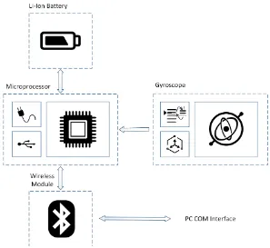
transmission rates of 1 MBit/s. The chosen device was the Adafruit EZ-Link which is capable of opening a Communication port (COM). By combining these components on a single printed circuit board, we finalized the design for a DMP based sensor. Fig. 3 shows the block diagram of a so called Bluefruit sensor. The micro USB port on the Feather can be used for charging the battery and flash the system firmware.
Fig. 3. Bluefruit sensor block diagram. On the right-hand side the gyroscope with included interrupt pin and Accelerometer can be seen. DMP data will be send to the microprocessor which is connected to a Li-Ion Battery (top) and a wireless module (bottom). Charging electronics and a USB connection are integrated on
the microprocessor board.
4.2.
Bluefruit Firmware
To fulfil the performance requirements mentioned in section 4.1 a fast firmware needs to do its job and therefore is the usage of hardware interrupts a crucial factor. These interrupts are rare, because they need many additional circuits and all of the pins are occupied in our application by communication buses already. The only way to still use interrupt routines are so called Pin Change Interrupts (PCINT). These interrupts get triggered by any logic level change on the whole port, which means that up to 8 pins can trigger this event. By defining a port mask, only interrupts on the chosen port will be executed and the rest will be discarded.
behaviour within the main loop and a notification will be sent over the available communication channel.
DMP data is sent as a binary coded quaternion (Shoemake, 1985) to prevent performance loss through
string parsing operations.
4.3.
Unity Software
As mentioned in subsection 3.1 the Biking Simulator uses Unity as its 3D engine. Hence provided tools by the Unity ecosystem are used in our software. The Serial communication part is written in plain C# and does not need any Unity related components. Furthermore, this part needs the full .NET 2.0 framework and not just the (by Unity default) .NET 2.0 subset. This limits the compatibility to other platforms than Microsoft Windows, which is no issue due to HTC Vive minimum system requirements (HTC, 2016). Serial communication gets started by Unity if external hardware needs it. It runs in its own thread and communicates over two queues, one for incoming and the other for outgoing communication. The Serial framework receives data as a byte stream which needs to be interpreted.
Fig. 4. Bluefruit firmware flow diagram.
The data receives a header and gets enqueued. Unity, on the other side, is dequeuing data and uses it to update animations such as pedal movement and wheel spinning. The whole procedure is an implementation of the Producer-Consumer Pattern (Bjork & Holopainen, 2006).
As mentioned in 3.2 we are tracking rotations. To get useful angles the data needs to be prepared. As a first step, we need to translate the rotation of a tracked object into its local space. The reason behind this is the direction of the physical bike itself. The simulator should still work after turning the bike. Hence, we define a reference quaternion, which is the first incoming data from a sensor. All following incoming quaternions can be translated with the following equations:
𝑄 = 𝑞0+ 𝒊𝑞1+ 𝒋𝑞2+ 𝒌𝑞3 (1)
𝑄
−1=
𝑞0−𝒊𝑞1−𝒋𝑞2−𝒌𝑞3𝑞02+𝑞12+𝑞22+𝑞32
(2)
𝑇 = 𝑄 ∗ 𝑅 = 𝑡0+ 𝒊𝑡1+ 𝒋𝑡2+ 𝒌𝑡3 (3)
where
𝑡0= ( 0𝑞0 1𝑞1 2𝑞2 3𝑞3)
𝑡1= ( 0𝑞1+ 1𝑞0 2𝑞3+ 3𝑞2)
𝑡2= ( 0𝑞2+ 1𝑞3+ 2𝑞0 3𝑞1)
𝑡3= ( 0𝑞3 1𝑞2+ 2𝑞1+ 3𝑞0)
and
𝑡 𝒊 = 𝑞 𝒋 ∗ 𝒌 = ( 𝒋 ∗ 𝑞 𝒌) 𝑡 𝒋 = 𝑞 𝒌 ∗ 𝒊 = ( 𝒌 ∗ 𝑞 𝒊) 𝑡 𝒌 = 𝑞 𝒊 ∗ 𝒋 = ( 𝒊 ∗ 𝑞 𝒋)
𝒊 ∗ 𝒊 = 𝒋 ∗ 𝒋 = 𝒌 ∗ 𝒌 =
𝑄
= (𝑄
)
−1∗ 𝑄
(4)Note that this operation is non-commutative and therefore the factors need to stay in the right order. i, j and k are imaginary components, hence the multiplication of those results to -1.
Every sensor rotates around a specific axis in its local space. To find this axis we visualised Qlocal by setting it to the Transform component of a random mesh. By rotating the actual sensor a clear rotation around one axis gets visible. Depending on the chosen axis different computation need to be done. Listing 1 shows this behaviour.
1 if (sensorAxis == RotationAxis.X)
2 {
3 Vector3 v = q * Vector3.forward;
4 angle = Mathf.Atan2(v.y, v.z);
5 }
6 else if (sensorAxis == RotationAxis.Y)
7 {
8 Vector3 v = q * Vector3.forward;
9 angle = Mathf.Atan2(v.x, v.z);
10 }
11 else if (sensorAxis == RotationAxis.Z)
12 {
13 Vector3 v = q * Vector3.up;
14 angle = Mathf.Atan2(v.x, v.y);
15 }
As seen on line 4, 9 and 14 in Listing 1, we always use the vector components which are axis independent to calculate the rotation. Another point is that at least one component of the multiplied vector needs to be axis independent, hence on line 13, the up-Vector instead of the forward-Vector is chosen. The reason behind these two constrains is a simple one, imagine the rotation around the specified axis. A plane which has the specified axis as its normal, is defined by two other axes. By rotating around the specified axis the vector components of the two other axes change. Hence, we need to extract the rotation out of the two components which are dependent to this plane. The whole code is available on GitHub under MIT license (EngagingMobility, 2017).
4.4.
Signal Data Smoothing Methods
After retrieving all absolute angles the animations and other movements can be updated. Due to the fact that the sensors send data asynchronous and suffer from typical problems like drifting, some smoothing algorithms need to be used. This is an important factor against motion sickness, twitchy movements are not natural and enhance indisposition.
Fig. 5. Sensor signals with ten samples on the left, with 20 samples on the right hand side. Top to bottom, raw input signal without smoothing, median filter which still has spikes, average filter which works fine.
A typical input signal is visible on the top in Fig. 5. The amplitude often falls to zero and raises again to a doubled or even tripled mean value. This can be explained by the frame rate of the Unity application. When no sensor data is available within two or three frames, then the angle between those frames will be zero. In the next available data frame, the value of the angle adds all the missing angles. The amount of high frequencies in the raw signal is simply too high to use it directly for movement calculation.
To overcome this problem, we tried two methods with different settings:
Median filtering: By looking at the raw signal at the top region of Fig. 5, we can see that in between of those spikes we often have the actual needed amplitude. Hence, we take the median, if the number of samples is even we define the median as mean between the two middle values. Given the premise that positive and negative spikes have the same probability of appearance, the actual amplitude has to be in the between. As we can see in the middle curve of Fig. 5, the results were not very satisfying. Taken ten samples a lot peaks were unfiltered because more positive than negative peaks occurred in the raw signal. This problem minimizes with more samples but never totally disappears.
that the average of the last n samples should not alter drastically. This assumption turned out working quite well which is visible in the bottom curve of Fig. 5. The principle works like a typical low pass filter, more samples reduce high frequencies.
5.
Performance
In this section, we deal with response times, delays and performance trade-offs. In the first subsection, we talk about the response times of our Bluefruit sensors, followed by a discussion about performance versus quality.
5.1.
Sensor Response Times
The last biking simulator prototype built by Atlantis Games (Breda, 2015) had an input lag of up to two seconds because of the internal hardware design of the Elite Axiom. This was a great issue and needed to be improved. Especially during the breaking process, where reaction time is essential, two seconds are not sufficient.
The reaction times of our Bluefruit sensors are shown in the table below:
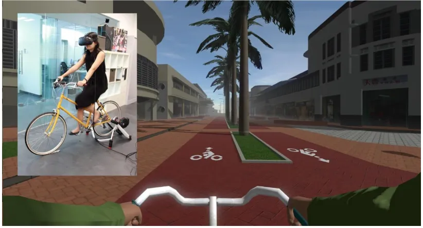
Fig. 6. In game view of the bicycle simulator. Redesigned scenario with biking lanes in Tiong Bahru - Singapore. In the left half is the physical bicycle with a user wearing a head mounted display.
Table 1. Cycling Simulator Performance Data: Bluefruit vs. Elite Axiom
Typical Min Max Elite Axiom
Response Delay [ms] 80 65 100 Up to 2000
Data frequency [Hz] 68 63 74 ~60
Considered this data we achieve up to 30 times lower delay than previous implementations. The number of delivered valid quaternions per second is 68, which is high enough. The sensor operates with a bit rate of 19200bit/s, even better performance can be achieved by increasing this up to to 57600bit/s (maximum numbers in Table 1). Note that the error rate also increases with the transmission speed in the 2.4GHz frequency spectrum. Hence the rate of 19,200bit/s is a good trade-off between speed and transmission errors.
We introduced two smoothing algorithms in section 4.4. Results were shown with 10 and 20 samples, which taken the video frequency of 90Hz (HTC Vive), correspond to ~111 and ~222 milliseconds. Both smoothing algorithms can be implemented very efficiently and therefore just the number of samples are important. The best example is the breaking mechanism. If you immediately decrease the speed from 30 kmh-1 to 0 kmh-1, the bike will take the chosen n samples in frames to stop. It is anyway not realistic that a bike stops that drastically, hence ~222ms are not much and need to be extended by additional braking time. On the other side if the bike would brake immediately because of extremely low speeds the delay could be felt by participants.
6.
Limitations
As mentioned in chapter 2.3, the lack of physical forces increases the probability of getting motion sick. Braking and accelerating feels strange or can make the user sick because of a conflict of vestibular and visual senses. A hydraulic platform which simulates physical forces would help to decrease this issue. How much effort is needed to implement such a platform is despite of the tricky bicycle physics not known. Maybe it would be infeasible to overcome the problems of motion sickness. Physical resistance is the next problem of the current implementation. The Elite Axiom bike trainer reacts way to slow, in worst case up to ~7s, to adjust the pedalling resistance. Furthermore, it cannot accelerate the wheel, which is a problem when the bike is driving downhill in the virtual environment. While going downhill the physical wheel stops because the participant does not have to pedal to moving forward. When the participant then tries to brake, the breaking is not recognized as the wheels are standing still. Hence to create a more realistic simulation the wheel needs to be accelerated by an engine and limited by a real-time resistance unit. Another approach is to install a sensor at the brake to solve the downhill drive problem. The disadvantage of this would be that the wheel “ticking” noise would be missing or needed to be simulated by software.
7.
Conclusion
We show a possible way to build a state of the art bicycle simulator with reasonably priced and commercially available hardware. We talk about the problems of modern Virtual Reality systems and describe how motion sickness occurs. With this information in mind, we present fast Digital Motion Processor based sensors for tracking purposes. Program code is provided which makes all sensor data usable in the Unity game engine environment. In game scenes and the actual physical simulator is shown in fig. 6.
On the other hand, many functions can be added to our present system. A hydraulic platform which provides force feedback would address the issues of motion sickness, and a system which is capable of accelerating and decelerating the wheel in real time would improve functionality of the Bicycle controller. Our future plans with the simulator include the integration of the controller and traffic simulation in a game play that is designed to study cognitive processes and behavioural reactions while cycling in different street design and traffic level scenarios. To this end, we also will enhance the current set-up with audio and human body sensor measurements.
Acknowledgment
References
[1] Simpson, D. M. (2001). Virtual reality and urban simulation in planning: A literature review and topical bibliography. Journal of Planning Literature, 15, 359-376.
[2] Wissen Hayek, U., Waltisberg, D., Philipp, N., & Regamey, G. A. (2016). Exploring issues of immersive virtual landscapes for participatory spatial planning support. Journal of Digital Landscape Architecture, 1, 100-108.
[3] (2017). Engaging mobility. Engaging Mobility Github Repositoy.
[4] Schulzyk, O., Bongartz, J., Bildhauer, T., Hartmann U., & Herpers, R. (2008). A real bicycle simulator in a virtual reality environment: The FIVIS project. Proceedings of the 4th European Conference of the International Federation on Medical and Biological Engineering (IFMBE 08).
[5] Mestre, D. R., Dagonneau, V., & Mercier, C. S. (2011). Does virtual reality enhance exercise performance, enjoyment, and dissociation? An exploratory study on a stationary bike apparatus. Presence, 20, 1-14. [6] Ranky, R., Sivak, M., Lewis, J., Gade, V., Deutsch, J. E., & Mavroidis, C. (2010). VRACK — Virtual reality
augmented cycling kit: Design and validation. Proceedings of IEEE Virtual Reality Conference (VR). [7] Hurwitz, D. D. S. (2015). Bicycling Simulator.
[8] Kim, J. H., Thang, N. D., & Kim, T. S. (2009). 3-d hand motion tracking and gesture recognition using a data glove. Proceedings of IEEE International Symposium on Industrial Electronics.
[9] Breda, A. G. (2015). CYCLESPACES.
[10]Insight, N. H. T. V. (2015). Atlantis Games Presents: Cyclespaces. [11]Nvidia. (2016). Virtual Reality Technology.
[12]Nvidia. (2016). Pascal and VRWorks Infuse VR with New Level of Presence. [13](2016). AMD LiquidVR™ Technology for Developers.
[14](2016). NVIDIA, Lens Matched Shading and Unreal Engine 4 Integration Part 1.
[15]Jr, L. A. J. J. (2000). A discussion of cybersickness in virtual environments. ACM SIGCHI Bulletin, 32, 47-56.
[16]Shoemake, K. (1985). Animating rotation with quaternion curves. ACM SIGGRAPH Computer Graphics. [17](2016). HTC, HTC VIVE Minimal System Requirements.
[18]Bjork, S., & Holopainen, J. (2006). Games and design patterns.The Game Design Reader, 410-437.
Filip Schramka is a computer scientist who is currently working as a research assistant at the Institute for 4D Technologies at FHNW. His main interests are computer graphics, digital image processing, human interaction in virtual spaces, low level programmingand hardware development. After he did his apprenticeship as an electronics technician at the Asea Brown Boveri (ABB) in Baden Switzerland, he obtained his bachelor’sdegree in computer science at the university of applied sciences north-western Switzerland FHNW. Then he started his master’sdegree at the same university. During his master studies,he went abroad to work at the Future Cities Laboratory (FCL) in Singapore where he was working on virtual reality simulation and computer graphics projects.
on combining principles from computer graphics, digital media, and human-computerinteraction and to apply them to a variety of fields such as architectural and urban modelling, digital art and entertainment, or digital media authoring.
Michael Joos is a software engineer specialising in real-time 3D applications. During his university years, he took an internship at SIEMENS’ Corporate Technology R&D department in Munich, where he first started to develop 3D interactive applications. After finishing his studies, he took on the role of software engineer for the video games industry for nearly 10 years. He has also taught computer science courses at the DigiPen Institute of Technology, and worked for a social media company as a full stack engineer. Given his experience with interactive virtual 3D environments, he helps the different teams at the future cities laboratory with their project requirements, such as generating 3D visualisations of heat emissions for the cooler calmerSingapore project, develop a cycling virtual-reality simulator with the engaging mobility team, and guide and mentor computer science interns.