A Synchronous Reference Frame Theory-Space
Vector Modulation (SRF – SPVM) based Active
Power Filter for Mitigation of Current Harmonics
in Distribution System
T. Pavithra
M.E Student
Department of Power Systems Engineering
KIT-KalaignarKarunanidhi Institute of Technology Coimbatore, Tamilnadu
Abstract
This paper presents a shunt active filter for non-linear loads and unbalanced non-linear loads designed to minimize the harmonics present in the three phase three wire system. Due to the large proliferation of power electronic control systems in our day to day life, the switching of these power electronic circuits induces harmonics in the source which causes undesirable effects on the electrical components. Shunt active filter is a harmonic mitigating device comprising of voltage source inverter fed through a DC capacitor. The control strategy is based on extraction of harmonics using synchronous reference frame theory. The extracted harmonics are used to generate PWM signals using the Space Vector Pulse Width Modulation (SVPWM) for the voltage source inverter (VSI) which has reduced losses. The proposed method has been modeled and simulated using Matlab / Simulink and the output shows that the Total Harmonic Distortion (THD) of the supply has been reduced at the Point of Common Coupling (PCC).
Keywords: Harmonics, Synchronous Reference Frame (SRF) theory, SVPWM, THD
________________________________________________________________________________________________________
I. INTRODUCTION
With the increase in non -linear loads and unbalanced non-linear loads the quality of power delivered to the load is getting distorted because of the use of large number of power electronic switches which are used to control these non-linear loads. The quality of power directly affects the electrical utilities and the losses in these systems are increased due to the distorted power. The various power quality problems are voltage sag, swell, spike, flicker, and harmonics. Various solutions are provided to improve the quality of power delivered to the load. Harmonics present in the system can be reduced by passive filters or active filters. Passive filters are designed using inductors and capacitors which can be connected in series, shunt or hybrid. Passive filters eliminate harmonics of a particular order for which it is tuned and the other harmonics remain in the system. The use of The L-C filters makes the system bulky and causes resonance with other circuit elements in the network. To overcome these drawbacks active filters were developed.
An active power filter (APF), with its strong ability in dealing with harmonics current, is considered as the most effective and attractive solution in the field of power quality improvement. Compared with the passive filter (PF), the APF presents advantages such as being avoidable for potential resonance, flexible in control, accurate in parameter design, and small in size. The active filter eliminates harmonics of any order and compensates both voltage and current harmonics present in the system. The series active filter is used to compensate the voltage related harmonics and the shunt active filter is used for the elimination of current related harmonics. The shunt active filter comprises of two main stages, the first stage is the detection of harmonics by means of a suitable technique and the second stage is the generation of PWM signals for the VSI circuit. The harmonics in the source are extracted from to create these components, incorporating the applicable criteria that follow.
The fundamental component by means of different methods as discussed in [2]–[5]. In this paper the synchronous reference frame theory is used for harmonic detection from the fundamental component of the sinusoidal signal of the source. The extracted harmonics are separated from the fundamental by means of a high pass filter.
With reference to the harmonics that are extracted compensation signals are generated by the voltage source inverter. For the control of compensation signals in the VSI the
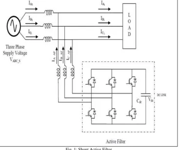
Fig. 1: Shunt Active Filter
IABC_S represents the source current and VABC’S represents the source voltage of the three phases. The active filter is connected to the lines through coupling reactors [7]-[8]. The coupling inductor is used to reduce the current harmonics generated by the inverter and the capacitor keeps the dc voltage ripple factor low
III. CONTROL ALGORITHM FOR HARMONIC DETECTION
The stationary reference frame quantities are transformed in to synchronously rotating reference frame using cosine and sine function. The components ILd and ILq represent the direct and quadrature component of the distorted current. The d-q component rotates synchronously with the supply voltage. The‘d’ Coordinate corresponds to the positive sequence current and the ‘q’ component corresponds to the negative and ‘0’ represents the zero sequence components. The currents ILd and ILq comprises of average component and the oscillating component of the currents.
Fig. 1: block diagram of SRF-SVPWM for mitigation of harmonics IV. SIMULATION RESULTS
The simulation result of shunt active filter is Simulated using MATLAB/SIMULINK.The system is designed for a 400V AC source feeding a non- linear load having a resistance R=4Ω, DC link capacitor C= 300µF, frequency f=50HZ. The active filter is switched ON by using a switch after a time interval of 0.2 second to study the variation of source current under varying load conditions 3 phase AC NON-LINEAR LOAD AND UNBALANCED NON-LINEAR LOAD
abc to αβ transformation
Iα Iβ
TO
Id Iq 2ndorder high pass
filter
Id Iq TO Iah Ibh
dq to abc SVPWM Voltage source inverter DC link capacitor Error signal IA -AF IB -AF IC -AF
IA - L IB - L IC - L
IA BC -AF GATE PULSE IA-S IB-S IC-S
BLOCK DIAGRAM OF SRF-SVPWM FOR MITIGATION OF HARMONICS
Fig.1 block diagram of SRF-SVPWM for mitigation of harmonics
Fig .6: grid current
The plot shown in Fig.6 shows the source current in Amps Vs Time and in this plot it is seen that due to the switchingof the load after 0.2 second the current is getting compensated
Fig. 7: load current
The plot shown in Fig.7 gives the load current characteristics. Due to the non-linear load the current is non-sinusoidal. The non-sinusoidal currents distort the supply currents injecting harmonics into the system.
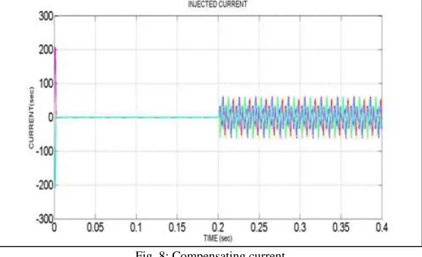
Fig. 8: Compensating current
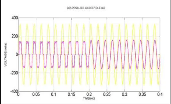
Fig. 9: compensated source voltage The plot shown in Fig. 9 shows the compensated source voltage at PCC
The plot in Fig 10 shows the plot between source voltage and the source current at the point of common coupling. The plot shows that the load current is distorted because of the nonlinear load and supply current remains purely sinusoidal after 0.2 seconds due to the cancellation of harmonics by the shunt active filter.
Fig. 10: source current versus load current
The plot shown in Fig.11 shows the source current versus load current. Due to the shunt active filter and due to the cancellation of harmonics the supply is sinusoidal and free from harmonics after 0.2 seconds
Table – 1
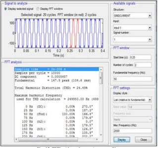
THD Values of three phases with and without Shunt active filter. phases Without Filter With Filter
R Phase 24.48% 0.97 % Y Phase 24.49% 1.00 % B Phase 24.49 % 1.00 %
In Table 1 the THD values of the three phases are measured with and without shunt active filter. With the addition of shunt active filter the THD value is reduced.
REFERENCES
[1] YanjunZhang,Yu Li, WendaZhan,WenjieChen,andJinjun Liu, “A source –current detection shunt active power filter control scheme based on vector
resonant controller”.IEEE Trans. Ind. Appl., vol.50,no.3, May/June2014.
[2] MetinKesler and EnginOzdemir,“Synchronous-Reference-FramBasedControl Method for UPQC Under Unbalanced and Distorted Load Conditions”, IEEE
Trans. Ind. Appl., vol. 88, no. 9, pp. 3967–3975, September 2011.
[3] Akagi, H., ”New trends in active filtersfor improving power quality”, in Proc. of the International Conference on PowerElectronics, Drives and Energy
Systemsfor Industrial Growth, 1996,Vol. 1, Issue 8-11, Jan. 1996, pp. 417 – 425.
[4] GabrioSuperti-Furga and GraziaTodeschini, “Discussion on Instantaneous p–q Strategies for Control of Active Filters ” IEEE Transactions on Power
Electronics, vol. 23, no. 4, July 2008.
[5] Md. AshfanoorKabir and UpalMahbub,” Synchronous Detection and Digital control of Shunt Active Power Filter in Power Quality Improvement”,2011
IEEE.
[6] Rajendra R. Sawant, Member, IEEE, and Mukul C. Chandorkar, Member, IEEE, “A Multifunctional Four-Leg Grid-Connected Compensator”, IEEE
Transactions On Industry Applications, Vol. 45, No. 1, January/February 2009
[7] Oleg Vodyakho, Chris C. Mi, “Three-Level Inverter-Based Shunt Active Power Filter in Three-Phase Three-Wire and Four-Wire Systems” IEEE
Transactions on Power Electronics, Vol 24, No.5., pp. 1350 – 1363, May 2009.
[8] A. D. le Roux, H. du, T. Mouton, and H. Akagi, “Digital control of an integrated series active filter and diode rectifier with voltage regulation,”IEEE Trans.
Ind. Appl., vol. 39, no. 6, pp. 1814–1820, Nov./Dec. 2003.
[9] D. Li, Q. Chen, Z. Jia, and J. Ke, “A novel active power filter with fundamentalmagnetic flux compensation,” IEEE Trans. Power Del., vol. 19, no. 2, pp.
799–805, Apr. 2004.
[10] S. H. Reyes, S. Patricio, and K. Hyosung, “Instantaneous reactive powertheory applied to active power filter compensation: Different
approaches,assessment, and experimental results,” IEEE Trans. Ind. Electron., vol. 55,no. 1, pp. 184–196, Jan. 2008.
[11] A. Chandra, B. Singh, B. N. Singh, and K. Al-Haddad, “An improvedcontrol algorithm of shunt active filter for voltage regulation, harmonicelimination,
power-factor correction, and balancing of nonlinear loads,”IEEE Trans. Power Electron., vol. 15, no. 3, pp. 495–507, May 2000.
[12] J. C. Wu and H. L. Jou, “Simplified control method for the single-phaseactive power filter,” Proc. Inst. Elect. Eng.—Elect. Power Appl., vol. 143,no. 3, pp.
219–224, May 1996.
[13] J. Miret, M. Castilla, J. Matas, and J. M. Guerrero, “Selective harmoniccompensationcontrol for single-phase active power filter with high