R E S E A R C H
Open Access
United Reference Method for
three-dimensional treatment evaluation
Shereef Shahen
1, Manuel O. Lagravère
2, Gennaro Carrino
1, Fady Fahim
3, Reham Abdelsalam
4,
Carlos Flores-Mir
5and Letizia Perillo
6*Abstract
Background:Reproducible and descriptive Three-dimensional treatment evaluation can enhance future treatment based on realistic results. So, the purpose of this study was to describe a new method for three-dimensional treatment evaluation showing how to use fully-automated craniofacial superimposition of CBCT records combined with reference system to obtain descriptive and comparable results. This new method was named United Reference Method (URM). Methods:URM is a combination of automated 3D superimposition on anterior cranial base surface anatomy and
measurements based on reference system. It was developed to show how to use fully-automated superimposition to obtain descriptive numerical comparable values. The method is based on: one main reference system for both superimposed CBCT records, semi-automation to increase accuracy, all measurements are projections and auxiliary references to aid in landmarks identification and measurements.
The method steps can be described following a four-step approach: (1) Superimposition performed through a fully automated, voxel-wise, rigid registration considering only cranial base as a stable structure; (2) Identification of reference landmarks once on the superimposed records for corrected Frankfort Horizontal plane (C-FH) construction and a new semi-automated constructed Sella point to correct Orbital asymmetry; (3) Head orientation of superimposed CBCT images based on the C-FH; (4) Identification of landmarks affected by treatment with the aid of auxiliary reference planes. Evaluation of linear or angular changes derived by projection of same pre- and treatment landmarks on the C-FH. Pre- and post-expansion CBCT scans of 20 unilateral cleft lip and palate patients were used to calculate intra and inter-rater reliability. (X, Y and Z) coordinates, mean, standard deviation (SD) and Intra-class Correlation Coefficient (ICC) were calculated.
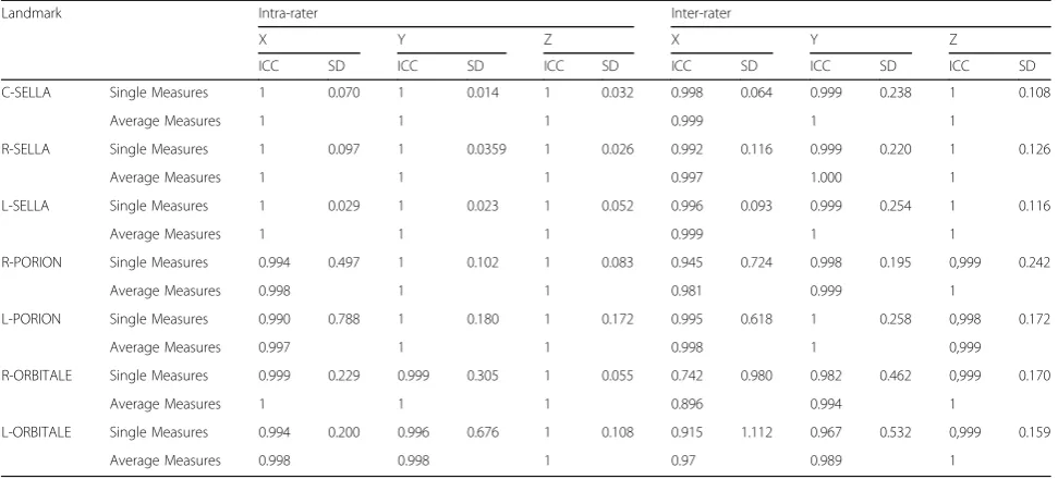
Results:The proposed coordinates for C-FH construction showed ICC≥0.998 and SD ranging from 0.064 to 0.242 mm. On the other hand, excluded coordinates due to expected natural craniofacial asymmetry had the lowest reliability ICC≥0.742 and SD dramatically increased up to 1.112 mm.
Conclusion:URM showed adequate reliability so it can be used to produce three-dimensional descriptive data of craniofacial structural changes.
Keywords:Three-dimensional treatment evaluation, Descriptive three-dimensional superimposition, Three-dimensional reference system, Semi-automated landmarks
* Correspondence:[email protected]
6Head of Orthodontic Division and Chair of the Postgraduate Orthodontic
Program, Department of Orthodontics, University of Campania Luigi Vanvitelli, Via L. De Crecchio 6, 80138 Naples, Italy
Full list of author information is available at the end of the article
Background
Reproducible and descriptive treatment evaluation can pro-vide realistic results. The obtained information can enhance future treatment. So, record as lateral cephalometric radiog-raphy was used for orthodontic diagnosis and treatment planning [1]. Although helpful, this imaging modality, it is a two-dimensional (2D) representation of a three-dimensional (3D) object and thus has several limitations, including errors in projection, distortion and structural superimposition, espe-cially when used to evaluate skeletal and dental changes dur-ing treatment and/or growth. Despite these drawbacks, 2D records have been used over the last 80 years for superim-position and treatment change evaluation based on best fit of cranial base structures.
With the introduction of 3D imaging tools such as dental cone-beam computed tomography (CBCT), most limita-tions in 2D imaging have been theoretically overcome [2]. Many research groups have been developing 3D analysis based on CBCT superimposition to analyze treatment and/ or growth changes [3–7]. Currently, two main methods de-veloped by two different research groups are used to super-impose CBCT images. One group designed an optimization algorithm landmark-based superimposition approach [3]. This method identifies several landmarks to create a 3D coordinate reference system. Although effect-ive, it presents several limitations such as errors made by the operator in locating the initial landmarks. The second group used a software voxel-based superimposition method with the best fit of the cranial base structures with high accuracy [4–6]. However, when using this approach, the descriptive amount and the spatial direction of changes are difficult to interpret. The main trend in the literature [2–6] was always to check 3D superimposition accuracy rather than to show how to use fully-automated superimposition to obtain descriptive numerical comparable values.
The aim of this study was to describe a new method for three-dimensional treatment evaluation showing how to use fully-automated craniofacial superimposition of CBCT records combined with reference system to obtain descrip-tive and comparable results. This new method was named United Reference Method (URM).
Methods
Ethical approval was obtained from both of University of Campania“Luigi Vanvitelli”(Naples, Italy; approval number 1394/18) and Faculty of Oral & Dental Medicine, Cairo University (Cairo, Egypt; approval number 16/12/21).
URM is a combination of automated 3D superimpos-ition on anterior cranial base surface anatomy and mea-surements based on reference system. The four-step URM approach as follows:
Step 1–Superimposition
Pre- and post-treatment CBCT scans were obtained using the same machine [8], parameters, x-ray intensity, imaging time and voxel size. In this study, SCANORA®3D (Sore-dex-Nahkelantie160, Tuusula, Finland) was used at 15 MA, 85 KV and 20 s exposure time. Digital Imaging and Com-munication of Medicine (DICOM) images were generated and exported with the same thickness (0.35), bit-depth (16) and dimensions (414X414 mm). The DICOM files were imported into Viewbox 4.0.1.7 software (dHAL Software, Kifissia, Greece, Athens) which has Computer-aided design (CAD) tools. 2D slices were assembled into volumes, subse-quently converted into triangular mesh surface models created from the voxel data [4,5,9]. A different color was given to each record.
The pre- and post-treatment CBCT scans were super-imposed using structures not displaced or changed dur-ing craniofacial growth or orthodontic treatment. This superimposition was performed using a fully automated, voxel-wise, rigid registration in the cranial base [4, 5, 10–13]. Cranial base registration was obtained by maxi-mizing mutual voxel information from pre- and post-treatment CBCT images to avoid inevitable observer-dependent error when using techniques based on over-lap of anatomic landmarks [4].
As this superimposition depends on masking or eliminat-ing structures that may be affected by treatment or growth, so that the software searched only in cranial base struc-tures. Leaving other structures, affected by treatment and/ or growth changes, would otherwise increase the working time required by the software to search for all available possibilities to find the best match [4, 5]. The structures used as reference for the cranial base included anterior part of hypophyseal fossa, wings of spenoid, crista galli. The soft-ware provides tools to select 3D zone useful for superim-position in order to exclude parts subjected to change. Reproducibility of this masking method was already reported in literature [4,5,14].
After superimposition was completed, maxillary and man-dibular structures were unmasked. The two CBCT scans were then recorded as linked files and treated as one.Some parts of the two CBCT images appeared fused and indistin-guishable, suggesting the high quality of the automated superimposition whereas the non-fused parts indicated changes. Mesh images are necessary for superimposition, later any 3D display (multiplanar reconstruction, direct vol-ume rendering, isosurface and mesh) can be used.
Step 2–Reference landmark identification
The C-FH was constructed from four points: right and left Porion points, and right and left C-Orbitale points and midline was defined by C-Sella and Porion axis to correct Frankfort Horizontal (FH) midline (Figs. 1 and 2). C-FH was used for head orientation and to produce projection measurements describing numerically direction of changes whereas it was not used for superimposition, which is fully-automated.
Step 3–Head orientation
After locating reference landmarks, the superimposed CBCT scans were reoriented to make C-FH horizontal using the software. Orientation was required at this point to create new coordinate system with zero point at the center of C-FH in addition to standardize the 3D view and to reduce errors in identifying landmarks necessary for assessing changes [15,17].
Step 4–Identification of landmarks for evaluating changes
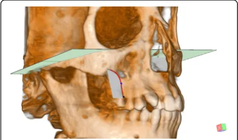
Landmarks to determine 3D skeletal and dental changes in Table 2 during treatment or growth were identified on the reoriented CBCT images with the aid of auxiliary refer-ence planes the mid-maxillary perpendicular plane was constructed cutting the maxilla perpendicularly to the C-FH midway between ANS and PNS points. R- and L-Max can be digitized semi-automatically by manual tra-cing of the right and left maxillary cortical bone on a cut at the level of Mid Max Perpendicular plane level. The most concave point was automatically digitized at the nearest point to the midline in relation to C-FH (Fig. 3). These landmarks need to be located twice and only after head orientation (step 3), unlike reference landmarks previously identified once in step 2.
Linear and angular measurements obtained from the same points identified in pre- and post-treatment CBCT images, (e.g., pre-and post-treatment R- and L-Max), were projected in a direction parallel or perpendicular to C-FH (Fig.4). To show how to evaluate linear and angu-lar changes after expansion treatment of cleft patients using URM, pre- and post-expansion (after 6 months) CBCT images of 20 unilateral cleft lip and palate
Table 1Landmark definition for use in reference system
Landmark Definition
Right Sella and Left Sella (R- and L Sella)
Points in the center of the right and left 3D borders of the Hypophyseal fossa. Points are digitized semi-automatically through manual tracing of the right and left borders of the Hypophyseal fossa and then automatically digitized by the software. (Fig.1)
Semi-automated Constructed Sella (C-Sella)
A constructed semi-automated point that lies midway between right and left Sella. (Fig.1)
Porion (Po) The most superior midpoint of each external acoustic meatus.
Porion axis A line passing between the two
Porion points. (Fig.2)
Orbitale (Or) The most inferior point of each infra-orbital rim.
Mid-Orbitale A point midway between the two
Orbitale points. (Fig.2)
Right and Left Constructed Orbitale (C-Orbitale)
Points at the level of mid-Orbitale point superior-inferiorly (Z coordinate) and lies at equal distances medio-lateraly from the C-Sella point (X coordinate), in a parallel direction to the Porion axis (Y coordinates). (Fig.2)
Fig. 1Constructing R-and L-Sella: 1, R-Sella; 2, Hypophyseal fossa; 3, L-Sella; 4, C-Sella. Red line: Sella border
patients (mean age of 20 years ranging between 18 and 25) were collected from the archives of Department of Orthodontics, Cairo University, Cairo, Egypt. The ALARA principle (radiation dose‘As Low As Reasonably Achievable’) was respected. Post-expansion CBCT records, required to evaluate the cleft space for the alveolar bone grafting, were also useful to measure the achieved expansion in the cleft patients. Measurement definitions were reported in Table 3. All previous steps were to explain to developers but actual steps carried out by the users are: first masks structures may be af-fected by treatment then click superimposition, second identifies reference points R-L Sella, R-L Porion and R-L Orbitale, third click to orient superimposed pre- and post-treatment CBCTs. Fourth identify points affected by treatment then save results.
Reliability of landmark location and CBCT orientation
The obtained CBCT records were used also to calculate intra- and inter-rater reliability for C-FH. R-L Sella, C-Sella, R-L Po and R-L Orbitale were identified three times at weekly intervals by three observers (SS, FF, RA).
Three-dimensional coordinates (X, Y and Z based on the original volume coordinate system before orientation) were exported to an Excel spreadsheet before carrying out a statistical analysis. Mean, standard deviation (SD) and Intraclass Correlation Coefficient (ICC) were calculated to evaluate the reproducibility of the newly C-FH but not the automated-superimposition which was already proven to be accurate [4–6].
Results
Three coordinates (X, Y and Z coordinates) were needed to determine the spatial position of each point. Constructed Orbitale point was identified based on Z coordinate of mid-Orbitale point, X coordinate of C-Sella and Y direction of Porion. The following coordinates: X coordinate of C-Sella, Z coordinates of Porion and Orbitale, Y coordinate of Porion, used to construct C-FH and correct natural cra-niofacial asymmetry had good reliability: ICC≥0.998 (Table4, Figs. 1 and2). On the other hand, the excluded coordinates due to expected natural craniofacial asymmetry (X coordinates of Porion and Orbitale and Y coordinate of
Table 2Landmark definition for structures affected by treatment
Landmark Definition
ANS The most anterior midpoint of the anterior nasal spine of the maxilla.
PNS The most posterior midpoint of the posterior nasal spine of the palatine bone.
R-Max and L-Max The Most concave point on the maxillary basal bone on the Mid-Max.
Perpendicular plane. (Fig.3)
R- Alveo and L- Alveo
The most inferior point of the alveolar crest on the Mid-Max.
Perpendicular plane. (Fig.3)
Molar axis The line perpendicular on the plane constructed from the three molar root apices.
Premolar axis The line from the buccal cusp tip to the apex of buccal root of the upper first premolar.
Fig. 3Maxillary basal bone. Red curve shows cut at Mid-Max. Perpendicular plane. Blue point is R-Max. Black point is R-ALV
Fig. 4Distance traveled by R- Max mediolaterally. Green point: Pre-expansion R-Max & L-Max. blue point: Post Pre-expansion R-Max & L-Max
Table 3Definition of measurements for structures affected by treatment
Parameters Definition
Linear Measurements (mm)
R-Max and L-Max
Distance traveled by Max mediolaterally. (Fig.4)
R-Cres and L-Cres
Distance traveled by Alveo mediolaterally.
Angular Measurements (°)
R-ALV and L-ALV
Angular change between pre and post lines from Max to Alveo projected on Mid Max Perpendicular plane, perpendicular to C-FH.
R-Pre and L-Pre
Angular change between pre and post premolar axes projected on Mid Max Perpendicular plane, perpendicular to C-FH.
R-6 and L-6
Orbitale) had the lowest reliability: ICC≥0.742 and ICC≥ 0.967, respectively.
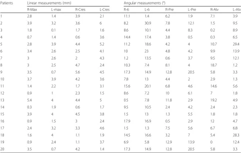
The proposed coordinates showed standard deviations ranging from 0.064 mm in X coordinate of C-Sella to 0.242 mm in Z coordinate of Porion. In addition, Z was the only proposed coordinate of Orbitale with a standard devi-ation ranging from 0.055 mm to 0.170 mm while the stand-ard deviation of excluded coordinates dramatically increased up to 1.112 mm as in X coordinate of Orbitale (Table 4, Figs. 1 and 2). The linear and angular changes after expansion treatment of the unilateral cleft lip and palate patients are shown in Appendix1.
Discussion
During the last decades, superimposition based on either landmarks or structures has been used to visualize craniofa-cial changes. After reaching adequate accuracy level following automation of 3D structural superimposition, these changes can now be quantified and described three-dimensionally. However, this process is challenging and prone to many errors [4,5,14]. This study proposes a more effective way to use automated superimposition to describe 3D changes. Some Authors used teeth as references [18–20], but teeth can move and are thus unreliable landmarks. To overcome this issue, stable references that do not change during growth and/or orthodontic treatment were selected [3].
Skeletal landmarks should be carefully selected to avoid unreliable reference landmarks located in anatomical struc-tures subject to growth or treatment effects [3]. It has been suggested that cranial base landmarks located in anatomic-ally stable structures can be identified from CBCT imaging with very good reliability, although it can be argued that
more than 85% of cranial base growth is completed by age of five [3].
Another technical error is the use of direct measurements, such as the distance between two landmarks, which are un-able to give information about the direction of changes [18, 19]. Such data can be obtained using the URM by projecting the measurements on a C-FH reference plane [17].
Currently, two main methods are routinely utilized to evaluate 3D treatment changes. The first method [5,14] uses automatic voxel-based superimposition and changes are visualized by different color depictions indicating different changes. Although this method was proven to be reprodu-cible [4–6,21], it still presents some limitations as it can only produce direct measurements and thus no descriptive results [17]. Moreover, superimposition can only be used to com-pare pre- and post-treatment records of the same patient. It does not allow comparison of data derived from different patients due to the lack of a common reference system [7]. The second method [20] uses a reference system identified twice, once for pre- and once for post-CBCT images to take measurements on pre- and post-CBCT scans without super-imposition with the advantage of showing direction of mea-surements. However, this method can likewise be prone to error because the required multiple and repeated landmark identification processes can increase the overall combined possibility of error [21]. Compared to 2D analysis, possible landmark location error increases in 3D analysis due to the presence of a third dimension-coordinate [22].
This study proposes how to use of 3D superimposition combining the advantages of the first and second methods. It was named United Reference Method (URM) because, after automatic superimposition, only one reference system
Table 4Intraclass Correlation Coefficient (ICC) and Standard deviation (SD) of Intra- and Inter- rater reliability error for landmarks digitization of X, Y and Z coordinates for Reference system
Landmark Intra-rater Inter-rater
X Y Z X Y Z
ICC SD ICC SD ICC SD ICC SD ICC SD ICC SD
C-SELLA Single Measures 1 0.070 1 0.014 1 0.032 0.998 0.064 0.999 0.238 1 0.108
Average Measures 1 1 1 0.999 1 1
R-SELLA Single Measures 1 0.097 1 0.0359 1 0.026 0.992 0.116 0.999 0.220 1 0.126
Average Measures 1 1 1 0.997 1.000 1
L-SELLA Single Measures 1 0.029 1 0.023 1 0.052 0.996 0.093 0.999 0.254 1 0.116
Average Measures 1 1 1 0.999 1 1
R-PORION Single Measures 0.994 0.497 1 0.102 1 0.083 0.945 0.724 0.998 0.195 0,999 0.242
Average Measures 0.998 1 1 0.981 0.999 1
L-PORION Single Measures 0.990 0.788 1 0.180 1 0.172 0.995 0.618 1 0.258 0,998 0.172
Average Measures 0.997 1 1 0.998 1 0,999
R-ORBITALE Single Measures 0.999 0.229 0.999 0.305 1 0.055 0.742 0.980 0.982 0.462 0,999 0.170
Average Measures 1 1 1 0.896 0.994 1
L-ORBITALE Single Measures 0.994 0.200 0.996 0.676 1 0.108 0.915 1.112 0.967 0.532 0,999 0.159
is identified once and all the measurements are projected on C-FH after. This does not assume that reference will not change, creating unified coordinate system is the target to compare results between pre- and post-expansion records.
The advantage of digitizing reference landmarks only once is that it eliminates error related to reference. In other words, if an error cannot be avoided, the same error will be made on the superimposed CBCT records. This does not mean that the method is error free, but only that the error related to reference becomes constant and has no effect on evaluated changes. Nevertheless, even using URM, error re-lated to areas affected by growth and/or treatment remains unavoidable since related points are identified twice.
In addition, semi-automation in landmark identification has further advantages. It can help to accurately identify challen-ging points. For example, the Hypophyseal fossa is not a uni-form 3D cavity and so it is difficult to identify a reproducible point in the center without the help of software. Semi-automation can create new 3D points, which were not described before. For instance, the URM allowed for the iden-tification of reproducible skeletal points, such as R- and L-Max-, on the lateral smooth surface of the maxilla (Fig. 3). Semi-automation can also enhance reference reliability utiliz-ing C-Sella, which was shown to be reproducible. C-Sella re-duces the impact of Orbitale asymmetry and corrects FH midline with also the help of Porion axis, improving FH con-struction. The new plane is named C-FH. In contrast, the use of the original Orbitale points could result in poor FH midline and twisted FH (Fig.2). Even though Porion points may have a degree of natural asymmetry [23] this problem could be more obvious in the Orbitale points. It has to be noted that the URM midline was derived from C-Sella independent of X coordinates of Porion and Orbitale points. The generated points are based on low error coordinates only [24].
Another feature of the URM is its different use of slices. Several authors evaluate CBCT using slice direction derived from head orientation during or after imaging without a reliable standardization [17,18]. In addition, the position of these slices is also related to unstable landmarks [17–19] In some 3D studies [1,16,18,19,25,26], head orientation is based on operator evaluation of various structures to obtain a more horizontal slicing direction, whereas reference points are identified later. Thus, head orientation can be subject to a degree of variability and is not linked to subse-quently identified references. Conversely, slice direction in the URM is derived from a standard head orientation obtained from C-FH, and slices linked to the C-FH may en-hance reproducibility of point identification. Furthermore, measurements from 2D slices [18, 19] are combined with 3D display and standardized using a reference plane unaffected by treatment, as previously reported [3].
Some previous studies stated that metallic landmarks identification and cortical bone thickness measurements are not affected by imaging head position [8, 27, 28],
whereas the amount of directional change is strongly influ-enced by head orientation [29].
This difference between the URM and other methods is depicted when evaluating the treatment of expansion cases, where direct measurements on 2D slices from spiral CT [26] were used, and by other papers applying 3D display without any reference [30] or with unstable reference [31, 32]. Semi-automation in URM allowed identification of reprodu-cible skeletal points, such as R- and L-Max on the wide lat-eral surfaces of maxilla where are no sharp 3D skeletal landmarks can be identified. Thus, many researchers were obliged to use dental points to evaluate 3D skeletal expansion [18–20] even though dental points are unreliable landmarks. Conversely, the URM measured mediolateral change by pro-jecting R-and L-Max identified on superimposed pre- and post-CBCT scans on C-FH (Fig. 4) derived from structures unaffected by treatment. In addition, with the URM, only one reading for each measurement was sufficient to produce a descriptive standardized result describing exactly how much basal bone of maxilla moved medio-laterally and in which direction projecting changes on C-FH. Thus, the oper-ator can compare pre-and post-treatment results, simplifying data interpretation.
Limitations
The URM has some limitations although not strictly related to the method but to all CBCT superimposition methods. Generating high quality CBCT images to make reliable superimpositions is still challenging. The same machine with the same imaging parameters for each patient may be more useful. Few imaging manipulation programs offers advanced geometric and CAD features, limiting the use of the URM. Necessity to make pre- and post-treatment CBCT records to perform superimposition.
Although common X-ray effective dose of CBCT was re-duced to 50μSv in comparison to 2000μSv in conventional CT [33], exposure may be still considered an issue to keep exposure to radiation as low as is reasonably achievable (ALARA). This may be justified if CBCT was a substitution of all other radiological exams. “the sum of the effective doses for panoramic and lateral cephalometric and periapical images would be in the same range or even higher than that of CBCT, and still without 3D evaluation.”[34]. In addition, recent technology of Ultra Low Dose (ULD) can even reduce the effective dose to 18μSv for 200 mm3volume [35].
Conclusion
URM showed adequate reliability and could be used to produce three-dimensional descriptive data of craniofacial structural changes.
Abbreviations
2D:Two-dimensional; 3D: Three-dimensional; ALARA: Principle: Radiation dose‘As Low As Reasonably Achievable’; CAD: Computer-aided design; CBCT: Cone-beam computed tomography; C-FH: Corrected Frankfort Horizontal plane; DICOM: Digital Imaging and Communication of Medicine; FH: Frankfort Horizontal; ICC: Intra-class Correlation Coefficient; SD: Standard deviation; URM: United Reference Method
Acknowledgments Not applicable.
Funding
This research did not receive any specific grant from funding agencies in the public, commercial, or not-for-profit sectors.
Availability of data and materials
The data supporting the conclusions of this article are included in tables within the article.
Authors’contributions
SS contributed to conception and design. SS, FF, RA contributed to data acquisition. SS, MOL contributed to data analysis. SS, GC, CFM, LP contributed to data interpretation and drafting of manuscript. SS, MOL, GC, FF, RA, CFM, LP contributed to Revising manuscript critically and gave final approval of the version to be published and Agreed to be accountable for all aspects of the work in ensuring that questions related to the accuracy or integrity of any part of the work are appropriately investigated and resolve. All authors read and approved the final manuscript.
Ethics approval
Ethical approval was obtained from both of University of Campania“Luigi Vanvitelli”(Naples, Italy; approval number 1394/18) and Faculty of Oral & Dental Medicine, Cairo University (Cairo, Egypt; approval number 16/12/21).
Consent for publication
Authors have given their consent for their data to be published in the report.
Competing interests
The authors declare that they have no competing interests.
Publisher’s Note
Springer Nature remains neutral with regard to jurisdictional claims in published maps and institutional affiliations.
Author details 1
Department of Orthodontics, University of Campania Luigi Vanvitelli, Naples, Italy.2Orthodontic Graduate Program, University of Alberta, Edmonton, AB, Canada.3Department of Orthodontics, Cairo University, Cairo, Egypt. 4Department of Orthodontics, Al Azhar University, Cairo, Egypt.5Head of the
Division of Orthodontics and Orthodontic Program Director, Department of Dentistry, University of Alberta, Edmonton, Canada.6Head of Orthodontic Division and Chair of the Postgraduate Orthodontic Program, Department of Orthodontics, University of Campania Luigi Vanvitelli, Via L. De Crecchio 6, 80138 Naples, Italy.
Appendix
Table 5Linear and angular changes after expansion treatment of the unilateral cleft lip and palate patients
Patients Linear measurements (mm) Angular measurements (°)
R-Max L-max R-Cres L-Cres R-6 L-6 R-Pre L-Pre R-Alv L-Alv
1 2.8 1.4 3.9 2.1 11.1 1.4 6.2 1.9 7.1 3.9
2 3.9 3.2 3.6 6 8.2 30.9 7.8 12.1 1.5 9.5
3 1.8 0.1 1.7 1.6 8.6 10.1 4.4 8.3 0.2 8.9
4 0.7 1.4 0.6 3.6 14.4 17.4 3.8 0.5 0.3 6.5
5 2.8 3.9 4.4 5.2 11.2 18.6 4.2 4 10.7 29.4
6 3.4 2.6 2.5 4.1 10 23 4.8 4.2 9.9 13.9
7 3 2.6 2 4.3 1.2 13.5 0.6 3.7 9.5 12.1
8 3 2.5 4.7 2.4 10.3 7.4 8.1 4 18.7 1.2
9 3.5 0.7 5.6 4.5 17.3 14.9 12.8 20.5 5.8 3.3
10 3.7 3.9 4.2 3.6 7.8 13 4.4 2 2.9 1.3
11 1.4 2.2 1.7 3.1 15.6 20.1 6.8 4.6 14.6 5.6
12 0.9 1 2.3 1.5 8.6 7.2 10 6.1 7 1.8
13 5.4 4 4.4 5 0.5 7.8 11.8 2.9 19.2 4.9
14 0.3 1.9 0.6 1.7 9.5 10.5 2.4 4.2 2.4 2.3
15 3.9 4 4.5 3.8 1.5 13 1.3 5.5 1.8 1.8
16 0.9 1.5 3 2.4 17.9 16.9 0.5 2.9 12 4.7
17 2.4 3.2 3.3 4.6 1.5 1.3 7.5 5.6 6.7 6.8
18 1.6 4 1.1 1.9 14.5 16.6 3.2 7 5.4 28.3
19 0.9 2.4 1.1 3.7 6.9 5.8 12.9 13.9 0 12.4
Received: 3 July 2018 Accepted: 25 September 2018
References
1. Park SH, Yu HS, Kim KD, Lee KJ, Baik HS. A proposal for a new analysis of craniofacial morphology by 3-dimensional computed tomography. Am J Orthod Dentofac Orthop. 2006;129:600 e23-34.
2. DeCesare A, Secanell M, Lagravère MO, Carey J. Multiobjective optimization framework for landmark measurement error correction in three-dimensional cephalometric tomography. Dentomaxillofac Radiol. 2013;42:20130035. 3. Lagravère MO, Major PW, Carey J. Sensitivity analysis for plane orientation in
three-dimensional cephalometric analysis based on superimposition of serial cone beam computed tomography images. Dentomaxillofac Radiol. 2010; 39:400–8.
4. Cevidanes LH, Motta A, Proffit WR, Ackerman JL, Styner M. Cranial base superimposition for 3-dimensional evaluation of soft-tissue changes. Am J Orthod Dentofac Orthop. 2010;137:S120–9.
5. Cevidanes LH, Bailey LJ, Tucker GR Jr, Styner MA, Mol A, Phillips CL, Proffit WR, Turvey T. Superimposition of 3D cone-beam CT models of orthognathic surgery patients. Dentomaxillofac Radiol. 2005;34:369–75.
6. Cevidanes LH, Styner MA, Proffit WR. Image analysis and superimposition of 3-dimensional cone-beam computed tomography models. Am J Orthod Dentofac Orthop. 2006;129:611–8.
7. Shahen S, Carrino G, Carrino R, Abdelsalam R, Flores-Mir C, Perillo L. Palatal volume and area assessment on digital casts generated from conebeam computed tomography scans. Angle Orthod. 2018;88:397–402.
8. Berco M, Rigali PH Jr, Miner RM, DeLuca S, Anderson NK, Will LA. Accuracy and reliability of linear cephalometric measurements from cone-beam computed tomography scans of a dry human skull. Am J Orthod Dentofac Orthop. 2009;136(17):e1–9.
9. Maes F, Collignon A, Vandermeulen D, Marchal G, Suetens P. Multimodality image registration by maximization of mutual information. IEEE Trans Med Imaging. 1997;16:187–98.
10. Yushkevich PA, Piven J, Hazlett HC, Smith RG, Ho S, Gee JC, Gerig G. User-guided 3D active contour segmentation of anatomical structures: significantly improved efficiency and reliability. NeuroImage. 2006;31:1116–28.
11. Motta AT, de Assis Ribeiro Carvalho F, Cevidanes LH, de Oliveira Almeida MA. Assessment of mandibular advancement surgery with 3D CBCT models superimposition. Dental Press J Orthod. 2010;15:45e1–45e12.
12. Magnusson A. Evaluation of surgically assisted rapid maxillary expansion and orthodontic treatment. Effects on dental, skeletal and nasal structures and rhinological findings. Swed Dent J Suppl. 2013;229:1–104.
13. Nada RM, Maal TJ, Breuning KH, Bergé SJ, Mostafa YA, Kuijpers-Jagtman AM. Accuracy and reproducibility of voxel based superimposition of cone beam computed tomography models on the anterior cranial base and the zygomatic arches. PLoS One. 2011;6:e16520.
14. Cevidanes LH, Heymann G, Cornelis MA, DeClerck HJ, Tulloch JF. Superimposition of 3-dimensional cone-beam computed tomography models of growing patients. Am J Orthod Dentofac Orthop. 2009;136:94–9. 15. Shokri A, Khajeh S, Khavid A, Tabari S, Yarmohammadi S. Influence of head
orientation in linear measurement for implant planning in cone beam computed tomography. J Contemp Dent Pract. 2015;16:542–6.
16. Swennen GRJ, Schutyser F, Hausamen JE. Three-Dimensional Cephalometry. Edition Springer. Berlin Germany: Springer. 2006;Chapter4:117–8. 17. Cho HJ. A three-dimensional cephalometric analysis. J Clin Orthod. 2009;43:
235–52.
18. Ballanti F, Lione R, Fanucci E, Franchi L, Baccetti T, Cozza P. Immediate and post-retention effects of rapid maxillary expansion investigated by computed tomography in growing patients. Angle Orthod. 2009;79:24–9. 19. Podesser B, Williams S, Crismani AG, Bantleon HP. Evaluation of the effects
of rapid maxillary expansion in growing children using computer tomography scanning: a pilot study. Eur J Orthod. 2007;29:37–44. 20. Kanomi R, Deguchi T, Kakuno E, Takano-Yamamoto T, Roberts WE. CBCT of
skeletal changes following rapid maxillary expansion to increase arch-length with a development-dependent bonded or banded appliance. Angle Orthod. 2013;83:851–7.
21. Choi JH, Mah J. A new method for superimposition of CBCT volumes. J Clin Orthod. 2010;44:303–12.
22. Kragskov J, Bosch C, Gyldensted C, Sindet-Pedersen S. Comparison of the reliability of craniofacial anatomic landmarks based on cephalometric radiographs and three dimensional CT scans. Cleft Palate Craniofac J. 1997;34:111–6.
23. Sanders DA, Chandhoke TK, Uribe FA, Rigali PH, Nanda R. Quantification of skeletal asymmetries in normal adolescents: cone-beam computed tomography analysis. Prog Orthod. 2014;15:26.
24. Shahen S, Porcelli M, AbuObaida S, Carrino R, Vitale M, Grassia V. Landmarks identification using three dimensional volume rendering and multi-planar reconstruction: is it comparable? Global J Oral Sci. 2018;4:42–8. 25. Farhadian N, Shokri A, Roshanaei G, Mazhari M, Miresmaeili A. Comparison
of tooth angulations on CBCT to those on conventional panoramic and panoramic-like images in different head orientations. J World Fed Orthod. 2014;3:e55–9.
26. Garib DG, Henriques JF, Janson G, de Freitas MR, Fernandes AY. Periodontal effects of rapid maxillary expansion with tooth-tissue-borne expanders: a computed tomography evaluation. Am J Orthod Dentofac Orthop. 2006; 129:749–58.
27. El-Beialy AR, Fayed MS, El-Bialy AM, Mostafa YA. Accuracy and reliability of cone-beam computed tomography measurements: influence of head orientation. Am J Orthod Dentofac Orthop. 2011;140:157–65.
28. Nascimento MDCC, Boscolo SMA, Haiter-Neto F, Santos ECD, Lambrichts I, Pauwels R, Jacobs R. Influence of basis images and skull position on evaluation of cortical bone thickness in cone beam computed tomography. Oral Surg Oral Med Oral Pathol Oral Radiol. 2017;123:707–13.
29. Ruellas AC, Tonello C, Gomes LR, Yatabe MS, Macron L, Lopinto J, Goncalves JR, Garib Carreira DG, Alonso N, Souki BQ, Coqueiro Rda S, Cevidanes LH. Common 3-dimensional coordinate system for assessment of directional changes. Am J Orthod Dentofac Orthop. 2016;149:645–56.
30. Lagravère MO, Carey J, Heo G, Toogood RW, Major PW. Transverse, vertical, and anteroposterior changes from bone anchored maxillary expansion vs traditional rapid maxillary expansion: a randomized clinical trial. Am J Orthod Dentofac Orthop. 2010;137:304 e1-12.
31. Garrett BJ, Caruso JM, Rungcharassaeng K, Farrage JR, Kim JS, Taylor GD. Skeletal effects to the maxilla after rapid maxillary expansion assessed with cone-beam computed tomography. Am J Orthod Dentofac Orthop. 2008; 134:8–9.
32. Kim KB, Helmkamp ME. Miniscrew implant-supported rapid maxillary expansion. J Clin Orthod. 2012;46:608–12.
33. Halazonetis DJ. From 2-dimensional cephalograms to 3-dimensional computed tomography scans. Am J Orthod Dentofac Orthop. 2005;127: 627–37.
34. Silva MA, Wolf U, Heinicke F, Bumann A, Visser H, Hirsch E. Cone-beam computed tomography for routine orthodontic treatment planning: a radiation dose evaluation. Am J Orthod Dentofac Orthop. 2008;133:640 e1–5. 35. Ludlow JB, Timothy R, Walker C, Hunter R, Benavides E, Samuelson DB,