R E S E A R C H
Open Access
The cloud application modelling and
execution language
Achilleas P. Achilleos
1,4*, Kyriakos Kritikos
2, Alessandro Rossini
3, Georgia M. Kapitsaki
4,
Jörg Domaschka
5, Michal Orzechowski
6, Daniel Seybold
5, Frank Griesinger
5, Nikolay Nikolov
7,
Daniel Romero
8and George A. Papadopoulos
4Abstract
Cloud computing offers a flexible pay-as-you-go model for provisioning application resources, which enables applications to scale on-demand based on the current workload. In many cases, though, users face the single vendor lock-in effect, missing opportunities for optimal and adaptive application deployment across multiple clouds. Several cloud modelling languages have been developed to support multi-cloud resource management, but still they lack holistic cloud management of all aspects and phases. This work defines the Cloud Application Modelling and Execution Language (CAMEL), which (i) allows users to specify the full set of design time aspects for multi-cloud applications, and (ii) supports the models@runtime paradigm that enables capturing an application’s current state facilitating its adaptive provisioning. CAMEL has been already used in many projects, domains and use cases due to its wide coverage of cloud management features. Finally, CAMEL has been positively evaluated in this work in terms of its usability and applicability in several domains (e.g., data farming, flight scheduling, financial services) based on the technology acceptance model (TAM).
Keywords: Cloud computing, Domain-specific language, Model-driven engineering, Models@run-time
Introduction
Cloud computing enables organisations to use (virtu-alised) resources in a pay-as-you-go model. By adopting this computing paradigm, organisations can reduce costs and outsource infrastructure management for their appli-cations. Also, they can support flexible application pro-visioning by acquiring additional resources on-demand based on the current workload. Based on these benefits, many organisations have decided to move their applica-tions in the Cloud.
Motivation
To support this migration, various frameworks have been developed enabling automated user application deploy-ment and scaling. In some cases, the ability to use vendor specific tools (e.g., AWS CodeDeploy, Azure Kubernetes Service (AKS), Amazon Elastic Container Service for
*Correspondence:[email protected];[email protected] 1Frederick University, Nicosia, Cyprus
4University of Cyprus, Nicosia, Cyprus
Full list of author information is available at the end of the article
Kubernetes (Amazon EKS)) to manually deploy applica-tion components, observe the deployment progress and monitor the application performance is offered. Also, there are languages that support the definition of plat-form specific models (i.e., they are directly bound to a cloud environment such as Amazon’s CloudFormation and OpenStack’s HOT). However, such frameworks do not enable users to move to another Cloud provider (lock-in effect) when a respective need arises (e.g., better offerings, bad application performance, costs).
To address the vendor lock-in effects [34], multi-cloud
resource management (MCRM) has been proposed [31],
which offers organisations several capabilities
includ-ing [2]: (a) optimal use of best possible cloud services
from a variety of offerings supplied by a multitude of cloud providers; (b) ability to sustain an optimal qual-ity level via the application dynamic reconfiguration; (c) ability to achieve a better security level by exploiting suit-able security services; (d) ability to move applications near the client location to improve application perfor-mance; (e) ability to conform to national and international regulations.
To support MCRM and exhibit a suitable automation level, different Cloud Modelling Languages (CMLs) have been defined in many research projects and prototypes
[8]. These CMLs “focus mainly on design-time aspects,
come from disjoint research activities and lack conver-gence with proposed standards. They also lack the right expressiveness level, while commonly cover one service
type (IaaS) in the cloud stack” [8]. On the other hand,
widely used and powerful container orchestrators such
as Kubernetes 1and Docker Swarm2suffer from
limita-tions, such as multi-cloud support and support for basic scalability rules. For instance, for multi-cloud deployment, a Kubernetes cluster needs to be deployed manually in
each cloud provider or Pipeline3 can be used to deploy
Kubernetes clusters on major cloud providers via a unified interface prior to deploying the application.
Contributions
To address the aforementioned challenges, the Cloud
Application Modelling and Execution Language
(CAMEL) has been devised. CAMEL is a multi-domain-specific language (multi-DSL) covering all aspects necessary for cloud application management at both design time and runtime. CAMEL has been developed mainly by appropriately integrating existing
cloud-specific DSLs, such as CloudML [15] and by also defining
additional ones like the Scalability Rule Language (SRL)
[22]. In addition, CAMEL comes with a textual syntax,
which enables the rapid specification of multi-cloud models by DevOps users.
In relevance to previous approaches, the contribution of this work lies in the innovative aspects of CAMEL that are not present in the existing literature: First, by developing a single, unified and integrated megaDSL, as recommended
in [4], the user avoids having to use a set of
heteroge-neous DSLs and editors. This can reduce the learning curve, while it caters for better maintainability as it is eas-ier to control the development of a unified, single DSL. Second, CAMEL supports the type-instance pattern, well
suited to support the models@runtime approach [9], to
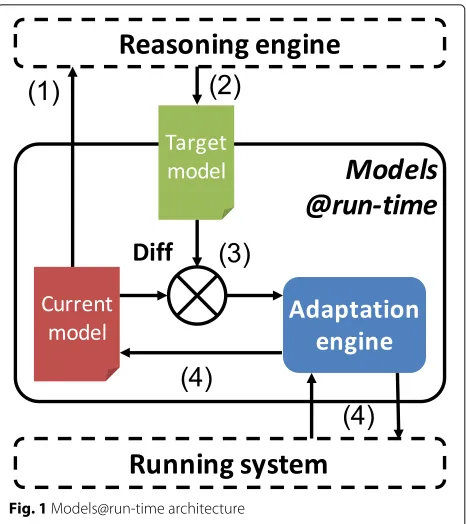
enable users to provide models that abstract away from technical details, in contrast to other CMLs. In the
mod-els@runtime approach (see Fig.1), the application state is
monitored and reflected on a certain model that abstracts from quite technical details, while any changes on this model are reflected directly on the application and its provisioning.
Third, the identification of all MCRM needed informa-tion, based on the experience of CAMEL developers in implementing other CMLs, enables automated, adaptive cross-cloud application provisioning. As CAMEL targets
1Kubernetes -https://kubernetes.io/
2Docker Swarm -https://docs.docker.com/engine/swarm/ 3Pipeline -https://github.com/banzaicloud/pipeline
Fig. 1Models@run-time architecture
DevOps, a user study was conducted in this work, in terms of adaptive provisioning of applications in the Cloud for various domains (e.g., data farming, flight scheduling). It shows the unique CAMEL benefits, i.e., a good level of usability, comprehensiveness and suitability. Fourth, to address heterogeneity and interoperability, CAMEL has
been also aligned with TOSCA. As expressed in [8]:
“Hav-ing the TOSCA standard, it is desirable to align exist“Hav-ing and potential new CMLs for providing continuous mod-eling support, for example, by achieving interoperability among the languages”.
Background
CAMEL has been developed in the framework of the
PaaSage EU project4 [38]. PaaSage’s goal is to provide
an aPaaS-like abstraction to its users enabling a vendor-neutral application specification mappable to different IaaS cloud providers. Hence, PaaSage offers an environ-ment, where application developers and operators can easily develop and deploy applications on multiple cloud infrastructures, taking advantage of flexibility, adaptivity and scalability, without having to consider the specifics of different infrastructure requirements and APIs. In that context, CAMEL is an important part of the PaaSage development and deployment platform. Its eco-system supports a dedicated social network, where the users can
share their CAMEL models [30]. Based on the above,
the aim of the current paper is to present the CAMEL language and how it addresses the issues required for
successful multi-cloud application design, whereas the actual model execution, management and adaptation is performed by other components of the PaaSage platform. Their presentation is outside the scope of the current paper. High-level information on how CAMEL is inte-grated in the PaaSage platform and its workflow are
provided in “CAMEL in the PaaSage workflow” section,
whereas dedicated papers cover specific aspects of the
platform, such as security enforcement [23].
CAMEL has already been adopted, extended and used
in several EU research projects (PaaSage, CloudSocket5,
CACTOS6) to support the modeling and execution of
applications distributed over multiple cloud environ-ments. Within these projects, CAMEL has also been
extended to support PaaS and SaaS cloud services [27]
and has been established as a baseline for the provisioning of Business Process as a Service [18]. It currently
contin-ues to evolve in the H2020 Melodic project7, to address
the challenges of multi-cloud management of large-scale
optimised data-intensive computing applications [20].
Structure of this document
The rest of the article is structured as follows. The next section presents the key step of the requirements analysis and the subsequent steps that demonstrate the ratio-nale behind how CAMEL has been defined, designed and
developed. “The CAMEL language” section provides an
overview of CAMEL, presents the key role of CAMEL in the workflow of the PaaSage platform and defines
the CAMEL metamodels. “CAMEL application: the data
farming use case” section explicates how a certain use case from PaaSage can benefit from its modelling via CAMEL and its subsequent evolution via the application of
PaaSage’s model-based MCRM framework. “Evaluation”
section introduces the user study performed in this work and discusses its main results. The related work is
reviewed in “Related work” section and a criteria-based
comparative study of the CAMEL language with other CMLs is also presented in this section. Finally, “Conclusions & future work” concludes the article and draws directions for further research.
CAMEL specification and implementation
This section presents the steps for the specification and implementation of the CAMEL. Initially the analy-sis and extraction of the CAMEL requirements is pre-sented. These form the basis for subsequent steps defined and presented as follows: (i) the definition of a suitable design and development approach, (ii) the identification of the complete set of MCRM aspects to be covered by the CAMEL language, (iii) the selection, adaptation
5CloudSocket EU H2020 Project -https://site.cloudsocket.eu/ 6CACTOS EU FP7 Project -http://cactos-cloud.eu/ 7Melodic EU H2020 Project -http://melodic.cloud
and extension of existing CMLs and DSLs to cover the MCRM aspects, (iv) defining the method for integrating these diverse languages and (v) finally the use of suit-able technologies to drive the integration method for the implementation of CAMEL.
Requirements
To create CAMEL, the following requirements were
de-rived based on the challenges presented in “Introduction”
section, summarized as: 1) support design-time and mod-els@runtime approaches, 2) unify CMLs (aspects) created in disjoint activities and prototypes and 3) achieve conver-gence with relevant standards.
– models@runtime (R1): CAMEL must support both type and instance level, enabling to specify both provider-independent and provider-specific models. The first will drive the deployment reasoning phase, thus enabling users to define non-functional and deployment requirements in a
cloud-provider-agnostic way. The second will enable to maintain a cloud-provider-specific model of both the application and monitoring topology.
– multiple aspects coverage (R2): CAMEL should enable the coverage of multiple aspects, to support all phases of the MCRM lifecycle.
– high expressiveness level (R3): A suitable
expressiveness level should be employed to capture accordingly required aspects of the respective domain. This enables both the users to specify the needed application information and the system to maintain and derive such information at a detailed level, so as to support all application lifecycle management phases.
– Separation of concerns (R4) : CAMEL should support loosely-coupled packages, each covering an aspect of MCRM. This will facilitate a faster and more focused specification of models at each phase.
– Reusability (R5) : CAMEL should support reusable types for multiple aspects of cross-cloud applications. This will ease the evolution of models.
– Suitable integration level (R6) : All CAMEL sub-DSLs should be mapped to an appropriate integration level that can support the consistency of the information provided and minimise overlap across sub-DSLs. – Textual syntax support (R7): CAMEL targets DevOps
that deal with cloud management and are akin to textual/code editing. Thus, the need to support CAMEL textual syntax arises for editing textual models.
MCRM aspects. This also enables involving different DSLs communities in CAMEL evolution, while it reduces the learning curve for DevOps already familiar with them.
Design and development
CAMEL design is inspired by component-based
approaches, which support the requirements of
sepa-ration of concerns (R4) and reusability (R5). As such,
deployment models can be regarded as assemblies of components exposing ports, and bindings between these ports. Furthermore, CAMEL developers have defined a design and development approach that satisfies the rest of the requirements and its composed by the following steps: (a)Aspect/Domain Identification[R2]; (b)Selection of Languages[R2,R3 andR8]; (c) Integration [mainly R6 but alsoR1,R4andR5]; (d)Implementation[R7].
More to the point, this approach is based on the ratio-nale of heterogeneous CMLs convergence, extension and optimization to produce one complete CML that takes benefit on the knowledge already captured in these
lan-guages [8]. Also, such an approach makes CML
main-tainability, evolution and alignment with the standards (i.e., TOSCA) more feasible, as attested also in the CMLs survey in [8]. Finally, organisations, apart from involving these experts in CAMEL development, have their own
communities, which could enable CAMEL to keep up with changes made to those individual CMLs.
Aspect Identification
Based on the knowledge and expertise of modelling experts in PaaSage, each action involved in MCRM was mapped to specific information requirements to address
a certain domain/aspect. Table 1presents the identified
aspects for fully supporting the multi-cloud application lifecycle management actions.
Language Selection
The aspects identification for MCRM, was then followed by a careful examination of existing CMLs and DSLs covering additional aspects (e.g., organisational). PaaSage experts knowledge and involvement in implementation of existing CMLs, supported greatly and assisted in selecting the following CMLs:
– Cloud Modelling Language (CloudML) [15–17] enabling to specify deployment topology models – Saloon [35–37] covering the modelling of cloud
providers and value types
– CERIF’s [21] organisation part enabling to model organisations and their access control policies – OWL-Q [25] covering the modelling of: (a)
non-functional terms (metrics and attributes), (b)
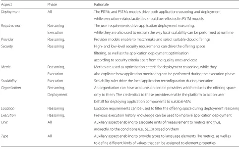
Table 1The relevant aspects for multi-cloud application management
Aspect Phase Rationale
Deployment All The PITMs and PSTMs models drive both application reasoning and deployment,
while execution-related activities should be reflected in PSTM models
Requirement Reasoning The user requirements drive application deployment reasoning,
Execution while they are also used to restrain the way local scalability can be performed at runtime
Provider Reasoning, Provider models enable to matchmake and select suitable cloud offerings
Security Reasoning High- and low-level security requirements can drive the offering space
filtering, as well as the application deployment optimisation
according to security criteria apart from the quality ones and cost
Metric Reasoning, Metrics are used as optimisation criteria for deployment reasoning, while they
Execution also explicate how application monitoring can be performed during the execution phase
Scalability Execution Scalability rules drive the local application reconfiguration during execution
Organisation Reasoning, An organisation can have accounts on certain providers which reduces the offering space
Deployment only to them. The credentials to these providers enable the platform to act on user
behalf for deploying application components to suitable VMs
Location Reasoning Location requirements can be used to filter the offering space during deployment reasoning
Execution Reasoning, Previous execution history knowledge can be used to improve application deployment
Unit All Auxiliary aspect enabling to associate units of measurement to metrics and thus,
indirectly, to the conditions (i.e., SLOs) posed on them
Type All Auxiliary aspect enabling to provide types to language elements like metrics, as well as
respective requirements or capabilities imposed on them in the form of constraints, and (c) units.
These CMLs and relevant DSLs served as the starting point covering many aspects for MCRM. Nevertheless, additional information was necessary and thus the focus was reverted on the coverage of missing aspects. In
spe-cific, the information coverage for thelocationaspect was
minimal and thus a relevant metamodel was incorporated
in CAMEL. Furthermore, for the aspects ofrequirement,
scalability, execution and security, none of the existing DSLs had sufficient information coverage. Hence, addi-tional aspect-specific DSLs were developed in CAMEL. In the end, six aspects were covered by existing partner-owned DSLs, while five were developed from scratch by considering the requirements posed on the domain by the MCRM process.
Integration
In addition to the DSLs selection, some well-known
chal-lenges in DSL integration and evolution [32] had to be
addressed, involving the following: (a) each DSL comes with its own abstract and concrete syntax, which makes it then difficult to join two or more DSLs, especially if they adopt different formalisms to define their syntax, (b) the DSLs to be integrated can have equivalent or overlap-ping concepts, which can lead to information repetition and misconceptions at the modeller side, (c) different modelling styles can be adopted leading to completely het-erogeneous DSLs resulting in lack of uniformity, and (d) different DSLs might exhibit a different description gran-ularity level, which makes it difficult to find the most appropriate detail level for integration.
To resolve these challenges, a detailed integration approach was followed that combines all DSLs to the same modelling (technical) space, description level and style by also addressing the equivalence and overlapping concepts issue. This was done by adopting the Eclipse Modeling Framework (EMF) that provides: (i) tranformation tools from various syntaxes (e.g., XML Schema) to the Ecore meta-language, (ii) semantic intra- and inter- domain val-idation of models using tools that enable the definition of
Object Constraint Language (OCL) [33] constraints, and
(iii) the production of a uniform, homogeneous concrete syntax of the CAMEL multi-DSL, using the Ecore meta-model, which follows the same modelling patterns and style. This enables modellers to rapidly specify in a similar and logical manner elements of heterogeneous DSLs. This reduces the learning curve and promotes the CAMEL usage.
The above description provides a high-level overview of the integration approach. Interested readers can find fur-ther details on the integration procedures for accomplish-ing a unified CAMEL language, as defined and explained
in [38] and also documented in the CAMEL Technical
Documentation8.
Implementation
In addition to the rich expressiveness in defining a DSL’s abstract syntax using EMF, as well as both the syntac-tic and semansyntac-tic model validation using OCL, Eclipse offers also programmatic tools enabling the DSL devel-oper to: (a) produce domain code out of an Ecore model, (b) produce a graphical editor for this DSL, (c) program-matically validate the DSL’s models and (d) produce the DSL concrete syntax. Although the Eclipse tools allow generating a graphical tree-based editor, the feedback received from the use cases partners in PaaSage while using this editor, resulted in the conclusion that DevOps (i.e., CAMEL’s main target group) are more accustomed to code-based textual editors. Hence, the Eclipse’s XText language framework was used to define the CAMEL tex-tual syntax. XText supports the automatic generation of textual editors out of the textual syntax definitions with user-friendly features, such as error highlighting, auto-completion and validation. CAMEL and its textual editor
are available in PaaSage’s repository9under the Mozilla
Public License version 2.0.
Apart from the modelling adjustments in CAMEL’s tex-tual syntax, the CAMEL model importing feature was implemented. This feature enables users to exchange and re-use CAMEL models to have a better support in their modelling tasks. For example, suppose that a user needs to specify location requirements for the VM nodes of an application topology model. If no location model is re-used, the user will need to manually develop a location hierarchy to model the desired locations of such VMs. However, by relying on a standardised location model that can be imported in a currently edited CAMEL model, the user can reduce the modelling effort by just selecting from the imported model the desired locations. In fact, this location model is already available and can be gen-erated by exploiting the model importer tool available in PaaSage’s repository. The model is constructed by
trans-forming the United Nation’s FAO geopolitical ontology10
to a model conforming to the CAMEL’s location sub-DSL. This model covers a location hierarchy involving the lev-els of continents, sub-continents and countries. Thus, it is quite sufficient to support specifying physical location requirements.
Requirements fulfillment
The design, integration and implementation steps were performed by following a process that guarantees that the
8CAMEL Technical Documentation—http://camel-dsl.org/documentation/ 9PaaSage’s Git Repository -https://gitlab.ow2.org/paasage/
eight requirements described in “Requirements” section
are satisfied. First, the CAMEL language follows the
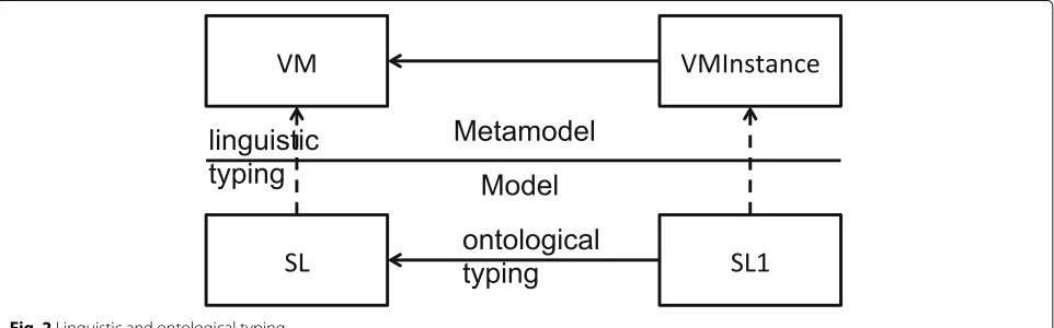
type-instance pattern [3], facilitating reusability (R3) and the
models@runtime approach (R1). This pattern exploits
two flavours of typing, namely ontological and
linguis-tic[29], as depicted in Fig.2. In this figure,SL(short for Small GNU/Linux) represents a reusable type of VM. It
is linguistically typed by the class VM (short for virtual
machine).SL1represents an instance of the virtual machine
SL. It is ontologically typed bySLand linguistically typed by
VMInstance.
Second, CAMEL follows the models@runtime
approach, mapping to the R1 requirement, as it has
been designed to utilise the abstraction of provider-independent models, which are then transformed into provider-specific ones based on matching cloud capa-bilities with the respective requirements posed. The provider-specific models can then be evolved by the system through the adaptive provisioning of the user application by still satisfying the requirements given at the provider-independent level.
The coverage of multiple aspects, i.e., requirement R2,
is one of the cornerstones of the DSL design approach. The determination of relevant aspects enabled to pro-duce an all-inclusive but focused DSL, which attempts to address the MCRM problem by covering only the most suitable information pieces. This enabled to discover suit-able DSLs that were integrated into a coherent super-DSL, i.e., the CAMEL, to reduce its development effort and time.
Requirement R3 is guaranteed at two levels: (a) by
selecting and extending (when needed) a suitable DSL to ascertain the optimal coverage of each aspect; (b) by adopting a formalism (EMF Ecore + OCL), which enables to also cover, in an expressive manner, the semantics of the respective domain.
Separation of concerns (requirementR4) is achieved by
separating the information aspects to be covered in differ-ent CAMEL packages enabling their individual evolution.
The approach to integration between DSLs enabled us to move generic or domain-specific concepts to suitable packages in the CAMEL metamodel. This allows each DSL to focus on a specific domain, thus avoiding semantic overlaps across domains.
RequirementR5 is satisfied via the design of CAMEL
and the aforementioned DSL integration process. In par-ticular, CAMEL is designed for re-usability by separat-ing between generic and aspect-specific concepts that can be re-used across different CAMEL sub-DSLs. For
instance, a Metric(part of metric DSL) is associated with
a respectiveMeasurement(part of execution DSL)
incorpo-rated in an application execution context (i.e., deployment episode). In fact, the latter is a form of cross-referencing, also enabling the inter-domain CAMEL model valida-tion. Apart from this, the CAMEL tools allow importing other CAMEL models. For example, standardised location models can be re-used for specifying location require-ments in multiple CAMEL models.
A suitable integration level (requirementR6) is achieved by using the right modelling technologies and employing the aforementioned DSL integration process. The fol-lowed procedure enabled to bring all DSLs into the same modelling space and integrate them into a unified DSL. The DSL exhibits the same modelling styles/patterns, while also caters for providing the same detail level, which is sufficient enough for capturing a specific domain by also keeping the respective modelling effort at an appropriate level.
The support for a textual syntax (requirement R7) is
provided by the CAMEL textual editor, which was imple-mented using XText and enables users to operate with CAMEL. A good effort has been spent in homogenising this syntax across different DSLs, by adopting the same modelling patterns and differentiating with respect to the default patterns automatically generated via XText. By providing user-friendly features, such as syntax highlight-ing and auto-completion, combined with the capability to import existing CAMEL models, the CAMEL editor
enhances the user experience, exhibits a suitable usability level, and enables rapid development of CAMEL models.
This has been validated in “Evaluation” section.
Finally, the re-use of DSLs (requirementR8) was one of
the design cornerstones of CAMEL. It enabled to reduce CAMEL’s development effort, to cover well the respec-tive domains in many cases, while also guaranteed the participation in this development of language engineers that have a special interest in maintaining the up-to-date versions of their DSLs within CAMEL.
The CAMEL language
In this section, an overview of CAMEL is presented first, with respect to its constituent sub-DSLs. Next, the anal-ysis will focus, also for brevity reasons, on some core sub-DSLs, i.e., those involved in the modelling of appli-cation topologies, requirements and scalability rules, thus
targeting theDevOpsusers.
In this respect, the CAMEL sub-DSLs covered in the following sub-sections include: the deployment, require-ment, metric, and scalability ones. More details on other CAMEL sub-DSLs can be found in CAMEL’s documen-tation. Also, an analysis over CAMEL’s security sub-DSL can be inspected in [24].
CAMEL overview
Based on its previously analysed design method, CAMEL was realised as a super-DSL integrating multiple
sub-DSLs/metamodels. Table 2 provides an overview of
CAMEL’s content. It explicates which are the DSLs included, supplies a list of the core domain concepts cov-ered by these DSLs, as well as the newly added concepts, and indicates the roles of users that can be responsible to provide information for these domains.
The following user roles are expected to be involved in
CAMEL model specification: (a)DevOps: represent users
responsible for defining the application non-functional and deployment requirements along with scalability rules; (b) Admin: responsible for specifying: (1) the organisa-tion model covering informaorganisa-tion about the organisaorganisa-tion running the platform and the access control policies per-taining to that platform’s usage; (2) provider models cov-ering the offcov-erings from both public and private cloud providers. Thus, there is a separation of concerns as DevOpsusers work at a higher abstraction level
(provider-independent level), whileAdminsat a lower, more cloud
provider-dependent level; (c) System: it maps to the
platform supporting the multi-cloud application deploy-ment, responsible for specifying and evolving provider-dependent models, as well as enriching the execution history of the application(s).
The separation of concerns between roles also defines when certain CAMEL model parts should be modelled or
modified. In particular,DevOpsand Adminsare usually
involved in the modelling phase as they provide informa-tion used mainly for supporting the subsequent phases. One exception concerns the provider models that can be
updated by the Admin whenever changes in the
offer-ings of respective cloud provider(s) are detected. As this change can occur at any time, this modification can span all application management phases. On the other hand, theSystemrole takes care of updating the initial CAMEL model provided by the other roles during the subsequent phases of application reasoning, deployment and execu-tion.
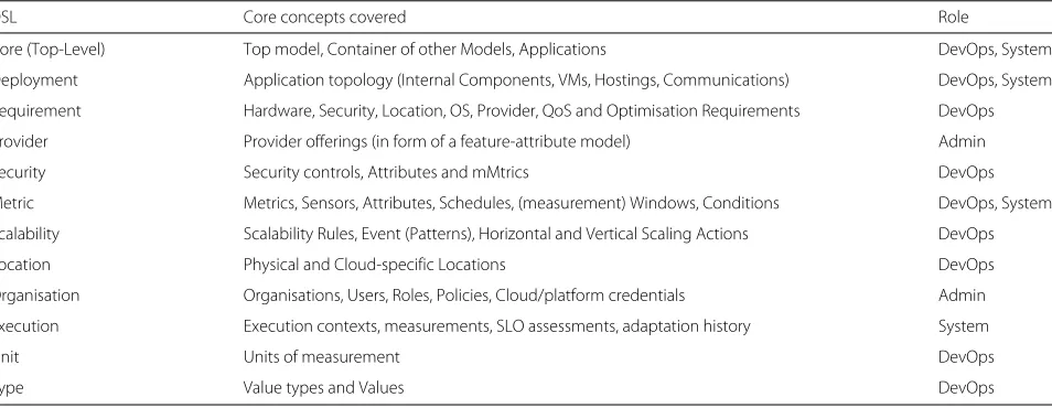
Some patterns can be derived from Table2. First, the
DevOpsrole is responsible to provide most of the domain-specific models in CAMEL. This is obvious as CAMEL targets mainly this role. However, while it can be argued that a lot of modelling effort will be contributed by this role, this is not necessarily the case. In particular, only two core models need always to be specified, i.e., the
Table 2The DSLs comprising CAMEL, the core concepts they cover and the roles responsible for providing these DSLs’ models
DSL Core concepts covered Role
Core (Top-Level) Top model, Container of other Models, Applications DevOps, System
Deployment Application topology (Internal Components, VMs, Hostings, Communications) DevOps, System
Requirement Hardware, Security, Location, OS, Provider, QoS and Optimisation Requirements DevOps
Provider Provider offerings (in form of a feature-attribute model) Admin
Security Security controls, Attributes and mMtrics DevOps
Metric Metrics, Sensors, Attributes, Schedules, (measurement) Windows, Conditions DevOps, System
Scalability Scalability Rules, Event (Patterns), Horizontal and Vertical Scaling Actions DevOps
Location Physical and Cloud-specific Locations DevOps
Organisation Organisations, Users, Roles, Policies, Cloud/platform credentials Admin
Execution Execution contexts, measurements, SLO assessments, adaptation history System
Unit Units of measurement DevOps
deployment and requirement ones. The specification of the rest of the models depends on the application require-ments. For instance, scalability rules are not needed for an application facing constant load, while security require-ments do not need to be modelled when the applica-tion does not access critical organisaapplica-tional assets. Fur-ther, template models are already offered for basic cloud providers, metrics, units and locations which could be re-used.
Second, it is evident that there are two aspects, which concern two roles, mapping to the deployment and metric DSLs. This implements CAMEL’s support for
the models@runtime approach. Hence, theDevOpsrole
provides the provider-independent topology and
met-ric models, while the Systemrole transforms them into
provider-specific models that evolve at user application provisioning.
CAMEL in the PaaSage workflow
CAMEL per se is a modelling language and framework for cloud applications and their execution status. This mod-elling itself can be generic and on a level that is indepen-dent from cloud providers, e.g., describing requirements for an application to be run; on the other hand, the mod-elling can also be specific and describe very concretely which application components shall be run on which virtual machines on what cloud provider. Being a mod-elling language, CAMEL provides the means to express these scenarios, but itself does not come with any tools
for manipulating the models or moving from provider-agnostic models to provider-specific models. Initially, such tools have been developed and evaluated in the PaaSage project and been enhanced in work since then. Even though this paper is about CAMEL as a language, this section describes PaaSage’s MCRM framework with CAMEL at its core. We hope that this illustrates the usage of CAMEL in a larger context and helps the reader to better understand.
In the following, we focus on the application deploy-ment and reconfiguration flow supported by the PaaSage framework. It is important to note that PaaSage has not been designed to be a cloud broker. Instead, its opera-tion is similar to configuraopera-tion management tools such as ansible and chef and its view is application-centric. In consequence, the storage of cloud credentials required for accessing cloud services is not overly critical, as the entire toolchain runs locally. Despite that, PaaSage uses encryp-tion to store password and credentials. The use of CAMEL in cloud-broker scenarios has been investigated by the CloudSocket project [13,18,26], but it is out of the scope of this document.
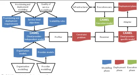
Figure3 illustrates the use of CAMEL in the PaaSage
workflow. In this figure,white trapezes represent
activi-ties performed by the user, whilewhite rectangles
repre-sent processes executed by the PaaSage framework. The coloured shapes represent modelling artifacts: the blue shapes pertain to the modelling phase, the red ones to the deployment and the green ones to the execution phase.
Modelling phase
During the modelling phase, the users develop a CAMEL application model that includes three pieces of infor-mation: (a) the provider-independent topology model (PITM) specifying the types of virtual machine (VM) nodes on which the application components should be hosted; (b) the application requirements that include Ser-vice Level Objectives (SLOs) and optimization goals over quality, cost and security terms; (c) scalability rules that drive the local adaptation behaviour of the application. Apart from the CAMEL application model, users develop (i.e., organization’s private cloud) or reuse CAMEL cloud provider models (e.g., Amazon, Azure, Organization’s pri-vate cloud), which specify the offerings supplied by these Clouds. The provider models also cover the pricing infor-mation of the Cloud provider as well as the relative performance of its offerings.
Deployment phase
The design-time CAMEL application and provider mod-els are then used by a reasoner to produce an appli-cation deployment plan solving a constraint problem. Application requirements are exploited to filter out cloud providers per application component, thus relying on component-specific requirements (e.g., # of cores - hard-ware requirements), as well as on constraints imposed
at the application level (e.g., deployment cost ≤ e 20
). The filtering dynamically generates a constraint opti-mization model that aims at the best VM offering per application component, by considering global optimiza-tion goals defined for the whole applicaoptimiza-tion (e.g., minimize
applicationcostand maximizeavailability).
This optimisation model is in the CAMEL model lead-ing to a provider-specific topology model (PSTM), cov-ering the instance level. It defines how many instances of an application component are deployed to respective VM instances, which map to a certain VM offering in the
solution. The PSTM is then exploited by theAdapterto
create a deployment plan, which defines the acquisition of resources across different Clouds, e.g. virtual machines, and the application deployment flow, i.e., deployment of application components on these virtual machines. It is the Executionware that orchestrates these actions and invokes provider-specific deployment actions and creates an execution model.
Execution phase
Once the application deployment finishes, the
execu-tion phase starts. Initially, an execution sub-model is
injected at runtime in the CAMEL model, which main-tains execution-related information about the current deployment. It includes the measurements produced by theExecutionwarefor the running application, plus SLO violations occurred that occurred at runtime. This model
not only allows to keep track of the running application, but also to exploit its execution history to improve its deployment using the Profiler and Reasoner.
The Executionware itself is realised by the
Cloudia-tor toolkit [6], a cross-cloud orchestration toolkit that
handles the acquisition of virtual resources, deployment of application artifacts, wiring of application component instances, and monitoring of both applications and vir-tual resources. Cloudiator makes use of a multitude of technologies to fulfill its functionality. Yet, for the sake of acquiring virtual resources, i.e., virtual machines, it relies on the jclouds11library where possible [5,12]. Other cloud platforms, e.g., Microsoft Azure, are supported through dedicated drivers.
Reconfiguration and adaptations
Both Executionware as well as Reasoner and Profiler may trigger actions that lead to changes: The Executionware monitors the quality of the application execution and compares live monitoring data against SLO thresholds set in the CAMEL model. Violations of these may lead to the executing local scaling rules whose execution leads to scale out/in of application components and hence to a change of the CAMEL execution model. On the other hand, Reasoner and Profiler continuously observe the application’s execution history and current state and con-tinuously produces new PSTMs, which are better than the currently applied one. If such a new configuration is found, the adapter generates a new deployment plan con-taining the difference between the current and the desired deployment that is passed on to the Executionware and enacted there. As such, a global reconfiguration loop is supported enabling to converge to an optimal application deployment, adaptable according to the current situation.
Similarly, the entire process shown in Fig.3is triggered
when the user changes the cloud provider model. This may be due to a new cloud provider being added to the model or changes in existing cloud provider models, for instance when the pricing of a provider changes, new virtual machine flavours are introduced, or the relative performance changes due to new hardware at provider side.
Both local and global reconfiguration actions are reflected in the currently applied PSTM runtime model, which enables to support the models@runtime approach, as opposed to other CMLs. In fact, the dynamic modifi-cation of the CAMEL models is performed by the system at runtime. This enables self-adaptation, i.e., the CAMEL model is "live", in contrast to other systems where such modification is manually performed at design time by the user. This is an aspect that is missing from current propri-etary cloud application management systems and CMLs, that manage even single Clouds.
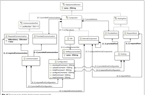
Fig. 4The type part of the deployment metamodel
CAMEL metamodel
The CAMEL core metamodel is technically represented as an Ecore model and organised into eleven metamod-els/packages. Each metamodel/package reflects a certain domain. The core package includes generic concepts,
re-used across different domains, as well as the CamelModel
acting as a top-level container. For brevity and to limit the technical details, only the deployment, requirement, met-ric and scalability metamodels are introduced fully. The rest of the metamodels are briefly introduced. Readers can refer to the CAMEL Technical Documentation and
CAMEL Semantics12 for more details on the individual
metamodels.
Deployment Metamodel
The deployment metamodel follows the type-instance pattern where the type part specifies a PITM while the
instance part a PSTM. Figure4depicts the type part. The
instance part is not shown as it is identical to the type part with the exception that instances (e.g.,VMInstance) of
type-based concepts (e.g.,VM) are modelled, always pointing to
their type.
12CAMEL Semantics -http://camel-dsl.org/documentation/
The top-level entity in the deployment metamodel is DeploymentModel, i.e., a container of provider-independent deployment elements. At the type level, the basic but
abstract entity isComponent. Following a component-based
modelling approach, this entity has a set of provided communication and required communication ports. The former enable it to communicate with other components, while the latter to host other components. It includes also
a set ofConfiguration elements, in the form of OS-specific
commands, for lifecycle management, i.e., to download, install, configure, run and stop this component.
AComponententity subsumes two component types: (1) theInternalComponentrepresents a software component to be deployed in the Cloud, requiring to be hosted by another Component(eitherInternalComponentorVM) via aHostingPort(for instance, a servlet container can host a servlet, where both areInternalComponents) and (2) theVMwhich acts as a host for internal components.
ACommunicationis established by connecting the provided and required communication ports of two components. This communication’s lifecycle can also be managed via twoConfiguration elements. The first focuses on managing the provided, while the second the required
draws the following values from theCommunicationType
enu-meration: (a)LOCAL: denoting that the internal components
connected need to be hosted on the sameVM node; (b)
REMOTE: signifying that the two components should be
hosted on different VM nodes; (c) ANY: denotes that the
management platform is allowed to decide about the related placement of these two components, i.e., whether to co-locate them or not.
The second connector type maps to theHostingconcept,
representing a hosting relation between two components: the hosted internal component and a hosting internal
component or VM. Similarly to a Communication, a Hosting
connects the provided and required hosting ports of the
two components, while it includes two Configuration
ele-ments, each devoted to the management of one of the two hosting ports.
TheVMRequirementSetincludes a set of references to spe-cific kinds of requirements that can be modelled in a requirementmodel, such as quantitative hardware, location
or OS requirements (see Listing2). AVMRequirementSetcan
be associated to aVM or to the whole DeploymentModel. In
the latter case, it represents global VM requirements that must hold for the whole application topology. In the for-mer case, it represents local VM requirements that must hold for a certain VM only, which take priority over global requirements.
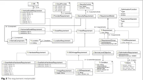
Requirement metamodel
CAMEL’s requirement metamodel, depicted in Fig.5, can
capture the user non-functional requirements, including
hardware, quality, cost, location and security ones. It has
been inspired by the WS-Agreement [1] and OWL-Q [25]
languages. This metamodel includes the top-level
Require-mentModelconcept, which can contain zero or more
Require-ments. AnyRequirementcan be either hard (seeHardRequirement concept) or soft (seeSoftRequirementconcept). Hard require-ments should be satisfied at all costs by the respective platform, while soft requirements should be satisfied on a best-fit basis.
Requirements can be grouped by using the
Requirement-Groupsub-concept ofRequirement. A certain logical operator (AND, OR or XOR) is applied over the requirements grouped to formulate goal models, inspired by goal
mod-elling approaches like i-star [41]. The requirement
group-ing enables to specify alternative service levels (SLs), defined as requirement conjunctions. This caters for a more flexible filtering of the provider space, increasing the possibility that a solution to the deployment reasoning problem can be reached.
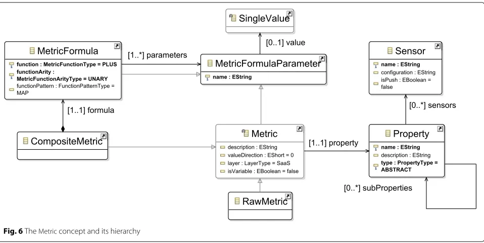
Metric metamodel
CAMEL’s scalability and metric packages rely on the SRL
DSL [14, 22], enabling to specify rules supporting
com-plex adaptation scenarios of cross-cloud applications. The metric package captures the way application monitoring can be performed and the main monitoring conditions
to be evaluated. The former is specified via the Metric
abstraction, while the latter by theConditionconcept.
The metric metamodel (see Fig. 6) follows the
type-instance pattern, an essential feature that distinguishes it
Fig. 6TheMetricconcept and its hierarchy
from the state-of-the-art. This feature enables the respec-tive (multi-cloud) application management framework to maintain and evolve the application monitoring infras-tructure by following the models@runtime approach. This infrastructure should be synchronised with the changes performed on the application’s PSTM model.
Scalability metamodel
SRL, apart from measurement constructs, also enables the modelling of scalability rules by including a
scala-bility metamodel (Fig. 7). SRL is inspired by the Esper
Processing Language (EPL)13with respect to the
specifi-cation of event patterns with formulas including logic and timing operators. SRL offers mechanisms to (a) specify event patterns and associate them with monitoring data, (b) specify scaling actions, and (c) associate these scal-ing actions with event patterns. In the followscal-ing, the main concepts defined in thescalabilitypackage are presented and analysed.
ScalabilityModelacts as a container for other scalability con-cepts, from which the most central isScalabilityRule. This rule is mainly a mapping from an event to one or more scaling actions. It also specifies additional details, such as which
is its developer (anEntity) and which scaling requirements
(seeScaleRequirementin Section8) should limit its triggering. AnyScalingActionis associated with a certainVMand it can be either horizontal or vertical.
Other metamodels
Provider Metamodel:Theproviderpackage of the CAMEL
metamodel is based on Saloon [35–37]. Saloon is a
13https://www.espertech.com/esper/
tool-supported DSL for specifying the features of cloud providers and matching them with requirements by lever-aging feature models [7] and ontologies [19]. It provides the capability to define the attributes and sub-features characterising a private or public cloud provider, e.g., the attributes characterising the virtual machine flavours pro-vided by a private or public cloud. It also covers the costs and relative performance of individual offerings of a provider. The provider models enable matchmaking and selecting suitable cloud provider offerings, while they also unveil details specific to the application deployment.
Execution Metamodel: The execution metamodel in CAMEL has been developed from scratch with the main goal to cover the modelling of whole execution histo-ries of multi-cloud applications. Such information can then be exploited by the management platform in order to optimise the deployment of a multi-cloud application, whether it is a new or an existing one. In this respect, an execution model is a container of different deployment episodes and enables the analysis on them to derive the added-value deployment-reasoning-targeting knowledge. Such a model not only allows to keep track of the run-ning application but also to exploit its execution history to improve its deployment.
Fig. 7Thescalabilitymetamodel
Location Metamodel: The location metamodel captures the modelling of hierarchical physical and cloud-based locations. This modelling enables specifying location requirements that can drive the filtering of the VM offer-ing space in deployment reasonoffer-ing, while also ensur-ing the compliance to regional or continental regulatory
requirements. For example, as part of theLocationan
iden-tifier is defined (e.g., ISO code for physical locations) and
can be further distinguished into aGeographicalRegionand a
CloudLocation.
Organisation Metamodel:Theorganisationpackage of the CAMEL metamodel is based on the organisation subset of
CERIF [21]. CERIF is an EU standard for research
infor-mation. In particular, the organisation package of CAMEL
reuses the concepts from CERIF for specifying organisa-tions, users, and roles. As a central part of theorganisation model, the specific organisation details are defined, such as itsname, contactemailaddress, web URL.
Type Metamodel:The typemetamodel is also based on Saloon [35–37]. It provides the concepts to specify value types and values used across the rest of the CAMEL models (e.g., integer, string, or enumeration).
CAMEL application: the data farming use case The Scalarm platform’s14[28] data farming use case allows illustrating how to specify CAMEL models conforming to CAMEL’s textual syntax. We limit the presentation
to those specific CAMEL sub-models presented in “The
CAMEL language” section to illustrate the definition of essential properties for the use case. Readers interested in the complete concrete syntax of CAMEL should refer
to [39]. The complete Scalarm CAMEL model can be
downloaded from PaaSage’s Git repository at OW215.
Scalarm overview
Scalarm is a complete platform for conducting data farming experiments across heterogeneous computing infrastructures. It has been developed by the Akademia Grniczo-Hutnicza (AGH) University of Science and Tech-nology. Data farming represents a methodology via which a simulation model is repeatedly executed according to an extensive parameter space such that sufficient data can be
14Scalarm -http://www.scalarm.com/
collected with the goal to provide an insight over the cor-relation between the model properties and behaviour, as well as the simulation’s input parameters. Thus, Scalarm supplies to the user a set of well-known experiment design methods to generate the experiment parameter space.
Via Scalarm, each data farming experiment can be monitored, while the initial parameter space can be extended at runtime. Further, the amount of computa-tional resources dedicated to the experiment execution can be increased such that Scalarm can scale itself based on the experiment size.
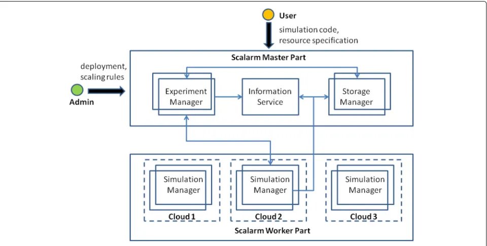
Scalarm architecture
The Scalarm architecture follows the master-worker
design pattern and is depicted in Fig.8. In this
architec-ture, the worker part executes the simulation, while the master part coordinates the execution of the data farming experiments. Each part from the two is realized by using loosely coupled services.
In terms of the worker, the main component is the
Sim-ulation Manager, an intelligent wrapper for simSim-ulations capable to be deployed on different infrastructures. It
implements the Pilot job concept [10] by being a
special-ized application that acquires computations resources to run actual simulations.
In terms of the master, (3) components are
rele-vant: the Experiment Manager, Information Serviceand
Storage Manager. The Experiment Manager supplies an overview about both running and completed data farm-ing experiments, while it enables analysts to create new
experiments or conduct statistical analysis on existing experiments. It is also responsible for scheduling
sim-ulations to Simulation Managers. TheStorage Manager
constitutes a persistence layer in the form of a ser-vice enabling other components or serser-vices to store different types of information, which include struc-tural information about executed simulations and exper-iments, as well as actual simulation results, either in
the form of binary or text data. Finally, the
Informa-tion Service realizes the service locator pattern, con-stituting a registry of other services and components in the Scalarm system enabling the retrieval of their location.
Due to the master-worker architecture there is no immediate communication between the workers. Due to the fact that workers pull their upcoming experiments from the master, but the compute time per experiment is significantly longer than this communication (order of hours compared to orders of seconds), the application is particularly well suited for multi-cloud deployments, as there is no dependency on bandwidth and latency.
As-is and to-Be situation
Before employing the PaaSage platform, the user needs to manage the worker’s resources by manually schedul-ing extra workers to different infrastructures. More-over, the administrator needs to manually define scaling rules to specify scaling conditions and actions for each internal service for the master. On another note, the multi-cloud aspect and the complex scaling requirements
of Scalarm disallow the use of widely used container orchestrators, such as Kubernetes and Docker Swarm, since they only support the definition of basic scal-ability rules and do not support multi-cloud
deploy-ment. As mentioned in Section 8, a Kubernetes cluster
needs to be deployed manually in each cloud provider or Pipeline can be used to deploy Kubernetes clusters on major cloud providers through a unified interface before an actual application and its workload can be deployed.
By using the PaaSage platform and CAMEL, Scalarm became a fully autonomous data farming platform. This was achieved by using suitable scalability rules that enabled the automatic scaling of Scalarm components when certain conditions are met. These rules are derived
by the Reasoner component in the PaaSage platform
by considering the user’s non-functional requirements. Furthermore, Scalarm initial deployment is handled by PaaSage itself so that there is no need to involve a system administrator or a user to perform scaling/de-ployment actions, as the PaaSage platform automatically handles all Scalarm services. Moreover, via PaaSage and CAMEL, Scalarm managed to be executed in multi-cloud environments. Multi-Cloud deployments free Scalarm from vendor lock-in and allows for fine-grained opti-mization of computation cost by selecting the cheap-est possible cloud providers for executing large scale data experiments. The master-worker architecture of Scalarm makes it mostly insusceptible to network latency problems (which may result from highly geographically distributed deployments), and data farming does usu-ally only requires to distribute the simulation binary - the input and output data remain reasonably small to avoid high of data transfers. Finally, by exploiting the Scalarm CAMEL model, which is publicly avail-able, and modifying it according to specific deploy-ments, PaaSage users can conduct data farming experi-ments without any prior investment in software infras-tructure or the development of the right coordination software.
The scalarm cAMEL model
The key requirements for the Scalarm use case are the ability to define and modify the deployment model, as well as to specify both appropriate requirements and rules for autonomously conducting different data farming experi-ments. For these reasons and the need to showcase the Scalarm model definition in a clear and neat way, we present the deployment, requirement, metric and scala-bility models. All other models are accessible through the PaaSage repository16.
16Scalarm Model -https://gitlab.ow2.org/paasage/camel/blob/master/ examples/
The scalarm deployment model.
The main concepts in thedeploymentDSL are now
exem-plified via the Scalarm use case. As such, part of the
deployment model is defined in Listing 1to reduce the
model length and complexity. The “...” denotes additional CAMEL elements omitted from readability.
Listing 1Scalarm Deployment model (excerpt)
1 deployment model ScalarmDeployment { 2 requirement set
CoreIntensiveUbuntuGermanyRS {
3 os: ScalarmRequirement.Ubuntu 4 quantitative hardware:
ScalarmRequirement.CoreIntensive
5 location: ScalarmRequirement.
GermanyReq
6 }
7 vm CoreIntensiveUbuntuGermany { 8 requirement set
CoreIntensiveUbuntuGermanyRS
9 provided host
CoreIntensiveUbuntuGermanyHost
10 }
11 requirement set
CPUIntensiveUbuntuGermanyRS {
12 os: ScalarmRequirement.Ubuntu 13 quantitative hardware:
ScalarmRequirement.CPUIntensive
14 location: ScalarmRequirement.
GermanyReq
15 }
16 vm CPUIntensiveUbuntuGermany { 17 requirement set
CPUIntensiveUbuntuGermanyRS
18 provided host
CPUIntensiveUbuntuGermanyHost
19 } 20 ...
21 internal component ExperimentManager { 22 provided communication ExpManPort {
port: 443}
23 required communication StoManPortReq
{port: 20001 mandatory}
24 required communication InfSerPortReq
{port: 11300}
25 required host
CoreIntensiveUbuntuGermanyHostReq
26 ...
27 }
28 internal component SimulationManager { 29 required communication InfSerPortReq
{port: 11300}
30 required communication StoManPortReq
{port: 20001}
31 required communication ExpManPortReq
{port: 443}
32 required host
CPUIntensiveUbuntuGermanyHostReq
33 ....
34 } 35 ...
36 communication
SimulationManagerToExperimentManager {
37 from SimulationManager.ExpManPortReq
to ExperimentManager.ExpManPort
40 hosting
ExperimentManagerToCoreIntensiveUbuntu Germany {
41 from ExperimentManager.
CoreIntensiveUbuntuGermanyHostReq to
42 CoreIntensiveUbuntuGermany.
CoreIntensiveUbuntuGermanyHost
43 } 44 hosting
SimulationManagerToCPUIntensiveUbuntu Germany {
45 from SimulationManager.
CPUIntensiveUbuntuGermanyHostReq to
46 CPUIntensiveUbuntuGermany.
CPUIntensiveUbuntuGermanyHost
47 } 48 ...
As dictated by its architecture (see Fig. 8), Scalarm
comprises four internal components, from which two are presented here along with their respective deployment
requirements. The ExperimentManager has one provided
communication port (443) and two required communica-tion ports (20001 & 11300). It also requires to be hosted on
a core intensive VM (i.e., hosting port).SimulationManager
has three required communication ports (11300 & 20001 & 443) and requires to be hosted on a CPU intensive VM (i.e., hosting port). The two internal components define required hosting ports that need different VM nodes. In particular, VM nodes must be associated with a 64bit Ubuntu OS and be located in Germany, i.e., the nearest place to Poland where major cloud providers have data
centres (see requirement model in Listing2).
The scalarm requirement model.
In the above deployment model definition, the quanti-tative hardware requirements that must be respected by the corresponding VMs are referenced. The core intensive
VM, defined in the model asCoreIntensiveUbuntuGermany,
is associated with a quantitative requirement to incorpo-rate 8 to 32 cores and have a memory size from 4096 to 8192 MB, while the CPU intensive VM, named as CPUIntensiveUbuntuGermany, must support a memory size between 8192 and 16384 MB. These requirements are actually specified (along with others) in the requirement
model presented in Listing2.
Listing 2Scalarm Requirement model (excerpt)
1 requirement model ScalarmRequirement { 2 quantitative hardware CoreIntensive { 3 core: 8..32
4 ram: 4096..8192
5 }
6
7 quantitative hardware CPUIntensive {
8 core: 1..
9 ram: 4096..8192 10 cpu: 1.0..
11 }
12 ...
13 os Ubuntu {os: ’Ubuntu’ 64os} 14
15 location requirement GermanyReq { 16 locations [ScalarmLocation.DE]
17 }
18 ...
19 horizontal scale requirement
HorizontalScaleSimulationManager {
20 component: ScalarmModel.
ScalarmDeployment.SimulationManager
21 instances: 1 .. 5
22 }
23 ...
24 slo CPUMetricSLO {
25 service level: ScalarmModel.
ScalarmMetric.CPUMetricCondition
26 }
27 ...
The scalarm scalability model.
Listing3showcases the sole scalability rule of the Scalarm
application, which attempts to increase the number of
instances of the SimulationManager component by one
when the mean CPU utilisation in its correspondingVMis
equal or goes above 80%.
Listing 3Scalarm Scalability model (excerpt)
1 scalability model ScalarmScalability { 2 horizontal scaling action
HorizScaleSimulationManager {
3 type: SCALE OUT
4 vm: ScalarmModel.ScalarmDeployment.
CPUIntensiveUbuntuGermany
5 internal component: ScalarmModel.
ScalarmDeployment.SimulationManager
6 }
7
8 non-functional event CPUAvgMetricNFEAny
{
9 metric condition: ScalarmModel.
ScalarmMetric.CPUAvgMetricConditionAny
10 violation
11 }
12 ...
13 scalability rule CPUScalabilityRule { 14 event: ScalarmModel.
ScalarmScalability.CPUAvgMetricNFEAny
15 actions [ScalarmModel.
ScalarmScalability.
HorizScaleSimulationManager]
16 scale requirements [
ScalarmRequirement.
HorizontalScaleSimulationManager]
17 }
18 }
This scalability rule, named as CPUScalabilityRule,
maps the CPU specific event CPUAvgMetricNFEAnyto the
HorizontalScalingSimulationManager scaling action. It is
also associated to the HorizontalScaleSimulationManager
scale requirement (see Listing 2) denoting that the
number of instances of SimulationManager should
be at most 5, thus representing the actual upper scalability limit to hold for the scalability rule. The
HorizontalScalingSimulationManager action indicates
out, as hosted by the CPUIntensiveUbuntuGermany VM node, with an additional instance. On the other hand,
the CPUAvgMetricNFEAny is a single non-functional
event directly mapping to the violation of the
CPUMetricConditioncondition, as indicated in Listing4.
The scalarm metric model
For brevity, the analysis focuses only on how the
CPUAverage composite metric and its condition can be
specified in CAMEL (see Listing4. This metric condition
participates in theCPUMetricSLOas indicated in Listing2and
theCPUAvgMetricNFEAnynon-functional event in Listing3.
Listing 4Scalarm Metric model (excerpt) 1
2 metric model ScalarmMetric {
3 ...
4 property CPUProperty { 5 type: MEASURABLE
6 sensors [ScalarmMetric.CPUSensor]
7 }
8 ...
9 sensor CPUSensor {
10 configuration: ’de.uniulm.omi.
cloudiator.visor.sensors. SystemCpuUsageSensor’
11 push
12 }
13 ...
14 raw metric CPUMetric { 15 value direction: 0 16 layer: IaaS
17 property: ScalarmModel.
ScalarmMetric.CPUProperty
18 unit: ScalarmModel.ScalarmUnit.
CPUUnit
19 value type: ScalarmModel.
ScalarmType.Range_0_100
20 }
21 ...
22 composite metric CPUAverage {
23 description: "Average of the CPU" 24 value direction: 1
25 layer: PaaS
26 property: ScalarmModel.
ScalarmMetric.CPUProperty
27 unit: ScalarmModel.ScalarmUnit.
CPUUnit
28
29 metric formula Formula_Average { 30 function arity: UNARY
31 function pattern: REDUCE 32 MEAN( ScalarmModel.
ScalarmMetric.CPUMetric )
33 }
34 }
35 ...
36 raw metric context CPURawMetricContext
{
37 metric: ScalarmModel.ScalarmMetric.
CPUMetric
38 sensor: ScalarmMetric.CPUSensor 39 component: ScalarmModel.
ScalarmDeployment.SimulationManager
40 schedule: ScalarmModel.
ScalarmMetric.Schedule1Sec
41 quantifier: ANY
42 }
43 ...
44 composite metric context
CPUAvgMetricContextAny {
45 metric: ScalarmModel.ScalarmMetric.
CPUAverage
46 component: ScalarmModel.
ScalarmDeployment.SimulationManager
47 window: ScalarmModel.ScalarmMetric.
Win1Min
48 schedule: ScalarmModel.
ScalarmMetric.Schedule1Min
49 composing metric contexts [
ScalarmModel.ScalarmMetric. CPURawMetricContext]
50 quantifier: ANY
51 }
52 ...
53 metric condition CPUMetricCondition { 54 context: ScalarmModel.ScalarmMetric
.CPUAvgMetricContextAny
55 threshold: 80.0
56 comparison operator: >
57 }
58 ...
59 schedule Schedule1Min { 60 type: FIXED_RATE 61 interval: 1
62 unit: ScalarmModel.ScalarmUnit.
minutes
63 }
64 schedule Schedule1Sec { 65 type: FIXED_RATE 66 interval: 1
67 unit: ScalarmModel.ScalarmUnit.
seconds
68 }
69 window Win1Min {
70 window type: SLIDING 71 size type: TIME_ONLY 72 time size: 1
73 unit: ScalarmModel.ScalarmUnit.
minutes
74 }
75 ...
The CPUAveragecomposite metric is calculated by the
Formula_Averageformula, which applies theMEANfunction
over theCPUMetric, a raw metric computed by the
push-basedCPUSensorsensor, part of the PaaSage platform and
especially theExecutionwaremodule.
CPUMetricCondition is a composite metric
condi-tion imposing that the metric refer to as CPUAverage
should be less than 80%. This condition refers to the
CPUAvgMetricContextAny composite metric context. This
context explicates the CPUAveragemetric’s schedule and
window, as well as that it is applied over the
Simulation-Managercomponent. It also refers to the composing
met-ric’s raw metric context named as CPURawMetricContext.
TheCPUAverage’sSchedule1Minschedule specifies that the
metric’s measurements will be computed repeatedly every
1 min, according to the metric’sWin1Minsliding window.
CPURawMetricContextis the raw metric context for the
CPUMetric. It explicates that the CPUSensor will be used
Schedule1Secschedule, which means thatCPUMetric’s mea-surements will be calculated every 1 s.
Evaluation Population
For evaluation purposes, CAMEL was exposed to differ-ent practitioners in the context of the PaaSage project use cases. Practitioners were recruited from the personnel of the organisations participating in the project that were responsible for specific use cases. 23 individuals partici-pated in the study. In order to drive analysis of the results, using the two way ANOVA test, the participants were separated to four groups based on their MDE and cloud knowledge. MDE and cloud knowledge were selected as the two independent variables due to the need for eval-uation of CAMEL against the dependent variable: i.e., usefulness or ease of use. In fact, the groups are: (i) 35% of the participants are under Group 1 with less to
aver-age knowledge of MDE and cloud (MDE≤3,Cloud≤3),
(ii) 22% of the participants are under Group 2 with less to average knowledge of MDE and excellent knowledge of
Cloud (MDE≤3,Cloud>3), (iii) 13% of the participants
are under Group 3 with excellent knowledge of MDE and
less to average knowledge of Cloud (MDE>3,Cloud≤3)
and (iv) 30% of the participants are under Group 4 with excellent knowledge of MDE and with excellent knowl-edge of Cloud (MDE>3,Cloud>3). Hence, the research questions were defined by taking into consideration the competences of the groups. Finally, all participants com-pleted the evaluation questionnaire, which indicates that all results are valid for analysis.
Methodology
The main aim of the evaluation was to collect practi-tioners’ feedback regarding the use and capabilities of CAMEL, and this feedback was considered in the first evaluation steps for updating CAMEL and its modelling environment, in order to make sure that the language covers well different needs. The research study evalua-tion methodology is based on two factors. In specific, the evaluation results were extracted on the basis of the
Technology Acceptance Model (TAM) [4,11], where the
following TAM factors were considered:
– Perceived Ease of Use (PEU) : the degree to which a user believes that CAMEL reduces the effort in modelling tasks.
– Perceived Usefulness (PU) : the degree to which a user believes that using CAMEL enhances the modelling tasks’ performance.
The participants used CAMEL language and edi-tor in the context of different business and research domains, i.e., Data Farming, Automotive Simulation,
Flight scheduling, ERP, Financial Services and Human Milk Bank, and completed a questionnaire for evaluat-ing the above TAM factors. The studied use cases are
summarised in Table3. For more information on the use
cases the interested reader may refer to the PaaSage
web-site17. In specific, the following steps were used for the
evaluation:
– The participants were familiarised with different CAMEL versions, reported bugs, requested features, and supplied feedback to developers.
– The participants modelled their use cases scenarios with the final version of CAMEL language and editor. – The participants assessed CAMEL features via an
online questionnaire18.
Based on the above, the final questionnaire was divided into different section, covering : usability of the CAMEL Textual Editor, CAMEL documentation, CAMEL Requirements, CAMEL Metric Model, CAMEL Deploy-ment Model, CAMEL Scalability Rules and CAMEL Organisation Model, whereas demographic data and prior user knowledge were also collected. The most important
results are assessed in “Technology acceptance” section
to examine the opinion of the participants as to the use-fulness and the ease of use of the CAMEL language and editor, which indicates their willingness to accept and use the new technology. The evaluation of the whole PaaSage platform, e.g., in terms of performance, is not covered in this work.
Moreover, a statistical analysis is applied on the eval-uation results for reliability purposes and for detecting useful conclusions (e.g., does the MDE experience of the participants affects their opinion in terms of PU and PEU for CAMEL). Initially, the Cronback’s Alpha coefficient was used for testing the reliability of the scale items. Following, a two factor ANOVA with replication was per-formed to examine the effect of the two independent variables (MDE and Cloud experience) on a dependent variable – PU or PEU (i.e., the test was executed twice). This test also examines whether the interaction of the two independent variables affect each other to influence either the PU or PEU dependent variable. Finally, a paired sam-ple t-test was performed to determine whether the mean difference between two sets of observations (i.e., PU and PEU) is significant for the same population.
Reliability analysis
Cronbach’s alpha was used in this work as a measure of internal consistency (i.e., reliability) for the designed instrument. This coefficient is used since it provides the capability to determine if a scale that is composed of multiple Likert questions in a survey is reliable. In specific,
17PaaSage use cases -https://paasage.ercim.eu/use-cases/