A System for Multimodal Interaction with
Kinect-Enabled Virtual Windows
Ana M. Bernardos, Íñigo Marquínez, David Gómez, Juan A. Besada, José R. Casar
Universidad Politécnica de Madrid, ETSI TelecomunicaciónMadrid, Spain
{abernardos, imarquinez, david.gomez, besada, jramon}@grpss.ssr.upm.es
Abstract—Commercial off-the-shelf gaming devices (e.g. such as Kinect) are demonstrating to have a great potential beyond their initial service purpose. In particular, when integrated within the environment or as part of smart objects, peripheral COTS for gaming may facilitate the definition of novel interaction methods, particularly applicable to smart spaces service concepts. In this direction, this paper describes a system prototype that makes possible to deliver multimodal interaction with the media contents in a Virtual Window. Using a Kinect device, the Interactive Window itself adjusts the video clipping to the real time perspective of the user – who can freely move within the sensor coverage are. On the clipped video, the user is able to select objects by pointing at meaningful image sections and to initiate actions related to them. Voice orders may also complete the interaction when necessary. Although implemented for smart spaces, the service concept can also be applied to learning, remote control processes or teleconference.
Keywords-multimodal interaction; virtual windows; deictic interaction; smart spaces; smart objects.
I. INTRODUCTION
Systems equipped with multimodal interaction offer the possibility of interfacing with them through a combination of natural modes of communication, which may include speech, body gestures, handwriting, graphics or gaze. This mixing should be closer to the effective human-to-human communication, but the creation of satisfactory models that handle the inputs in an integrated way is still an open challenge [1]. Nowadays, thanks to commercial off-the-shelf technologies, in particular to gaming peripheral devices such as Microsoft Kinect (first version launched in November 2010), it is possible to implement new concepts of interaction that may enhance our relationship with daily-life spaces. For example, in our previous works, we have prototyped a Kinect-enabled Virtual Window [2]; the Window is responsive to the viewer’s perspective (which is inferred from her/his head, body pose and movements) and delivers a realistic window feeling by clipping a video stream. Users have satisfactorily evaluated the perception obtained when different layers of processing are added to Kinect’s raw measurements.
We have also explored deictic interaction in smart spaces. The pointing gesture is universally used as a way to denote or attract interest towards an item. In [3], it is described how to make a space sensitive to 3D pointing directives to command the space’s objects. The system combines the input from two
Kinect devices to track the user and retrieve her joints spots for positional analysis. To demonstrate its applicability, the system has been prepared to control rows of ceiling lamps; user tests show that 90% of interactions are successful when the user is inside the optimal Kinects’ coverage area.
On the technology developed for these two systems, we have built and prototyped a concept to provide enhanced interactivity to the Virtual Window. Apart from the pose, we aim at making this Interactive Virtual Window responsive to pointing gestures to indicate the viewer’s interest towards a part/object in the scene (selection process), at the same time that speech control is used to activate specific actions related to the pointed item (action process) if needed. The idea of combining pointing and speech for interaction is not new; the proposed system aims at exploring it as new services enabler for smart spaces. The paper contextualizes this research and provides a description of the system architecture and its components.
II. STATE OF THE ART
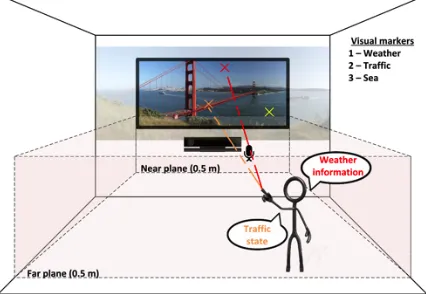
Kinect device integrates a low-cost depth sensor, an RGB camera and a multi-array microphone to facilitate full-body 3D motion capture and facial and voice recognition. Kinect 2.0, released in 2014, tracks up to 25 joints per person and six complete skeletons simultaneously. Among its improvements against version 1.0, it delivers higher depth fidelity, provides major stability for body tracking and works in a wider field of view, being its effective distance coverage area from 40 cm to 4.5 meters (Figure 1).
The device is being increasingly used as a tool for interaction research. It is inexpensive, portable and has a great potential to gather features, poses and gestures of moving people in its area of sight. In particular, a review of the device performance for pointing tasks, which are used in this work, can be found at [4]. In [5], Kinect facilitates interacting with objects in a virtual 3D space by pointing. The pointing vector is obtained from paired elbow-hand joints positions, and object selection is derived from the movements of a hand-mounted 3D mouse. Authors find that variations over the posture (sitting vs. standing) may influence the pointing detection accuracy due to fatigue. The same corporal reference points are used for creating the pointing vector in [6]. In this occasion, the system enables the selection and management of a smart TV. In [7], the human pointing gestures are interpreted to catch the attention of a robot: the robot goes toward a target location that is indicated by the user. This position is also estimated through a Kinect sensor.
INTETAIN 2015, June 10-12, Torino, Italy Copyright © 2015 ICST
Different Kinect-detectable gestures are configured in [8] to interact with 3D medical images. Pointing is one of the recognized ones; in this case the pointing vector is obtained as a combination of the users’ eye location and the position of the index finger’s tip. The problem of hand self-occlusion (when the user’s body position hinders the identification of the hand reference points) is considered at [9]; the work explains a method for compensation when the shoulder is detected but the hand occluded. In [10], Kinect depth camera is used to detect the coordinates of a subject's right hand to enable the user to perform posterior manipulation of the position of a cursor. NUICursorTools [11] is a toolkit that provides cursor transformation functions for diverse input modalities. It aims at offering a device agnostic solution to eliminate inherent limitations of human motor control in mid-air, in particular undesirable jitter from continuous hand tremor. Through this tool, it is possible to create a pointer on a wall-sized display that can be controlled via a markerless motion tracking sensor, such as a Kinect device.
Hand pointing is compared to gaze pointing for 3D virtual environments in [10] – gaze tracking is also available through Kinect’s API. Authors reach the conclusion that each pointing technique has different performance in terms of accuracy and fatigue, thus these facts should be taken into account when including pointing at interaction method. Regarding combined speech-pointing interaction, research dates back to the 80s, with the Put That There demonstration system. For example, [12] shows that speech-pointing interaction is preferred by the users for target selection when compared to dwell time and shake hand movement.
Obviously, Kinect has been widely used to detect corporal gestures in video games [13], although the pointing action is not widely exploited. An example is [14], a system that tracks the user’s pose and gaze direction to control the famous “Candy Crush” game: corporal gesture is used for interaction, while targets are selected using gaze pointing. The movements of the arm indicate actions inside the game, but do not drive any pointing gesture. This is similar to [15], a single-player game that uses the angle of the player’s torso in relation to the ground to help a virtual avatar keep balance in a wobbling world.
A comparative analysis of modern gaming input devices is available at [16]: users were asked to perform a shooting task and performance measurements with four devices. Results show that the mouse is still the best tool, while the game controller remains in a close second position. The performance of the 3D input devices (Move and Kinect) was significantly worse. How older adults react to motion-based games is researched at [17]. A comparative test youngsters vs. elderly was designed to measure the user’s performance while accomplishing three different tasks: pointing (the speed at which a person can move a pointer to a target), steering (the speed at which a person can move a pointer along a path without colliding with the path’s borders) and pursuit tracking (the ability to move a pointer so as to accurately match the location of a moving target). Tasks were carried out by using Kinect, Move, Mouse and GamePad. Conclusion shows that elderly are capable to efficiently use and enjoy motion-based game controls.
On this review of Kinect-enabled pointing methods and its uses within interaction, next Section presents an interaction system that exploits multimodality in an Interactive Virtual Window.
III. SYSTEM DESCRIPTION
The proposed system integrates the Virtual Window concept described in [2], which translates a moving observer point of view into video clipping to simulate the resulting perspective, with two additional interaction components: a) a pointing detector, that estimates the coordinates in the image the user is pointing at; and b) a window-related grammar speech recognizer, in order to make possible for a user to show interest against meaningful items in the scene and trigger actions/services related to them. This Section describes the general system architecture.
A. Service approach
The Virtual Window concept aims at providing a decorative element that offers a realistic window effect to be integrated within working spaces, hospitals, hotels, etc., in general within spaces with limitations regarding their orientation or views. In practice, the Virtual Window system components include a display (or a set of displays), a Kinect sensor and the necessary computation resources to manage and adapt videos to the user pose. Continuing our previous work, the system presented in this paper is equipped with the logic needed to estimate which coordinates within the image the user is pointing at, in order to facilitate interaction and enable new services.
The displayed images in the Virtual Window are the result of geometrical transformations (basically clipping and image interpolation) on a pre-recorded 2D video frames. The performed clipping is capable of emulating the perspective changes for the target user, thus the transformations applied are dependent on the real time pose of the individual with respect to the sensor. The system can be shown in action at [18].
In order to facilitating 2D deictic interaction, the system uses the position of the user’s joints delivered by Kinect to estimate the pointing vector, as described at Section IV.A. In case that the pointed coordinates are part of a marker embedded in the video and in case the user maintains the pointing pose for some seconds (dwell time, 3-5 seconds), the Virtual Window provides augmented information associated to that specific marker.
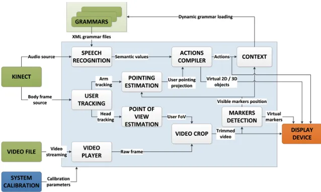
Figure 2. System components.
Additionally, the system integrates the recognition of voice commands to trigger actions related to the marker activated by the pointing action (Figure 1). Kinect is responsible of grabbing the user’s voice through its microphone array and a specific grammar built from the scene is available for the user to disambiguate the choice when multiple action options are available for the same object. E.g. when pointing at a car, the viewer will be able to opt between e.g. traffic information and boarded pollution sensors through voice commands.
B. Overall architecture
Figure 2 shows the overall architecture of the system. The
video player decodes the input video file to obtain the complete raw frames that are trimmed in the video crop module depending on the user’s point of view, and then rendered in the display device. Additionally, each trimmed video frame is processed in the markers detection module to dynamically recognize pre-established patterns and create virtual objects to represent those markers along with the trimmed video frame.
The user tracking module processes the Kinect’s body frame source to recognize and track the user’s head and arm and submit those data to the estimation modules to estimate both the user’s point of view and the pointing vector. The former is used, as mentioned above, by the video crop module to trim the video frame according to the user’s subjective point of view, whereas the latter detects whether the user is pointing to a visible marker in the region of video frame that is being displayed. Markers are defined within the marker detectionmodule. This information is used by the actions compiler module to trigger actions linked to the pointing of the user at the markers, e.g. creating virtual 2D/3D objects related to the markers or superimposing data.
Finally, the speech recognition module processes the Kinect’s audio source and, depending on the grammar that is currently loaded, sends the recognized voice command to the actions compiler, in order to perform the action linked to that speech command. Both the performed actions and the visible markers are defined by the application context, which
dynamically changes the loaded grammar into the speech recognizer to define the commands that can be interpreted.
IV. KEY ARCHITECTURE MODULES
After the review of the general architecture, we following comment on the two modules that make possible, in practice, the Virtual Window to be interactive: the pointing estimation and the video marker detection components.
A. Pointing estimation component
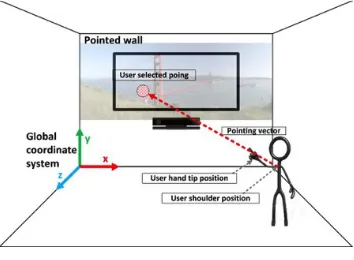
The pointing estimation component is in charge of estimating the 2D coordinates the user is pointing at. Kinect device provides the user’s arm joints positions which enable to calculate the pointing vector that, once projected into the target 2D plane, will deliver the desired coordinates (Figure 3). In the Interactive Virtual Window, the target 2D plane will be the display infrastructure that serves to simulate the window.
The pointing estimation logic handles multiple coordinate systems. First of all, the Kinect camera captures the user’s joints positions referred to the camera coordinate system (Figure 4-a). The user’s arm pointing vector is estimated from the shoulder joint position and hand-tip position delivered by Kinect. Both positions will be transformed to Kinect coordinate system (also called “skeleton coordinate”, Figure 4-b), which is the 3D coordinate system defined by the Kinect SDK. Its origin is located at the center of the IR sensor on the Kinect device. Although both camera and Kinect coordinate systems are right-handed, the first one is rotated around Z axis for 180 degrees with respect to the second.
When a real scene is reconstructed, the resulting 3D coordinates are relative to a certain point at the scene. So, to perform the subsequent transformation, a calibration pattern-based coordinate system (Figure 4-c) is needed; this new coordinate system will have its origin in the calibration pattern (calibration is mandatory). The transformation between the coordinates referenced to Kinect coordinate system to the
previous calibration process. This stage of the process includes the use of a new reference system, called the global coordinate system (Figure 4-d). It is employed to reference the points to the real 3D space and makes possible to position objects in the room. The transformation to this global coordinate system is calculated by making a rotation of axis and a translation, which corresponds to the distance between the origins of both coordinate systems (in the global coordinate system).
Figure 3. Pointing estimation.
At the fourth transformation, the system needs to project the pointing vector, referred to the global coordinate system, to the target projection plane. This plane has a predefined coordinates in the global coordinate system, concretely it is null in Z. The projection result will deliver the coordinates (xpG, ypG).
Figure 4. Scheme with the relations to the coordinates transformations between the existing coordinate systems.
In order to perform Kinect camera calibration, we have used Calibration toolbox for Matlab [19], following the process described at [2][3]. The resulting parameters are divided within two groups, intrinsic and extrinsic parameters. Extrinsic parameters estimate the location and the orientation of the camera in the real space; they are obtained from the camera intrinsic parameters. Intrinsic parameters (e.g. principal axis, optical center and focal distance) are related to the internal geometry and the optical features of the camera and remain constant if the features and relative positions of the optics and the imaging sensor do not vary. With respect to the calibration pattern, we have used a chessboard of 5x5 60 mm-sided squares. Kinect camera has taken 21 images with the operational calibration pattern in different positions and poses, in order to extract the camera intrinsic parameters.
B. Video marker detection module and display management
Another key aspect of the Interactive Virtual Window is how to deal with the automatic recognition and classification of objects in the video the user is looking at. This problem has been widely handled from different approaches in diverse fields such as traffic monitoring [20], surveillance [21] or Augmented Reality [22]. E.g. in [23] it is applied a biologically inspired model of visual object recognition to satisfactorily categorize
multiple objects in natural images, although the system is not real-time. Both [24] and [25] describe different approaches to the problem of object class recognition in photographs, validating their models through different image databases. In [26], a method is proposed for object recognition and classification on a real-time video stream, with the limitation that only the moving targets are taken into consideration.
In this first version of the Interactive Virtual Window, we have chosen a simple but functional approach to detect and classify object types in video streaming. As the Window initially uses a pre-recorded video, we have opted for a manual configuration of the markers in a pre-visualization stage. Although this work is tedious, it allows to define with great accuracy whatever object or area in the video, avoiding misrecognition problems. This is important at this stage of the prototyping, as our next goal is to validate user experience, thus we have to keep error sources under control.
Figure 5. Definition and real-time visualization of video markers.
Thus, to define a marker it is necessary to specify both the coordinates of the polygon that enclose the marker and the frames in which the shape is valid, as it is depicted in the upper part of Figure 5. This allows us to have multiple markers that can change not only the position but also shape along the time. The definition of those markers is stored in an XML file, following the sample structure showed in Figure 6. The root node of the XML file, called <markers>, has as many <marker> child nodes as there are video markers. Each of those <marker> nodes has a compulsory attribute, called tag, which uniquely identifies that marker. It also has one or more <frames> child nodes, to specify all the different positions and time intervals of each marker. The child nodes <from> and <to> inside the <frames> node indicate the indices of the start and end frames where the marker is valid following the shape defined in the child node <polygon>. The shape is defined as a collection of two-dimensional coordinates representing the vertices that compose the polygon. Once the video markers are defined, the user can interact with them in real time. As is it shown in the bottom part of Figure 5, depending on the user’s point of view, the active markers will differ.
video frame that is being visualized and their screen coordinates is known. Thus, it is now feasible to calculate which pixel in the video frame is the point the user is pointing at. Finally, we can check if that pixel belongs to any of the markers defined in the XML file, and trigger the corresponding action.
Figure 6. XML file sample for video markers definition.
V. CONCLUSIONS
The proposed system aims at delivering a real multimodal interaction linked to a Virtual Window. Still a prototype with limited functionalities, the concept is applicable to different service scenarios, which may include learning, remote control or monitoring, and teleconference. Regarding technical aspects, the automatic and real time recognition of interaction markers in the video streams (both recorded or live) can be significantly improved to ensure service diversity (i.e. to facilitate the inclusion of new videos or streaming). Another fundamental issue is the construction of a sound user experience; to do so, it is necessary to carry out dedicated user studies in which the interaction concept and the technology performance can be evaluated. That is our next goal, to analyze how the user feels when using the Interactive Virtual Window concept, in order to study aspects such as fatigue, control feeling and acceptance.
ACKNOWLEDGMENTS
This work has been supported by the Spanish Ministry of Economy and Competitiveness under grant TEC2014-55146-R.
REFERENCES
[1] A. Jaimes and N. Sebe, “Multimodal human–computer interaction: A survey,” Comput. Vis. Image Underst., vol. 108, 1–2, 116–134, 2007. [2] J. A. Besada, J. M. Rodera, A. M. Bernardos, J. I. Portillo, and J. R.
Casar, “Design and user experience assessment of Kinect-based Virtual Windows,” J. Ambient Intell. Humaniz. Comput., vol. In press. [3] A. Fernández, L. Bergesio, A. M. Bernardos, J. A. Besada, and J. R.
Casar, “A Kinect-based system to enable interaction by pointing in smart spaces,” Procs. IEEE Sensors Applications Symposium, 2015.
[4] H. Fürntratt and H. Neuschmied, “Evaluating Pointing Accuracy on Kinect V2 Sensor,” Procs. Intl. Conf. on Multimedia and Human-Computer Interaction, 2014.
[5] M. Henschke, T. Gedeon, and R. Jones, “Extending the index finger is worse than sitting: Posture and minimal objects in 3D pointing interfaces,” Procs. IEEE 4th International Conference on Cognitive Infocommunications, pp. 797–802, 2013.
[6] K. Watanabe, Y. Miyake, N. Nakamichi, T. Yamada, and T. Ozeki, “Remote Touch Pointing for Smart TV Interaction,” Procs. IEEE Global Conference on Consumer Electronics, pp. 232–235, 2014. [7] S. S. Raza Abidi, M. Williams, and B. Johnston, “Human Pointing As a
Robot Directive,” Procs. ACM/IEEE International Conference on Human-robot Interaction, pp. 67–68, 2013.
[8] L. Gallo, A. P. Placitelli, and M. Ciampi, “Controller-free exploration of medical image data: Experiencing the Kinect,” Procs. Intl. Symp. on Computer-Based Medical Systems, pp. 1–6, 2001.
[9] H. Kim, Y. Kim, D. Ko, J. Kim, and E. C. Lee, “Pointing Gesture Interface for Large Display Environments Based on the Kinect Skeleton Model,” in Future Information Technology, 2014, 509–514. [10] C. J. Lin, S.-H. Ho, and Y.-J. Chen, “An investigation of pointing
postures in a 3D stereoscopic environment,” Appl. Ergon., vol. 48, pp. 154–163, 2015.
[11] S. Achmiz and D. Bolchini, “NUICursorTools: Cursor Behaviors for Indirect-pointing,” Procs. International Working Conference on Advanced Visual Interfaces, pp. 331–332, 2014.
[12] E. Schapira and R. Sharma, "Experimental Evaluation of Vision and Speech based Multimodal Interfaces", Procs. of the 2001 workshop on Perceptive user interfaces. ACM, 2001.
[13] “Kinect Fun Labs,” Kinect Fun Labs. Available:
http://marketplace.xbox.com/en-US/Product/Kinect-Fun-Labs/66acd000-77fe-1000-9115-d80258480811?nosplash=1.
[14] C.-C. Huang, R.-H. Liang, L. Chan, and B.-Y. Chen, “Dart-It: Interacting with a Remote Display by Throwing Your Finger Touch,” in ACM SIGGRAPH 2014 Posters, pp. 46, 2014.
[15] A. Biskupski, A. R. Fender, T. M. Feuchtner, M. Karsten, and J. D. Willaredt, “Drunken Ed: A Balance Game for Public Large Screen Displays,” in Procs. CHI ’14 Extended Abstracts on Human Factors in Computing Systems, pp. 289–292, 2014.
[16] A. Zaranek, B. Ramoul, H. F. Yu, Y. Yao, and R. J. Teather, “Performance of Modern Gaming Input Devices in First-person Shooter Target Acquisition,” Procs. Extended Abstracts on Human Factors in Computing Systems, pp. 1495–1500, 2014.
[17] K. M. Gerling, K. K. Dergousoff, and R. L. Mandryk, “Is Movement Better?: Comparing Sedentary and Motion-based Game Controls for Older Adults,” in Proc. of Graphics Interface, pp. 133–140, 2013. [18] VIEW, http://www.grpss.ssr.upm.es/index.php/es/videos/video/view [19] J. Heikkila and O. Silven, “A four-step camera calibration procedure
with implicit image correction,” Procs. IEEE Computer Society Conf. on Computer Vision and Pattern Recognition, 1106–1112, 1997. [20] B. Morris and M. Trivedi, “Robust classification and tracking of
vehicles in traffic video streams,” Procs. IEEE Intelligent Transportation Systems Conference, pp. 1078–1083, 2006.
[21] I. Haritaoglu, D. Harwood, and L. S. Davis, “W4: real-time surveillance of people and their activities,” IEEE Trans. Pattern Anal. Mach. Intell., vol. 22, no. 8, pp. 809–830, 2000.
[22] E. N. G. Weng, R. U. Khan, S. A. Z. Adruce, and O. Y. Bee, “Objects Tracking from Natural Features in Mobile Augmented Reality,” Procedia - Soc. Behav. Sci., vol. 97, pp. 753–760, Nov. 2013. [23] J. Mutch and D. G. Lowe, “Multiclass Object Recognition with Sparse,
Localized Features,” in 2006 IEEE Computer Society Conference on Computer Vision and Pattern Recognition, vol. 1, pp. 11–18, 2006. [24] R. Fergus, P. Perona, and A. Zisserman, “Object class recognition by
unsupervised scale-invariant learning,” Procs. IEEE Computer Society Conference on Computer Vision and Pattern Recognition, vol. 2, pp. II–264–II–271, 2003.
[25] J. Shotton, J. Winn, C. Rother, and A. Criminisi, “TextonBoost for Image Understanding: Multi-Class Object Recognition and Segmentation by Jointly Modeling Texture, Layout, and Context,” Int. J. Comput. Vis., vol. 81, no. 1, pp. 2–23, 2007.
[26] A. J. Lipton, H. Fujiyoshi, and R. S. Patil, “Moving target classification and tracking from real-time video,” Procs. IEEE Workshop on Apps. of Computer Vision, pp. 8–14, 1998.
<markers>
<marker tag="WEATHER"> <frames>
<from>1</from> <to>M</to>
<polygon>xw1, yw1, xw2, yw2, xw3, yw3, xw4, yw4</polygon>
</frames> <frames>
<from>M+1</from> <to>N</to>
<polygon>xw1', yw1', xw2', yw2', xw3', yw3', xw4', yw4'</polygon>
</frames> </marker>
<marker tag="TRAFFIC"> <frames>
<from>1</from> <to>M</to>
<polygon>xt1, yt1, xt2, yt2, xt3, yt3, xt4, yt4, xt5, yt5</polygon>
</frames> </marker>
<marker tag="BOAT"> <frames>
<from>M+1</from> <to>N</to>
<polygon>xb1, yb1, xb2, yb2, xb3, yb3</polygon>