IJSRR, 8(2) April. – June., 2019 Page 2462
Research article Available online www.ijsrr.org
ISSN: 2279–0543
International Journal of Scientific Research and Reviews
“Design, Fabrication, and Development of Hydraulic Sky Lifter
For Two Wheelers”
Samarth J. Shelat
*1, Pavan Mistry
2, Ankit Tiwari
3, Divy Patel
4, Dharmik Patel
51
Assistant Professor, Department of Automobile Engineering, A. D. Patel Institute of Technology, New V.V. Nagar, Anand-388121, Gujarat, India
Email: [email protected]
2, 3, 4, 5
Final Year Students,Department of Automobile Engineering, A. D. Patel Institute of Technology, New V.V. Nagar, Anand-388121, Gujarat, India
Email:[email protected]; [email protected];[email protected]; [email protected]
ABSTRACT
The following research paper describes the design as well as fabrication of a hydraulic Sky lifter on Two wheeler. We short out the problem that was happened service stations and workshops. There was major issue regarding the lifting of bikes. There were jacks available but they can lift the bike in only one position. This causes fatigue to the workers as well as difficulty in reaching the parts of the bike during servicing. So for this problem we can up with the idea that we should construct a lifting machine that will be able to lift the bike in different positions so that the worker can easily to perform the servicing procedure simply. In addition to this, the lifting machine will be able to lift the bike in three different positions. They are ‘both wheel high’, ‘front wheel high’ and ‘rear wheel high’. So in this way the worker will be able to work more easily and efficiently. This hydraulic Sky Lifter will be able to lift bikes using minimal effort. This will be beneficial for the servicing point of view, so it is in much need for the service stations as well as workshops. This lifting machine will also reduce the fatigue of the operator during the servicing of the bike and it will result in benefit of operator and service station. This paper describes the complete study of components, selection of materials, Considers the dimensions of components along with their sketches with the help of Design software. Further fabrication of all the parts and assembly is carried out.
KEYWORDS:Hydraulics, Sky Lifter, Two Wheeler, Superbikes, Ramp
*Corresponding author:
Samarth Jayeshbhai Shelat
Assistant Professor in Automobile Engineering Department
A.D. Patel Institute of Technology, New V.V. Nagar,
Anand-388121, Gujarat, India.
IJSRR, 8(2) April. – June., 2019 Page 2463
LITERATURE REVIEW
Ghangale Prashal et al., described the design and analysis of hydraulic scissor lift. Lift was
needed to be designed portable and also work without consuming any electric power therefore
cylinder was actuated by using hydraulic hand pump. Also such design can make much suitable for
medium scale work1. Sabde Abhijit Manohar rao and Jamgekar R. S., investigated the problem at DS
Engineers regarding hydraulic scissor lift. It was found that job to be lifted is heavier which causes
more deformations in hydraulic lift frame hence, checking deformations and stress induced in it was
the major objective of this project. Also weight of the lift was high so weight optimization was prime
objective of this project. As loading & unloading is repeated there were chances of fatigue failure so
life of lift was checked. Thus Design& Analysis of the Hydraulic lift that should with stand
maximum load without failure in working conditions and checking vibration of hydraulic lift during
working time by modal analysis was carried out2. Described and focused on force acting on the
hydraulic scissor lift when it is extended and contracted. A hydraulic scissor lift was used for lifting
and holding heavy weight components. Material selection plays a key role on designing a machine
and also influence on several factor such as durability, reliability, strength, resistance which finally
leads to increase the life of scissor lift3.SabdeAbhijitManoharrao and Jamgekar R.S. described that A
hydraulic pallet lift is a mechanical device used for various applications for lifting of the loads to a
height or level. A lift table is defined as a scissor lift used to stack, raise or lower, convey and/or
transfer material between two or more elevations. The main objective was the devices used for lifting
purposes is to make the table adjustable to a desired height. A scissor lift provides most economic
dependable & versatile methods of lifting loads; it has few moving parts which may only require
lubrication. This lift table raises load smoothly to any desired height. It is found that they are facing
some problems regarding hydraulic scissor lift like job to be lifted are heavier which causes more
deformations in hydraulic lift frame checking deformations & stresses induced in it is a major
objective of this project. It is also found that weight of the present lift is high weight optimization is
also prime objective of this project. Design & Analysis of the Hydraulic lift that should with stand
maximum load without failure in working conditions. To check vibration of hydraulic lift during
working time by modal analysis4.UbaleDivyeshPrafulla, et al. described with conventional method of
rope using, ladder lift getting person to a height encounter a lot of limitation also there may be a risk
of falling down in case of ladders hence hydraulic scissors lift is designed to overcome all these
difficulties. Paper reviewed that design and analysis and to construct a multiutility home equipment
for senior citizens so that they can carry their daily activities efficiently. Also the equipment should
be compact and cost effective. Lifting height achieved by scissor mechanism is of 1 m from bottom
IJSRR, 8(2) April. – June., 2019 Page 2464
different parts of hydraulic scissor lift and the material used for that part as per the mechanical
properties of that material like ductility, strength, toughness, hardness etc. Also they have discussed
all the design concepts for the different parts of the lift. Then the analysis was carried out by using
Ansys software in which parameters like Deformation, Von misses stress, Shear stress were
analysed. They have done the design and fabrication of hydraulic scissor lift including Ergonomics,
Material handling as well as comfort6.P S K Narasimha Murthy et. al. has done modelling and
analysis (Linear Static) of a scissor lift which is carried out using Solid Works. Whenever a load is
applied on the top of the platform, every post leg of the lift is subjected to displacement, stress, and
strain. In this project result of the displacement, stress and strain values, and their behaviour are
tabulated 7.
INTRODUCTION
Introduction to Hydraulics
Hydraulics, branch of science concerned with the practical applications of fluids, primarily
liquids, in motion. It is related to fluid mechanics, which in large part provides its theoretical
foundation. Hydraulics deals with such matters as the flow of liquids in pipes, rivers, and channels
and their confinement by dams and tanks. Some of its principles apply also to gases, usually in cases
in which variations in density are relatively small. Consequently, the scope of hydraulics extends to
such mechanical devices as fans and gas turbines and to pneumatic control systems. Liquids in
motion or under pressure did useful work for man for many centuries before French
scientist-philosopher Blaise Pascal and Swiss physicist Daniel Bernoulli formulated the laws on which
modern hydraulic-power technology is based8.
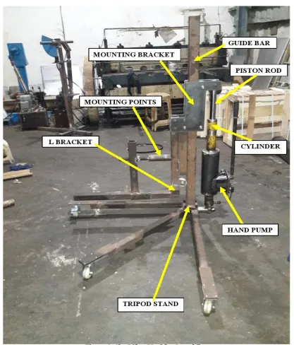
Introduction to hydraulic Sky Lifter
Hydraulic sky lifter uses the concept of Pascal’s law for the purpose of lifting the bikes. In
this structure, hand pump is used to generate pressure in the hydraulic cylinder. The hydraulic
cylinder consists of oil which when pressurized results in lifting of the bike. Along with the cylinder
there is a guide bar, which serves the purpose of controlling the height up to which the bike can be
lifted. The guide bar lets the bike to be lifted up to 3-4 ft. height. When the bike gets lifted, the
motion of the guide bar can be locked and can fully offload the bike from the cylinder. The structure
consists of three base channels. These channels support the structure as the load gets differentiated
between the three channels. Then there are rollers available which help to manoeuvre the bike and
can move the bike from one place to another with the minimal effort. When it comes to lifting the
IJSRR, 8(2) April. – June., 2019 Page 2465
bikes. For the safety purpose, straps are there which locks the movement of the bike. This allows the
worker to operate on the bike safely.
TYPES OF SKYLIFTER & THEIR METHODOLOGY:
There are different types of sky lifters. Sky lifters can be classified on the basis of mounting that
can be used. They are:
1.
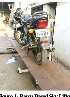
Ramp Based Sky Lifter
Figure 1: Ramp Based Sky Lifter
This is a unique kind of lifter which is fabricated by us. This system consists of single acting
hydraulic cylinder which lifts the ramp up to 2-3 feet height. It also consists of tripod stand which
divides the load into 3 parts so that weight distribution is done properly, also consists of industrial
rollers which can manoeuvre i.e. the whole system can be moved to and fro and can be rotated. The
weight and the cost of the system is much lower than the scissor lifts. The ramp is modular type
which can be detachable. The speciality of this skylight is every component is detachable and can be
attached by simple bolting, this causes ease of work.
Step’s for Hydraulic Sky Lifter (Ramp Based Sky Lifter):
As the system’s each and every part is detachable(bolted) there are certain steps for attachment
of each parts of the sky lifter. The following steps are as follows:
- Setup the tripod base and bolt the industrial roller so that the base can move and rotate.
Now bolt the column of 1330 mm with Allen bolts. A complete tripod stand will be scene.
From drawing at a distance of 115mm from junction the tank cylinder unit is mounted on the pin
and the pin is inserted in the hole.
Similarly referring the drawing, the template, roller, the L-bracket are mounted as a unit via
IJSRR, 8(2) April. – June., 2019 Page 2466 Now the modular ramp is assembled. The ramp is made of several box channel i.e. 40mm,
50mm, 60mm and all are inserted in one another.
Thus the whole ramp assembly is inserted and bolted in 50mm L-Bracket and on the ramp the
wheel chocks are inserted for immobile the motorbike wheels.
2.
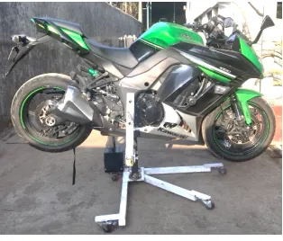
Sky Lifter for Superbikes
Figure 2:Mounting Based Sky Lifter This type of sky lifter consists of the following features.
The Horizontal lifting position allows you to simply raise the bike with both wheels’ level like a
traditional bench lift.
The Rear wheel high (stop position) is perfect for working on the rear end of the bike and allows
access to areas on your bike you would have struggled to get to before. This will raise the rear
end of the bike higher off the ground than most workbench's.
The Front wheel high (wheelie position) will raise the bikes front wheel to around eye level
taking the back ache out of front end maintenance and cleaning. This will raise the front end of
the bike higher off the ground than most workbench's!
The Sky Lift requires no modifications or parts to be permanently fitted to your bike
whatsoever, your machine stays totally standard. The lift fits to the swing arm pivot of the
motorcycle and connects at the rear of the swing arm via a support strap (depending on lifting
position). Should you change your motorcycle it’s a simple case of upgrading your fitting kit for
your new machine, fittings can be changed for different models in a matter of seconds and are
relatively cheap to purchase.
Step for Hydraulic Sky Lift (Sky Lifter for Superbikes):
The assembly procedure for the sky lift is same from the above one up to the steps 4.
Setup the tripod base and bolt the industrial roller so that the base can move and rotate.
Now bolt the column of 1330mm with Allen bolts. A complete tripod stand will be scene.
From drawing at a distance of 115mm from junction the tank cylinder unit is mounted on the pin
IJSRR, 8(2) April. – June., 2019 Page 2467 Similarly referring the drawing, the template, roller, the L-bracket are mounted as a unit via
bolting this sub-assembly is assembled around the column.
In this system an another component is assembled similar to L-Bracket consisting of cylindrical
mounting points on both the L-Bracket which is bolted with the template and another is inserted
in 50mm box channel.
The two cylindrical mounting points are mounted opposite to each other and the left handed
L-bracket is moving so as to compensate the track of the bike.
There are basically three main components i.e. a hydraulic cylinder and hand operated pump
which will lift the bracket having mounting points where the bike is mounted through S shaped
bracket which will connect the piston and the bike mounting bracket.
The height is equal to the stroke of the piston the height is decided according to nominal working
area where the labour could do his work easily.
Fitting starts with standing the bike upright and inserting the point in swing arm pivot. The sky
lifter supports the bike securely by both swing arm pivots. To lift the bike in horizontal position
the lifting strap is connected with the swing arm and a secondary locking buckle is fitted for
additional security with the help of hand pump the bike can have lifted and when it reaches its
extreme position it can be locked to fully offload the hydraulic pump.
The high quality casters with brake allows to move the bike in any position with slight effort thus
the bike is very safe and secure. To bring back the bike on ground position the pressure valve is
released of the hydraulic cylinder.
Now to lift the bike in wheelie position allows to work in hard to reach areas at front end, this
can be done by tying the lock buckle to the frame and the bike rear end thus we get the wheelie
position with good variability.
Now to lift the bike in rear wheelie position allows to work in rear based hard to reach areas this
can be done simply by raising the bike without the lock buckle as due bike weight this position is
required.
P
ROBLEM & SOLUTION OF HYDRAULIC SKYLIFTER
The problem we were facing was that earlier the hydraulic sky lifter which was used was
lifting only heavy weight bikes. This was possible because the superbikes were available with the
mounting points which can be used to lift superbikes. But when it comes to the conventional bikes,
this system failed as there was unavailability of the mounting points in these kind of bikes. As our
main purpose of this project was to make the lifting machine for all kind of bikes, so we must make
IJSRR, 8(2) April. – June., 2019 Page 2468
For the problem described earlier, we came up with an idea that we can make a structure which can
be used for superbikes as well as the conventional bikes. This task was achieved by introducing a
ramp in the structure, whenever the bike is to be lifted it can be achieved by simply riding it to the
ramp and then can be lifted with the help of the hand pump. After consulting the industry, we had
done further optimization that will be beneficial for company point of view. We planned to make 2
in 1 system that will consist of mounting point as well as the ramp. Those dealers which require both
the applications they will get the 2 in 1 system and those which require only one, i.e. either mounting
point system or with the ramp, they will also get benefitted. In this way this product will be of higher
use for the dealer’s view also.
MATERIALS USED FOR SKY LIFTER
Structural Steel (Grade IS226)
60X60X4 Box tube
50X50X3.5 Box tube
40X40X4 Box tube
PU (Plastic) rollers
4 Industrial rollers (2 with brakes)
Hydraulic cylinder tube CS
Hydraulic Oil 65(Viscosity 68 centistokes at 40 degree oC, density 865kg/m3)
Piston rod EN8
Hard chrome 50 micron on diameter
Chrome hardness 58RC
Structural steel has high strength to weight ratio which means it has high strength per unit
mass. It is also cheap when compared with other materials. Box tubes have higher yield and
tensile strength which allows is to withstand higher pressure, temperature and destructive
elements. It is also cost effective.
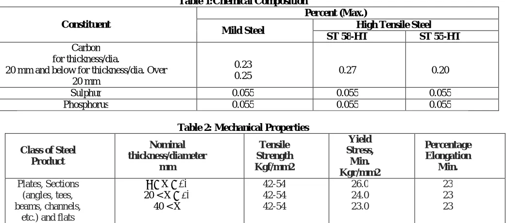
The material used is Structural Steel IS226 and the following tables represents its chemical,
IJSRR, 8(2) April. – June., 2019 Page 2469
Table 1:Chemical Composition Constituent
Percent (Max.)
Mild Steel High Tensile Steel ST 58-HT ST 55-HT
Carbon for thickness/dia.
20 mm and below for thickness/dia. Over 20 mm
0.23
0.25 0.27 0.20
Sulphur 0.055 0.055 0.055
Phosphorus 0.055 0.055 0.055
Table 2: Mechanical Properties Class of Steel
Product Nominal thickness/diameter mm Tensile Strength Kgf/mm2 Yield Stress, Min. Kgr/mm2 Percentage Elongation Min. Plates, Sections (angles, tees, beams, channels,
etc.) and flats
σ ≤ X ≤ 20
20 < X ≤ 40
40 < X
42-54 42-54 42-54 26.0 24.0 23.0 23 23 23
Table 3: Comparison Between Mild Steel and High Tensile Steel
Sr.
No. Origin
High Tensile Steel Standard Steel No. of standard Ultimate tensile stress Minimum Yield stress Minimum elongation % No. of standard Ultimate Tensile strength Minimum yield stress Minimum elongation %
1 India IS:961
1975 58 36 20
IS:961
1975 42-54 23-26 23
2 USSR CT5
20L2 50-62 28 15-21 CT4 45-52 26 19-25 3 Italy UNI 50-60 34-38 22 UNI 37-45 24-28 25
4 UK BS:548
1934 58-68 30-36 14
BS:15
1948 44-52 23-24 16-20
DESIGN & CALCULATION FOR SKY LIFTER
Let, weight of the bike is 200kg.
W = 200*9.8 = 1960 N
1. Modulus of Elasticity of mild steel
E = 2.06 * 10 N/mm2
2. Moment of inertia of square
I = b
12
= (60)
12
IJSRR, 8(2) April. – June., 2019 Page 2470 3. For the L bracket
Slope at free end
θ = Wl²
2EI
= (1960) (645) ²
2(2.06 * 10³) (1080000)
= 1.83 * 10ˉ³ mm
4. For the mounting points
In the case of the right hand side mounting point,
Bending moment = F*d
= 1960 * 150
= 294000 N.mm
Bending stress = Moment * y
I
= 294000 * 17.5
1080000
= 47.6 N/mm²
Now, in the case of mounting point on the left hand side, as it is movable so we considered
to take 40% of the overall length of the mounting point, i.e. 40% of 250 = 100 mm.
Bending moment = F * d
= 1960 * 100
= 196000 N.mm
Bending stress = Moment * y
I
= 196000 * 17.5
1080000
= 31.76 N/mm²
5. For the guide bar
As the guide bar is in attachment with the L bracket, so the highest load will be applied on the
guide bar only. In addition to the guide bar, the overall weight including the weight of the bike will
be applied on the guide bar.
IJSRR, 8(2) April. – June., 2019 Page 2471
Θ = Wl³
3EI
= (1960) (1330) ³
2(2.06 * 10 ) (1080000)
= 6.908 mm
Bending moment = F*d
= 1960 * 645
= 1264200 N.mm
Bending stress = Moment * y
I
= 1264200 * 30
1080000
= 35.11 N/mm²
6. Hydraulic cylinder capacity
Force=area x pressure
Ex. 50x35x550 St.
A = ∏ x r²
= 3.142x 2.5x2.5
=19.63 x 100
= 1963.75÷1000
=1.96-ton force.
DESIGNING OF SKY LIFTER (SETUP)
As per requirement, the specifications are as;
Material: Mild Steel
Structure: Box section (50mm X 50 mm)
Ramp Size: 2200 X 550 X 25 mm
Oil tank capacity: 1.05≈2 litres
Cylinder volume: 1.07 litres
Push force at 100 kg: 1.96 ton
Oil: Hydraulic 68
Hydraulic cylinder with hand pump: 50 X 35 mm
IJSRR, 8(2) April. – June., 2019 Page 2472 Oil tank capacity: 1.05≈2 litres
Cylinder volume: 1.07 litres
Push force at 100 kg: 1.96 ton
Oil: Hydraulic 68
Hydraulic cylinder with hand pump: 50 X 35 mm
Single acting port 1/2” bsp
Figure 3: Sky Lifter Used for Superbikes
CONCLUSION AND SUMMARY
The problem was that in service stations there was major issue regarding the lifting of bikes.
IJSRR, 8(2) April. – June., 2019 Page 2473
workers as well as difficulty in reaching the parts of the bike during servicing. So for this problem
we can up with the idea that we should construct a lifting machine that will be able to lift the bike in
different positions so that the worker can perform the servicing procedure easily. Hydraulic sky lifter
uses the concept of Pascal’s law for the purpose of lifting the bikes. In this structure, hand pump is
used to generate pressure in the hydraulic cylinder. The hydraulic cylinder consists of oil which
when pressurized results in lifting of the bike. Along with the cylinder there is a guide bar, which
serves the purpose of controlling the height up to which the bike can be lifted. The guide bar lets the
bike to be lifted up to 3-4 ft. height. When the bike gets lifted, the motion of the guide bar can be
locked and can fully offload the bike from the cylinder. The structure consists of three base channels.
These channels support the structure as the load gets differentiated between the three channels. Then
there are rollers available which help to manoeuvre the bike and can move the bike from one place to
another with the minimal effort.
The problem we were facing was that earlier the hydraulic sky lifter which was used was
lifting only heavy weight bikes. This was possible because the superbikes were available with the
mounting points which can be used to lift superbikes. We came up with an idea that we can make a
structure which can be used for superbikes as well as the conventional bikes. This task was achieved
by introducing a ramp in the structure, whenever the bike is to be lifted it can be achieved by simply
riding it to the ramp and then can be lifted with the help of the hand pump. After consulting the
industry, we had done further optimization that will be beneficial for company point of view. We
planned to make 2 in 1 system that will consist of mounting point as well as the ramp. Those dealers
which require both the applications they will get the 2 in 1 system and those which require only one,
i.e. either mounting point system or with the ramp, they will also get benefitted.
We came across the issue regarding the servicing of the bikes. For this issue, the solution came a
hydraulic sky lifter, which will be able to lift the bike in different positions. Then for the dealer point
of view, we came up with the structure that can be operated 2 in 1 system. Because some dealer’s
requirement is to use only mounting purpose and some dealer’s requirement is to use Ramp for
general use but some service agencies is to use multipurpose like which we had designed to use in
multirole as Ramp as well as mounting purpose.
REFERENCES
1. GhangalePrashal, BhorShubham, et. al. Design Analyasis and Manufacturing of Portable
Hydraulic Sissor Lift. Global Journal of Engineering Science and Researches. 2017;92-97.
2. SabdeAbhijitManoharrao and Jamgekar R. S. Analysis & Optimization of Hydraulic Scissor
IJSRR, 8(2) April. – June., 2019 Page 2474
3. M. Kiran Kumar, J. Chandrasheker, et. al. Design & Analysis of Hydraulic Scissor Lift.
Research Journal of Engineering and Technology, 2016; 3(6): 1647-1653.
4. Sabde Abhijit Manoharrao and Jamgekar R.S. Design and Analysis of Hydraulic Scissor Lift
By FEA, International Research Journal of Engineering and Technology (IRJET), 2016;
3(10): 1277-1292.
5. Ubale Divyesh Prafulla, Alan Francy, et al. Design, Analysis and Development of
Multiutility home equipment usingScissor Lift Mechanism., International Journal of scientific
research and management, 2015; 3(3): 2405- 2408.
6. Momin G. G., Hatti Rohan, et. al. Design, Manufacturing & Analysis of Hydraulic Scissor
Lift, International Journal of Engineering Research and General Science 2015; 3(2): 733-740.
7. P S K Narasimha Murthy, D VinodPrabhakara Rao, et. al. Modeling and Analysis (Linear
Static) on a Scissor Lift”, IJMEIT, 2014; 2(9):754-759.