SPOTSprojectanddevelopmentofastandardandreferencematerial
Richard Burguete1, Eann Patterson2a
1
Airbus UK, Filton House, Bristol, UK
2
Department of Mechanical Engineering, Michigan State University, East Lansing, MI, USA
Abstract. The ‘Standardization Project for Optical Techniques of Strain measurement’ (SPOTS) was focused on the development of reference materials for calibrating optical systems for static strain measurement and standardized tests for evaluating the capabilities of such systems. The reference material consists of a beam in four-point bending within a monolithic frame that ensures reproducibility of the boundary and loading conditions. A procedure for the use of the reference material has been developed and leads to the evaluation of measurement uncertainties that allow the construction of confidence limits for the data obtained with the calibrated optical system. The design and methodology have been developed into a proposed draft standard which is being endorsed by VAMAS (Versailles Agreement on Materials And Standards) for review by ISO (International Standards Organisation). An overview of philosophy underpinning the proposed draft standard is presented and serves as an introduction to the reference material and standardized test and their use in providing higher confidence in optical measurements of strain.
1 Introduction
1.1 Engineering context
The design process for engineering components and structures involves a series of decisions associated with optimising functional performance, minimizing costs and maximizing aesthetical appeal while achieving structural integrity. The quality of these decisions is dependent on the quality of the data available to the engineer which in the case of structural integrity includes information about the service loads to which the component or structure will be subjected and the stress levels that such loads will induce. It is common practice to predict the stress levels using simulations of designs based on numerical modelling techniques such as finite element analysis or boundary element analysis. The quality of data generated from these simulations is strongly dependent on the accuracy of the material model, the idealisation of the boundary conditions including the applied loads and the representation of the geometry in which discretization plays a major role in determining the reliability of the model. Schwer [1] has explained the need for both verification and validation of simulations in computational solid mechanics. In this context verification is defined in two parts: code verification in which errors in the computer program are
a
email: [email protected]
eliminated; and calculation verification in which the numerical errors arising from discretization are estimated. Thus when employing a commercially available modelling code, such as a finite element package, the majority of the code verification will have been performed by the company supplying the package and in a good package it will be difficult for the operator to generate logic or programming errors during the building of model. However, the operator will have to estimate the errors arising from their chosen discretization and techniques such as convergence studies are frequently used. Validation is defined as ‘the process of determining the degree to which a model is an accurate representation of the real world from the perspective of the intended uses of the model’ [1]. The key to validation is the conduct of experiments specifically designed to generate results that can be compared to results from the model and as a consequence the quality of the validation is dependent on being able to assess the accuracy of the experimental results and quantify the uncertainty associated with them. Verification of numerical models is probably more frequently performed than validation because it can be self-contained within the simulation process and does not need to involve experiments which are perceived to be expensive, difficult to perform and introduce additional uncertainty. In practice, experiments are expensive, can be difficult to perform and allow uncertainties to be defined and known; however failure to conduct experiments for the purpose of validation may be more expensive and lead to greater difficulties as a consequence of uncertainties or errors being undefined and hidden. A traditional approach to validation of numerical models has been to identify the maximum or ‘hot-spot’ of stress from the results of the simulation and to use a strain gauge applied to a physical prototype to measure the corresponding strain. Such an approach, whilst better than no validation at all, is often insufficient since it assumes that the numerical model has correctly identified the largest maximum stress and that there is not an ‘unseen’ one elsewhere from which failure would initiate. It is also inadequate if the model is subsequently used to reduce the weight of a component by removing material from areas of predicted zero or close to zero stress; since the prediction in these areas has not been validated and could exhibit considerable errors that would not have been apparent at the location of the strain gauge. Of course, the use of strain gauges has been ubiquitous because most other methods of measuring strain or stress in experiments involved high levels of skill to apply coatings, such as in photoelasticity and moiré, or sophisticated equipment, such as electronic speckle pattern interferometry and thermoelastic stress analysis. In all cases, the interpretation of fringe data was both tedious and required a sophisticated level of understanding of the phenomenon generating the fringes. Since the mid-1990s there have been significant advances in a number of areas which have improved the accessibility of full-field methods of strain measurement so their use outside of the research laboratory has become more viable and increasingly popular. These advances include: the digital processing of fringe patterns which has transformed photoelasticity, moiré and electronic speckle pattern interferometry; new sensor technology that has revolutionised thermoelastic stress analysis; and the development of digital image correlation techniques. These advances offer the prospect of obtaining strain data over a full field of view for a relatively modest investment in capital and training, perhaps equivalent to that required to establish a competent modelling capability. Thus, it is significantly more viable to conduct the experiments specifically required for model validation as described above. However, the quantification of uncertainty and assessment of accuracy of the results remains an issue. The goal of the SPOTS (Standardisation Project for Optical Techniques of Strain measurement) was to address this issue by developing a draft standard for the calibration and evaluation of optical systems used for full-field strain measurement.
1.2 Why a standard?
both of these reasons. Some more fundamental technical reasons for the slow adoption have been identified, namely a lack of confidence in the new technologies and, more specifically, the difficulty in verifying the results obtained from the optical systems. In some industries, such as aerospace these reasons are codified in the requirement for certification which leads directly to desirability of a recognised standard for the use of such optical systems.
A standard that provided a basis for the comparison of the diverse set of techniques and systems that have become available would also benefit the community involved in developing optical methods of measuring strain and deformation. For instance there is no recognised procedure for comparing results from one technique with those of another whether the techniques are in different domains such as comparing photoelasticity and thermoelasticity or whether they represent refinements of algorithms in the same domain such as comparing fringe unwrapping algorithms in moiré interferometry. A similar situation exists in comparing the commercially-available systems for full-field strain measurement whether one wishes to evaluate digital image correlation systems from different suppliers or to make a decision on whether to purchase an electronic speckle pattern inferometer or digital reflection polariscope. Of course proponents of different approaches and systems select strain regimes that demonstrate the performance of their system or approach to maximum advantage. In the scientific literature, test cases for which there is an elegant analytical solution, such as discs in compression, are frequently used but bear little relation to conditions likely to be encountered in industrial usage. This not only discourages adoption by industry but also tends to mislead researchers into believing that the problem is solved or the technique is sufficiently powerful. Thus, an appropriate basis for comparing and evaluating diverse techniques and systems potentially could increase trade, increase collaboration and increase confidence as well as provide better quality data with defined uncertainties for improved model validations.
1.3 The SPOTS project
The SPOTS (Standardisation Project for Optical Techniques of Strain measurement) project was a three-year program partly funded by the EU Framework 5 which began in 2004. The project was conceived to span the innovation process from research laboratories to instrument manufacturers and suppliers to end-users in a range of industries. Since the development of a draft standard was a critical component national laboratories were another key part of the project. The partners were Airbus (UK), CRF Società Consortile per Azionila (Italy), Dantec Dynamics GmbH (Germany), EC Joint Research Centre, EMPA Swiss Federal Laboratories for Materials Testing and Research (Switzerland), Honlet Optical Systems GmbH (Germany), NPL (UK), Optical Metrology Innovations (Eire), SNECMA (France), University of Sheffield (UK), and Warszaw University of Technology (Poland).
2 Design
2.1 Calibration and evaluation
objective of the SPOTS project was to design a reference material that could be used with the entire range of optical techniques of full-field strain measurement at any scale.
For evaluation of optical strain measurement systems the requirement is somewhat different since the need is to assess the ‘fitness for purpose’ of a system either by comparison against a design specification or against another system. The use of a simple strain distribution as envisaged above for calibration would be inappropriate since it would hardly test the capabilities of a sophisticated instrument or system. Instead a more complicated strain distribution is required that will test the performance of the most sophisticated instruments. This strain distribution would be embodied in a standardised test material for which traceability to an international standard is not a prerequisite. It is anticipated that standardised test materials would be used: by end-users, for instance in assessing systems prior to purchase; by manufacturers to demonstrate the advanced features of their products; and by designers in developing more sophisticated systems. In all of these roles the need for diagnostics at a sub-system level was foreseen.
0 0.5 1 1.5 2 2.5 3 3.5 4 4.5 5 Related to virtual reference material
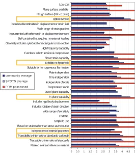
Traceable to international standards Traceability to international standards via length Independent of material properties Based on strain rather than stress as the output Simple to use Portable Wide range of sensitivity Includes rotation of strain direction Includes rigid body displacement In-plane capability Out-of-plane capability Temperature stable Independent of scale Time independent Rate independent Suitable for homogeneous illumination Exhibits no hysteresis Shear strain capability Functions in both tension & compression High frequency capability Geometry includes cylindrical or rectangular cross-section Self-contained i.e. requires no external loading Instrumented with other strain or displacement sensors Wide range of strain gradient Includes discontinuities in displacement or strain field Optical access Rough surface (RA > 0.5mm) Plane surface available Low cost
community average SPOTS average PRM possessed
0 0.5 1 1.5 2 2.5 3 3.5 4 4.5 5 Related to virtual reference material
Traceable to international standards Traceability to international standards via length Independent of material properties Based on strain rather than stress as the output Simple to use Portable Wide range of sensitivity Includes rotation of strain direction Includes rigid body displacement In-plane capability Out-of-plane capability Temperature stable Independent of scale Time independent Rate independent Suitable for homogeneous illumination Exhibits no hysteresis Shear strain capability Functions in both tension & compression High frequency capability Geometry includes cylindrical or rectangular cross-section Self-contained i.e. requires no external loading Instrumented with other strain or displacement sensors Wide range of strain gradient Includes discontinuities in displacement or strain field Optical access Rough surface (RA > 0.5mm) Plane surface available Low cost
community average SPOTS average PRM possessed
Fig. 1. Attributes and their weightings for the physical reference materials (PRM) together with the extent to which they are possessed by the selected PRM. The weightings (1 - unimportant, 2 - preferred,
3 - important, 4 - highly desirable, or 5 – essential) assigned by individual partners in the project were averaged and the same exercise repeated for the wider community including the SPOTS partners. Essential attributes were identified as those having an average weighting from the whole community greater than the mean plus a standard deviation of the weightings and are highlighted above. The extent
to which an attribute was possessed by the new PRM were assessed as 5 – completely possessed, 4 – to a large degree, 3 – to some degree, 2 – to a limited degree or in some circumstances, 1 – not possessed
2.2 Designing by adopting Rational Decisions
Acceptance by the community is a key component to the success of a standard and so the SPOTS project made significant efforts to involve the international community beyond the eleven partners from seven countries represented in the project. The basis for the design decisions was the rational decision making model [2] which involves the identification and weighting of attributes required in the design, the identification and evaluation of candidate designs and finally the embodiment of the selected design. The SPOTS partners initially brainstormed the attributes required in the reference material and the standardised test and then invited members of the Society for Experimental Mechanics and the participants in the 2003 Conference on Advances in Techniques in Experimental Mechanics to weight the attributes in terms of importance and to suggest additional attributes. This process resulted in 23 attributes which are shown in Figure 1 together with the weights assigned by the SPOTS partners and independently by the community.
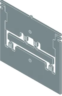
Fig. 2. Three-dimensional view of the physical reference material (EU Community Design Registration
000213467) which is scalable to any size and can be manufactured in any material. (©SPOTS consortium)
2.3 Physical Reference Material (PRM) design
Fig. 3 A physical standardised test material (EU Community Design Registration 000299094) manufactured from aluminium having a disc diameter of 50mm being tested using a ESPI system (Dantec Dynamics Q300)
with typical results shown inset. (© SPOTS consortium)
2.4 Standardised Test Material design
A similar approach was taken in designing the standardised test materials. The physical standardised test material is shown in Figure 3. The monolithic frame was incorporated again in order to provide reproducibility of the loading and boundary conditions. The gauge section or area of interest is the half of the disc making contact with the half plane and includes the area of the half-plane adjacent to the disc. Since this is a contact problem two pairs of thin cantilevers maintain the relative position of the two halves of the standardised test material. Loading in this case is only in compression as shown in the figure and can be quantified by measuring the relative motion of the two halves of the monolithic frame although traceability to a standard measure is not a requirement.
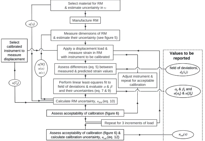
Fig. 4 Flow-chart for performing a calibration of an optical system for full-field strain measurement using the SPOTS reference material where u is uncertainty, W,a and c are characteristic dimensions, X is Poisson ratio andD and E are fit parameters relating to the correlation of the experimental and analytical strain distribution for the gauge section of the beam; the equations and figures referred to can be found in the SPOTS guidelines
[4]. (© SPOTS consortium) Manufacture RM
Measure dimensions of RM & estimate their uncertainty (see figure 5)
Apply a displacement load & measure strain in RM with instrument to be calibrated
Select material for RM & estimate uncertainty in X
Assess differences (eq. 5) between measured & predicted strain values
Perform linear least-squares fit to field of deviations & evaluate D&E
and their uncertainties (eq. 7 & 9) Dk&Ekand u(Dk) & u(Ek)
Calculate RM uncertainty, uRM(eq. 10)
Select calibrated instrument to
measure displacement
Assess acceptability of calibration (figure 6)
ucal(H)
field of deviations,
dk(i,j) u(X)
u(vk)
Values to be reported
Assess acceptability of calibration (figure 6) & calculate calibration uncertainty, ucal(eq. 12) u(W)
u(a) u(c)
Adjust instrument & repeat for acceptable
calibration
Repeat for 3 increments of load Manufacture RM
Measure dimensions of RM & estimate their uncertainty (see figure 5)
Apply a displacement load & measure strain in RM with instrument to be calibrated
Select material for RM & estimate uncertainty in X
Assess differences (eq. 5) between measured & predicted strain values
Perform linear least-squares fit to field of deviations & evaluate D&E
and their uncertainties (eq. 7 & 9) Dk&Ekand u(Dk) & u(Ek)
Calculate RM uncertainty, uRM(eq. 10)
Select calibrated instrument to
measure displacement
Assess acceptability of calibration (figure 6)
ucal(H)
field of deviations,
dk(i,j) u(X)
u(vk)
Values to be reported
Assess acceptability of calibration (figure 6) & calculate calibration uncertainty, ucal(eq. 12) u(W)
u(a) u(c)
Adjust instrument & repeat for acceptable
calibration
Repeat for 3 increments of load
3 Methodology
3.1 Calibration
The SPOTS project included the development and demonstration of a methodology for the use of the designs described above. The calibration procedure is described in detail in a set of guidelines published by the SPOTS project [4] and endorsed by VAMAS TWA26 [3] that includes the flowchart shown in Figure 4 in which the quantities to be reported as part of the calibration are highlighted in the box on the right. These include the uncertainties deduced for the calibration which will also be the minimum level of uncertainty in any future experiment conducted with the calibrated instrument or system. These uncertainties can be used to define confidence limits for the data obtained with the system as described by Patterson et al [5] and in more detail by Whelan et al [6] who performed a complete calibration of a commercially available electronic speckle pattern interferometer.
3.2 Evaluation
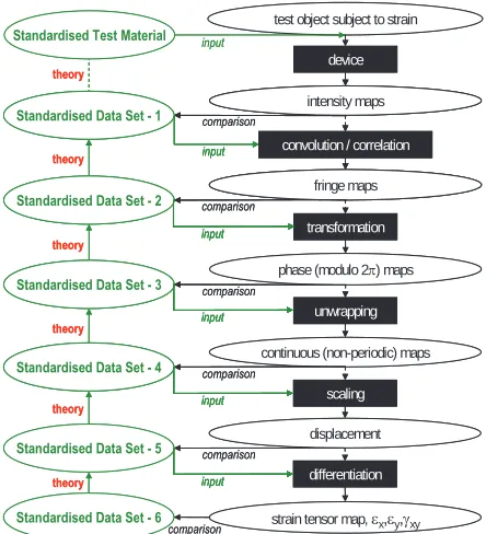
The omission of the requirement for traceability renders evaluation a potentially less exacting process. However the contact problem embodied in the physical standardised test material presents a number of significant challenges. This is entirely appropriate since the intention is to test the capabilities of the most sophisticated systems for full-field strain measurement. A round-robin within the SPOTS consortium has demonstrated that it is a challenge to generate a good set of data for both the half-plane and the disc [7]. The rigid body motion implicit in the design presents a major hurdle for many techniques, but can be significantly reduced by loading the standardised test material upside down as shown in Figure 3 rather than the other way up. Of course, such rigid body motion is not unusual in ‘real’ engineering situations where it is desired to measure deformation. As for the reference material a comprehensive set of guidelines for the use of the standardised test material were prepared by the SPOTS project [4] and endorsed by VAMAS TWA26 [3]. These guidelines include the capability to perform diagnostic tests by extracting data sets at various stages of the measurement and strain evaluation process and comparing them to standardised data sets as illustrated schematically in Figure 5. The standardised data sets are linked together by analytical expressions in a functional pathway which is defined in the guidelines for a wide range of techniques for optical strain measurement.
4 Discussion and Conclusions
The designs and protocols for the use of the reference material and standardised test material were embedded in a draft proposed standard [4] created by the SPOTS project, reviewed by an independent editor and endorsed for submission to ISO by the Technical Working Area 26 of VAMAS [3]. It is hoped that it will be published in the future as an ISO TTA (Technology Trends Assessment) prior to evolving into a full international standard. However, it is available for use at the moment and exemplars of its use have been published in the scientific literature [6, 7].
The standardised test material and protocol represent a challenging experiment for any laboratory to conduct successfully and will stretch the capabilities of the most skilled operators and most sophisticated instruments while at the same time allowing sub-system diagnostics so that weakness or shortcomings in the system under test can be identified. The standardised test material is a significant tool in establishing whether a system meets its design specification.
Fig. 5 Schematic illustrating the generic measurement process (right) for optical strain measurement systems and the relationship of the SPOTS standardized test and data sets (left) to the process. The ovals represent data
sets and the rectangles represent components of the strain measurement system. (© SPOTS consortium)
Acknowledgements
The authors cheerfully acknowledge the inputs of the following individuals in the SPOTS project: Daniel Albrecht, Philippe Brailly, MarieMarguerite Dugand, Erwin Hack, Jurgen Hofmann, Michel Honlet, Liam Kehoe, Malgozata Kujawinska, David Mendels, Qasim Saleem, Hans Reinhard Schubach, Leszek Salbut, Thorsten Siebert, Graham Sims, Carole Stochmil, Michel Taroni, Rachel Tomlinson, and Maurice Whelan. The SPOTS project was performed under an EC shared cost RTD contract, no. G6RD-CT-2002-00856 (SPOTS).
References
1. L.E. Schwer, Engineering with Computers, 23:245-252 (2007)
2. N. Cross, Engineering Design Methods (John Wiley & Sons, London, 1989) 3. www.twa26.org
4. www.opticalstrain.org
5. E.A. Patterson, E. Hack, P. Brailly, R.L. Burguete, Q. Saleem, T. Seibert, R.A. Tomlinson, M.P. Whelan, Optics and Lasers in Engineering, 45:550-564 (2007)
6. M.P. Whelan, D. Albrecht, E. Hack, E.A. Patterson, Strain, 44:180-190(2008)
7. E.A. Patterson, P. Brailly, R.L. Burguete, E. Hack, T. Siebert, M.P. Whelan, Strain, 43:167-180 (2007)
theory theory theory
transformation
phase (modulo 2S) maps test object subject to strain
Standardised Test Material
device
intensity maps
convolution / correlation
fringe maps
unwrapping
continuous (non-periodic) maps
Standardised Data Set - 2
Standardised Data Set - 3
scaling
displacement
strain tensor map, Hx,Hy,Jxy differentiation Standardised Data Set - 5
Standardised Data Set - 6 theory
theory
theory
Standardised Data Set - 4 Standardised Data Set - 1
input comparison comparison input input comparison input input input comparison comparison comparison theory theory theory transformation
phase (modulo 2S) maps test object subject to strain
Standardised Test Material
device
intensity maps intensity maps
convolution / correlation
fringe maps
convolution / correlation
fringe maps
unwrapping
continuous (non-periodic) maps
Standardised Data Set - 2 Standardised Data Set - 2
Standardised Data Set - 3 Standardised Data Set - 3
scaling
displacement
strain tensor map, Hx,Hy,Jxy differentiation Standardised Data Set - 5
Standardised Data Set - 6 theory
theory
theory
Standardised Data Set - 4 Standardised Data Set - 4 Standardised Data Set - 1 Standardised Data Set - 1