IJEDR1703159
International Journal of Engineering Development and Research (
www.ijedr.org
)
1127
Fully Stressed Design of Howe Truss using
STAAD.Pro Software
1Chandresh Kumar Jha, 2M.C. Paliwal,
1PG Scholar –Structural Engineering, 2Assistant Professor 1Department of Civil & Environmental Engineering,
1NITTTR, Bhopal, India
________________________________________________________________________________________________________
Abstract - This paper presents the study of optimization of Howe Truss by Fully Stressed Design (FSD) technique utilizing STAAD.Pro software version STAAD.Pro V8i (SELECT series4). Three span ranges of the trusses i.e. 8m, 10m and 12m have been considered and each truss has been subjected to 24 sorts of load cases by changing nodal load locations but load applied will always be symmetric. The four arrangements of load condition are taken, i.e., 100 kN, 125 kN, 150 kN and 175 kN. The total 72 number of trusses have been optimized in this study to achieve a target stress of 100 MPa. The optimal mass of all the trusses for each case and maximum deflection for each case have been calculated. Further deflection per unit mass have also been calculated and compared for each span with graph. Results of the study will be helpful in the designing of a truss that must fulfill the requirement of economy as well as strength.
Keywords: Howe Truss, STAAD, Fully Stressed Design, Optimization
________________________________________________________________________________________________________
I.INTRODUCTION
The resources are depleting day by day in present time and also the cost is increasing of material as well as labor cost is also increasing. As per the popular concept of present time in building construction i.e. the concept of green building we must conserve resources for the betterment of society in all aspect and for this the term optimal structure is widely used. Optimization of the structure can be done in various aspects which are known as objectives which could be weight, volume, cost or stiffness of the structure. By using optimization technique cost as well as material to be used in structure is saved. Optimality of the structure can be defined in terms of weight, volume, cost, stiffness etc. Some constraints are used for optimization. Some structures that lie within the constraints are generally known as feasible solutions to the optimization problem. These optimizations were supported (based on) size, shape and topology factors. So as to urge the truss optimized the cross sectional area of each member of truss are modified. It reduces the weight of structure and what is more the overall cost of the structure as well and hence Light weight structures are made instead of traditional heavy weight structures. Traditionally the structural optimization techniques includes; mathematical programming, optimality criteria, method of approximation and fully stressed design and fully utilized design.
Patrikar Avanti, Pathak K. K. (2016) has published a paper on Fully Stressed Design of Fink Truss using STAAD.Pro Software which is based on optimization technique of structures in this paper truss of three different spans has been considered with set of three loads and 27 different load cases. Result of the study may helpful in analysis and designing a truss that doesn’t waste material (1).Goel Shivam, Pathak K. K. (2016) presented a paper on the Optimization of Warren Truss using Topology Optimization in which 9 warren trusses have been considered with distinct span and height and each truss was subjected to 9 different loading conditions and 81 cases were formulated and each case was optimized to get a target stress of 100 MPa and Result of this study may be useful in the efficient utilization of the material and hence reducing the cost of the structure (2). David Greiner, Jose M. Emperador, Blas Galvan and Gabriel Winter (2015) published a paper on Comparing the Fully Stressed Design and Minimum Constrained weight Solutions in Truss Structures in which the optimization structural design problems of Fully Stressed Design (FSD) and Minimum Constrained Weight (MCW) are compared in a simple truss test case with discrete cross-section type bar sizing where both optimum designs are coincident (3).Ahrari A, Atai A. A. & Deb K. (2014) presented a paper on Simultaneous Topology, Shape and Size Optimization of Truss Structures by Fully Stressed Design based on Evolution Strategy (FSD-ES), and It has been also proved in this paper that fully stressed design is suitable method for optimal design of structure in which trusses are used and optimality is derived (4). C. Maraveas, A. Papagiannakis, K Miamis& K. Tasiouli(2014) presented a paper on Optimal Design of through-truss steel bridges which is based on shape and sizing optimal design for open-top through-truss steel bridges in this paper optimal design ( in terms of shape and sizing) of through steel bridges is performed in which several cases of simply supported bridges with different spans and varying width corresponding to different traffic lanes (i.e. 1 or 2 traffic lanes), were examined. The effect of three deck types which are reinforced concrete deck, fiber reinforced polymer deck and steel deck on the weight of the truss and the total weight had been investigated in which the least-weight shape and sizing optimal design was executed, with the height of the truss and cross-sectional area of its members constituting the design variables of the problem (5).
IJEDR1703159
International Journal of Engineering Development and Research (
www.ijedr.org
)
1128
II.FULLY STRESSED DESIGN
In this method it is assumed that each area carries a constant force, dependent only on the external load which means the internal force of one member is supposed not to affect the force in the other members. A re-sizing technique is used by assuming that Fi i.e. the internal force in the ith member, is constant and F
i can be expressed by stress (σi) times the cross-sectional area (Ai) and further this leads to the subsequent formulation and the formulas used in Fully Stressed Design are –
Fi = σi,new Ai,new = σi,old Ai,old --- (i) Ai, new = Ai, old σi, old / σi,o --- (ii)
This is an iterative technique and it is in huge practice nowadays. As our basic purpose is to maintain a same stress in each member of the truss after application of the load and we also know that stress is inversely proportional to area of cross section so if we reduce the area of cross section of any member, stress gets increase in the member and vice versa. So by increasing the area of cross section of any member, stress gets reduced and vice versa. After several iterations we can get same stress in all the member of truss as we required.
Stress = Force / Area --- (iii)
We take Howe truss of three different spans i.e. 8m, 10m and 12m with 2m height and analyzed them for 24 different load cases. In this way the total numbers of the trusses to be analyzed are 72.
III.STRUCTURAL MODELLING AND ANALYSIS
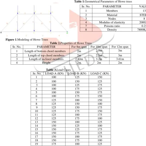
In our study we have taken 13 members Howe Truss having loads at all the joints as shown in figure 1. The loads at corner on upper chord are A and loads at centre of upper chord are B and loads acting on bottom chord are C. We have taken four sets of loads 100 ,125 ,150 ,175 and 3 positions that loads are acting at corners of upper chord(A) , loads acting at centre of upper chord (B) and loads acting on nodes of bottom chord of truss (C). Hence in this way by applying combinations we get 24 different Load Cases.
Table 1.Geometrical Parameters of Howe truss
Figure 1.Modeling of Howe Truss
Table 2.Properties of Howe Truss
Sr. No. PARAMETER For 8m span For 10m span For 12m span
1 Length of bottom chord members 2m 2.5m 3m
2 Length of top chord members 2m 2.5m 3m
3 Length of inclined members 2.83m 3.2m 3.61m
4 Height 2m 2m 2m
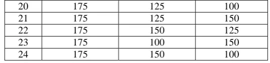
Table 3.Load Cases
Sr. No. PARAMETER VALUE
1 Members 13
2 Material STEEL
3 Nodes 8
4 Modulus of elasticity 200GPa
7 Poisons ratio 0.25
8 Density 7800Kg/m³
Sr. No. LOAD A (KN) LOAD B (KN) LOAD C (KN)
1 100 125 150
2 100 150 125
3 100 125 175
4 100 175 125
5 100 150 175
6 100 175 150
7 125 100 150
8 125 150 100
9 125 150 175
10 125 175 150
11 125 100 175
12 125 175 100
13 150 100 125
14 150 125 100
15 150 125 175
16 150 175 125
17 150 100 175
18 150 175 100
IJEDR1703159
International Journal of Engineering Development and Research (
www.ijedr.org
)
1129
IV.RESULTS AND DISCUSSION
FSD has been carried out in iterative manner to the target stress of 100 MPa and cross sectional areas of the members were noted down. Since the density of steel was known the steel i.e. 7800 kg/m3, mass of steel has been calculated for the overall truss structure. Circular section has been used for analysis in this study and diameter of each member each is considered to be different as per need. Optimal mass of the Howe trusses of three different spans i.e., 8m, 10m and 12m has been calculated for all 24 load cases and compared.
It has been observed that, the Optimal Maximum and Minimum Mass of Howe Truss of 8m span with 2m height are
Maximum Mass of truss = 1010.315 Kg at LOAD CASE 15
Minimum Mass of truss = 748.964 Kg at LOAD CASE 8
Hence Maximum and Minimum Mass occurs at Load Case 15 and Load Case 8 respectively.
Figure 2.Mass for Howe Truss of 8m span
It has been observed that, the Optimal Maximum and Minimum Mass of Howe Truss of 10m span and 2m height are
Maximum Mass of truss = 1395.957 Kg at LOAD CASE 15
Minimum Mass of truss = 1038.189 Kg at LOAD CASE 8
Hence Maximum and Minimum Mass occurs at Load Case 15 and Load Case 8 respectively.
Figure 3.Mass for Howe Truss of 10m span
It has been observed that, Optimal Maximum and Minimum Mass of Howe Truss of 12m span and 2m height are
Maximum Mass of truss = 1612.538 Kg at LOAD CASE 15
Minimum Mass of truss = 1200.649 Kg at LOAD CASE 8
Hence Maximum and Minimum Mass occurs at Load Case 15 and Load Case 8 respectively. 0
500 1000 1500
1 2 3 4 5 6 7 8 9 10 11 12 13 14 15 16 17 18 19 20 21 22 23 24
--Ma
ss
(k
g
)--->
---Load csaes--->
0 500 1000 1500
1 2 3 4 5 6 7 8 9 10 11 12 13 14 15 16 17 18 19 20 21 22 23 24
--Ma
ss
(k
g
)
-->
---
Load csaes---->
20 175 125 100
21 175 125 150
22 175 150 125
23 175 100 150
IJEDR1703159
International Journal of Engineering Development and Research (
www.ijedr.org
)
1130
Figure 4.Mass for Howe Truss of 12m span
And after finding optimal mass we calculate the maximum deflection of the trusses and it is observed that the maximum deflection of truss is
For 8m span = 9.949 mm occurs at central node of bottom of the truss. For 10m span = 13.275 mm occurs at central node of bottom of the truss. For 12m span = 17.322 mm occurs at central node of bottom of the truss.
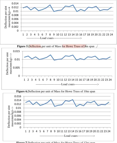
Then we have calculated the value of deflection per unit of mass for all spans and draw the graph for each span as below:
Figure 5.Deflection per unit of Mass for Howe Truss of 8m span
Figure 6.Deflection per unit of Mass for Howe Truss of 10m span
Figure 7.Deflection per unit of Mass for Howe Truss of 12m span
Comparison between the optimal mass of truss of three different spans for 24 load cases have been shown in the graph given below: 0 500 1000 1500 2000
1 2 3 4 5 6 7 8 9 10 11 12 13 14 15 16 17 18 19 20 21 22 23 24
----Ma ss (k g )- ---> ---Load csaes---> 0 0.002 0.004 0.006 0.008 0.01 0.012 0.014
1 2 3 4 5 6 7 8 9 10 11 12 13 14 15 16 17 18 19 20 21 22 23 24
Def lecti o n p er u in t m ass (m m /k g ) ---> ---Load csaes---> 0 0.005 0.01 0.015
1 2 3 4 5 6 7 8 9 10 11 12 13 14 15 16 17 18 19 20 21 22 23 24
Def lectio n p er u in t m ass (m m /k g )---> ---Load csaes---> 0 0.002 0.004 0.006 0.008 0.01 0.012 0.014 0.016
1 2 3 4 5 6 7 8 9 10 11 12 13 14 15 16 17 18 19 20 21 22 23 24
IJEDR1703159
International Journal of Engineering Development and Research (
www.ijedr.org
)
1131
Figure 8.Optimal Mass and load graph of truss showing comparison between mass of three different spans
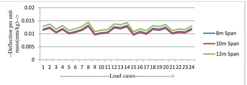
Comparison between the deflections per unit optimal mass of trusses of three different spans having 24 load cases have been shown in the graph given below:
Figure 9.Deflection per unit Mass and load graph of truss showing comparison between the three different spans
V.CONCLUSIONS
The following conclusions can be drawn from above Figure 8:
1. For 8m span Howe Truss having a rise of 2 m, it is observed that as the load cases are varied there is significant variation in the total steel mass of the truss. As the span is smaller than the other two spans, the overall comparison of steel mass is obviously less, but even with in the span there is some variation. As observed from the study the optimal mass for the load case 8 (i.e. 125/150/100) is 748.964 Kg and the same for the case 15 150/125/175 is 1010.315 kg , so there is significant variation in the steel mass.
2. For 10 m span Howe Truss having a rise of 2 m, it is seen that variation is more than 8m span in the steel mass. 3. For 12 m span Howe Truss having a rise of 2 m, it is seen that variation is more than 8m & 10m span in the steel mass. Since it is the biggest span in comparison to the other two, the overall steel mass will be more.
It is concluded that weight always increase with increase in the span or height. Hence, it is necessary for design engineer to optimize the structure to have the best height and span combination to save the material and make the structure economical. The following conclusions can be drawn out of the above graph in Figure 9:
1. The pattern of variation of graph for the deflection per unit of mass is same for all the three spans.
2. As the span increases the deflection per unit of also increases and the increment is rapidly growing with span.
REFERENCES
1. Fully Stressed Design of Fink Truss using STAAD.Pro Software. A. Patrikar, K. K. Pathak. 2016, Open Journal of Civil
Engineering, pp. 631-642.
2. Topology Optimization of Warren Trusses. Shivam Goel, K.K.Pathak. 2016, International Journal of Engineering Research,5,
pp. 95-98.
3. Comparing FSD & MCW . D G, J M Emerador, B G & G W. 2014.
4. Fully Stressed Design Evolution Strategy for Shape and Size Optimization of Truss Structures. Ahraria, A. and Atai, A.A.
2013, Computers and Structures, 123, pp. 58-67.
5. Optimal design of Truough-Truss Steel Bridge. C M, A. P., K. Miamis& K. Tasilauli. 2014, High Performance and Optimum
Design of Structures and Materials, pp. 465-476. 0
500 1000 1500 2000
1 2 3 4 5 6 7 8 9 10 11 12 13 14 15 16 17 18 19 20 21 22 23 24
---Ma
ss
(k
g
)-
-->
---Load cases--->
8m Sapn
10m span
12m Span
0 0.005 0.01 0.015 0.02
1 2 3 4 5 6 7 8 9 10 11 12 13 14 15 16 17 18 19 20 21 22 23 24
--Def
lectio
n
p
er
u
n
it
m
ass
(m
m
/k
g
)-->
---Load cases--->
8m Span
10m Span