IJEDR1703032
International Journal of Engineering Development and Research (www.ijedr.org)
213
Re-Engineering of Suspension Control Arm Using
Aluminum Alloy and Validation Using FEA
1
Benjamin Shiloh Davidson,
2Neelakrishnan S
1Assistant Professor, 2Professor 1Department of Automobile Engineering, 1PSG College of Technology, Coimbatore, India
________________________________________________________________________________________________________
Abstract— Aluminum alloys have high Strength to weight ratio. This feature of this metal has been a matter of study among
the engineers for the past few years. The recent manufacturing processes have solved the misery of manufacturing using aluminum alloys. This resulted in a strong eager for aluminum alloy application in all the fields of engineering. The development stages started in aerospace and aircrafts in earlier stages itself. The adaptation into road vehicle is a subject of study. The project here deals with application of aluminum alloy in Suspension components replacing steel with design change accompanying that can improve the material change aggressively.
Index Terms— FEA, Control Arm, Aluminum, Ansys.
________________________________________________________________________________________________________
I.INTRODUCTION (HEADING 1)
Transportation is a significant source of CO2 emissions with individual transportation (cars) producing a major share of it. Among
the many measures to reduce CO2 emissions from cars, technological ones (i.e. the ones that are intrinsic to the car and do not depend
on driver behavior) are the most reliable. Light weighting is one of the most effective and directly impacts CO2 emissions, as 100kg
saved on the mass of a car is equivalent to a reduction of 9 grams of CO2 per kilometer. With 2,700 kg/m3, the density of aluminum
is one third of that of steel. But such a weight reduction is seldom achieved since for a large number of parts, it is necessary to increase the average thickness of aluminum compared to steel to achieve the same part characteristics. It should be noted that, since the modulus of aluminum is lower than that of steel, the greater stiffness had to be achieved by improved geometry of the cast aluminum design. Each of the leading automakers are either investigating or actively increasing the aluminum content in their chassis and suspension systems. Thus the aim of this paper is re-engineering the suspension control arm using aluminum, make the design well suited along with the material change and thereby increasing the advantage of new lightweight aluminum material application and validation of this work with help of Finite Element Analysis tools.
II.OBJECTIVE &METHODOLOGY
The main objective involved is to reduce the un-sprung mass of the vehicle thereby obtaining better ride and stability by application of aluminum alloy. The weight reduction helps to solve the existing problem of increase in weight due to Global standards and Safety norms. The design change for alternative material to be used will help in bringing out the best out of it rather than slightly change in material alone.
Understanding Existing Materials
Selection of Existing Component
Modeling of Existing Component
Selection of New Material
IJEDR1703032
International Journal of Engineering Development and Research (www.ijedr.org)
214
Table 1: Process FlowIII.CAD MODELLING OF EXISTING COMPONENT
Measurements were taken using Vernier caliper and scale, noted down and based on that the modelling is done for individual parts and then assembled properly using CATIA (Computer Aided Three-Dimensional Interactive Application).
Figure 1: Modeling using CATIA Figure 2: Modelled Final Assembly
IV.FRONT AXLE LOAD CALCULATION
Thus for a deceleration Dx, the front axle load is given by:
---1
The specifications obtained from Users guide & journals gives following data:
W = 2600 Kg L = 2.425m c = 1.007m h = .6m g = 9.81m/s2
Wf =
1.007∗2600 2.425
+
.6∗2600∗.5
2.425∗9.81
= 1100Kg.
So, during braking from 60Km/hr to zero, calculating the load transfer and thereby obtaining the maximum front axle load, Wf
obtained as,
Wf = 1100 Kg.
Based on the calculations the maximum front axle load has been calculated and will be equally distributed between the two front wheels. So each wheel will be loaded half the front axle weight. So,
Load acting on the arm = Wf
2 = 550 Kg = 550*9.81
= 5395.5 N
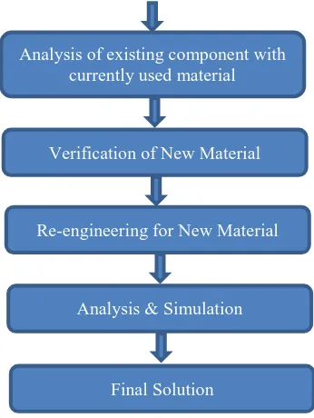
Analysis of existing component with currently used material
Verification of New Material
Re-engineering for New Material
Analysis & Simulation
IJEDR1703032
International Journal of Engineering Development and Research (www.ijedr.org)
215
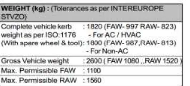
Table 2: Specification of Axle Load - TATA SUMO BSIIIThe specification data given in the TATA SUMO User’s manual also validated the fact that maximum possible load that can be acting on the front axle is 1100 Kg.
efore you begin to format your paper, first write and save the content as a separate text file. Keep your text and graphic files separate until after the text has been formatted and styled. Do not use hard tabs, and limit use of hard returns to only one return at the end of a paragraph. Do not add any kind of pagination anywhere in the paper. Do not number text heads—the template will do that for you.
Finally, complete content and organizational editing before formatting. Please take note of the following items when proofreading spelling and grammar.
V.MATERIAL IDENTIFICATION
The existing material with which the arm is made is unknown. To do the analysis using ANSYS, actual material is to be known. Optical Emission Spectrometer is used to find out the material composition at various parts (as in the figure at 1, 2 & 3).
Figure 3: Material tested zones (1, 2, & 3)
Optical Emission Spectrometry (OES) technique utilizes a high-energy spark created across an argon-filled gap between an electrode and a sample of the material to be analyzed. The spark creates an emission of radiation from the excited sample surface with wavelengths characteristic of the elemental composition.
Figure 4: Principle of working of Optical Emission Spectrometry
The spectrum of radiation is separated into the distinct element lines and the intensity of each line is measured. Finally, these are precisely converted into concentration values for each element present. Typical applications involve determination of the alloying content of iron and steel, aluminum, copper, nickel, zinc, lead and many other metals and alloys. Optical Emission Spectrometry continues to be the reference technique for direct chemical analysis of solid metallic samples. Based on the spectrometry study we got the materials as:
Forged part - ST 25 (at 1 & 2) Fabricated part - SAE 1005 (at 3)
VI.SIMULATION
IJEDR1703032
International Journal of Engineering Development and Research (www.ijedr.org)
216
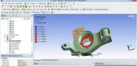
Figure 5: Loading on Lower Control Arm Figure 6: Application of boundary condition and LoadAnalysis on Existing Design for SAE 1005 & ST 25
Material Properties ST 25
SAE 1005
Parameters
Analysis on Existing Design for SAE 1005 & ST 25
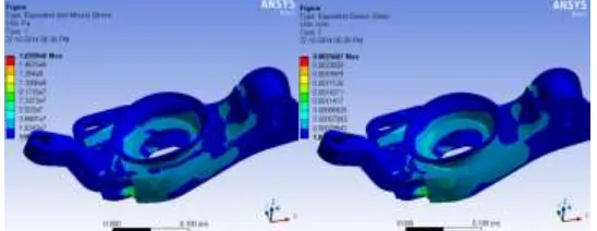
Figure 7: Von-Mises analysis for SAE 1005 & ST 25
Analysis on Existing Design with aluminum 6061 PH
IJEDR1703032
International Journal of Engineering Development and Research (www.ijedr.org)
217
Analysis on Existing Design with aluminum 6061 PHFigure 8: Von-Mises analysis for aluminum 6061 PH
Analysis on Existing Design with combination of aluminum 6061 PH & ST 25
Material Properties ALUMINIUM 6061 PH
ST 25
Parameters
Analysis Existing Design with combination of aluminum 6061 PH & ST 25
IJEDR1703032
International Journal of Engineering Development and Research (www.ijedr.org)
218
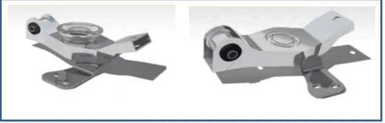
VII.PROPOSED DESIGN EVOLUTIONA material change won’t provide the complete advantage unless until a design change is provided [1]. So, in order to validate the effect, proposed design was done without effecting the assembly, keeping all constrains and parameters of the total wheel and axle assembly the same and modifying only on the sub-assembly.
Figure 10: New designed Assembly with & without mounting cap for spring
The proposed design here above consists of the old solid arm eliminated and integrated to the single arm body. The cup in which the spring is mounted is retained in this case and the design is done so with thickness as 4mm for the part. This design in which the cup for mounting the spring has been eliminated and is integrated to the arm body itself. This results in reduced cross section while maintaining the functionality un-affected.
VIII.PROPOSED DESIGN SIMULATION
The analysis is done with all the constraints and forces applied same as done for existing one. The material for arm is given aluminum 6061 PH and others the standard materials. The meshing is done and analysis is carried out. The results are published as below.
Analysis on Proposed Design-1 with aluminum 6061 PH
Materials Properties ALUMINIUM 6061 PH
ST 25
IJEDR1703032
International Journal of Engineering Development and Research (www.ijedr.org)
219
Figure 11: Von-Mises analysis for aluminum 6061 PH
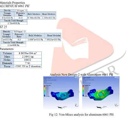
Analysis on Proposed Design-2 with aluminum 6061 PH
Materials Properties ALUMINIUM 6061 PH
ST 25
Parameters
Analysis New Design-2 with Aluminium 6061 PH
IJEDR1703032
International Journal of Engineering Development and Research (www.ijedr.org)
220
IX.CONCLUSION
Figure 13: Comparison of Analysis Results for Various Designs
Based on the Ansys study for static conditions, we came across that with cup assembly has stress level and elastic strain the lowest. But when compared with the major factor the weight of the assembly and the stress and strain level corresponding, 2nd design (without cap) is much more acceptable and easy to manufacture. The graph plotted above compares all the 5 designs done. It clearly depicts how the new design along with the material change is favorable.
X.REFERENCES
[1] Lightening Approach for Small Vehicles by Developing Extruded Aluminum Suspension Arm by Yotsuya, G. and Yamauchi, R, SAE Int. J. Mater. Manf.6(1):124-130, 2013, doi:10.4271/2012-32-0094.
[2] Finite Element Analysis and Topology Optimization of Lower Arm of Double Wishbone Suspension using RADIOSS and Optistruct by Vinayak Kulkarni, Anil Jadhav, P. Basker, International Journal of Science and Research (IJSR) ISSN (Online): 2319-7064, pp 639-643
[3] Borns, R. and Whitacre, D., "Optimizing Designs of Aluminum Suspension Components Using an Integrated Approach," SAE Technical Paper 2005-01-1387, 2005, doi:10.4271/2005-01-1387
[4] Design and Optimization of Sheet Metal Control Arm for Independent Suspension System by P. Nagarjuna & K. Devaki Devi, International Journal of Engineering Research and Applications (IJERA) ISSN: 2248-9622 www.ijera.comVol. 2, Issue5, September-October 2012, pp.535-539
[5] Wrought Aluminium Technologies for Automobiles by Takashi INABA, Kenji TOKUDA, Hiroyuki YAMASHITA, Yoshiki TAKEBAYASHI, Dr. Tadayuki MINOURA, Seiji SASAB, Takashi INABA, Kenji TOKUDA, Aluminum Sheets & Coils Research Department, Moka Plant, Aluminum & Copper Company, KOBELCO TECHNOLOGY REVIEW NO. 26 DEC. 2005
[6] Methods for Measuring Vertical Tire Stiffness by R. K. Taylor, L. L. Bashford, M. D. Schrock, Transactions of the ASAE, VOL. 43(6): 1415-1419, American Society of Agricultural Engineers 0001-2351 / 00 / 4306-1415
[7] Prof. Dipl.-Ing. Jörnsen Reimpell, Dipl.-Ing. Helmut Stoll, Prof. Dr.-Ing. Jürgen W. Betzler, “The Automotive Chassis: Engineering principles,” second edition, Butterworth-Heinemann publication.
[8] Li-Hui Zhao, Song-Lin Zheng, Jin-Zhi Feng, “Failure mode analysis of torsion beam rear suspension under service conditions” Science Direct, Engineering Failure Analysis 36 (2014) 39–48.
[9] Vivek Zolekar, Dr. L.N. Wankhade, “Finite Element Analysis and Optimization of I.C. Engine Piston Using RADIOSS and OptiStruct,” Altair technology conference,2013.
[10] Engineering Materials - An Introduction to Microstructures, Processing and Design by Michael F. Ashby and David R. H. Jones, Butterworth-Heinemann, 2006.
[11] Fundamentals of Materials Science and Engineering by William D. Callister, Jr., Wiley, 2011 [12] Handbook of Materials Selection by Myer Kutz, John Wiley & Sons, 2002
[13] Materials for Automobile Bodies by Geoff Davies
[14] Materials Selection in Mechanical Design by Michael F. Ashby