ADVANCED ERROR RECOVERY FOR TMR
SYSTEMS
Anjana Suresh
1, Sabi S.
21
Student, Dept. Of ECE, Sree Buddha College Of Engineering, Alappuzha,( India)
2
Asst. Professor,Dept. of ECE, Sree Buddha College of Engineering, Alappuzha,(India)
ABSTRACT
The embedded systems are widely used in safety critical applications like process control in industries, avionics
in space explorations and in medical field for patient life support monitoring etc. It should be equipped with
appropriate error recovery techniques, as any type of faults in the system are in tolerable. We had modified the
existing system for improved performance and less area overhead. We reused the scan-chain flip-flops
fabricated for testability purposes to detect and correct faulty modules in the presence of single or multiple
transient faults. The manifested errors were detected at the modules’ outputs, while the latent faults were
detected by comparing the internal states of the TMR modules. Upon detection of any mismatch, the faulty
modules were located and the state of a fault-free module was copied into the faulty modules. We implemented
the same with a single mode of operation. Only a single circuitry was used for comparing the states and
recovering erroneous modules. Thus, the VHDL code for the system was developed and implemented in Spartan
3E XC3S100e TQ144 FPGA board.
Keywords:
Roll-Forward Error Recovery, Scan Chain, Triple Modular Redundancy (Tmr), FPGA.I. INTRODUCTION
Embedded processors should be equipped with error detection and correction mechanisms as they are widely
used in safety critical applications. Performance is another important issue in these applications as most of them
have real-time constraints. Constraints include both timing constraints and fault tolerance requirements. Thus the
system should be provided with fault tolerant technique without violating the timing constraints. Sometimes the
system may fail or give incorrect outputs. Both should not occur in case of safety critical applications or hard real
time systems. To address these, TMR systems are introduced.
Triple Module Redundancy (TMR), first proposed by Von Neumann, is one such technique where a module is
replicated three times and the output extracted from a majority voter. Triple modular redundancy, sometimes
called triple-mode redundancy, (TMR) is a fault-tolerant form of N modular redundancy, in which three systems
perform a process and that result is processed by a majority-voting system to produce a single output. If any one
of the three system fails, the other two systems can produce correct output and thus mask the fault. Some Error
Correction Code memory uses triple modular redundancy hardware rather than the common Hamming code,
because triple modular redundancy hardware is faster than Hamming error correction hardware. Safety critical
(i.e., increase in board space and system payload) as the base design is implemented thrice. The hardened design
has 200% more area than the original circuit.
A major shortcoming of the traditional TMR is its inability to cope with TMR failures. TMR failure refers to a
failure in a TMR system caused by multiple faulty modules or a faulty voter. TMR system can withstand only
single upset at any instant of time, thus, if two redundant modules are simultaneously upset, then the output
cannot be guaranteed to be correct. Also, if two modules are permanently damaged, the whole TMR system has
to be discarded. The redundant system is considered SEU tolerant under the assumption that the voter circuit is
completely immune to SEUs [11].
All these shortcommings can be addressed if the TMR system is provided with an additional controller. The
controller should act as the brain of the entire system. If it could detect the faulty module and recover the same,
then it will be a great success. ScTMR is a modified form of TMR system with a controller which can detect and
recover a single faulty module[8]. This system is extended to detect and recover multiple faulty modules and
named SMERTMR[10]. If SMERTMR is further modified to reduce the area used and with low power
consumption, then it will become an advanced error recovery technique. So the “Advanced Error Recovery for
TMR systems” was proposed.
II. ERROR RECOVERY MECHANISMS
Real-time computing systems often have stringent reliability and performance requirements. Failures in
real-time systems can result in data corruption and lower performance, leading to catastrophic failures. Detection
of the fault and its recovery in TMR systems is the main aim of this work. Even though TMR is considered
one of the best faults tolerant techniques, it suffers from TMR failures. The probability of failure of the system
due to two faulty modules is more common than a faulty voter. Two independent faults can arrive at two
different modules, which results in the failure of the system. The adverse effects of absence of error recovery
techniques in TMR cannot be tolerated in safety critical applications. So the need of appropriate error recovery
technique is of atmost importance. When a transient error occurs in a computing system, data recovery is
needed to continue system operation.
After detecting the faulty module, appropriate error recovery technique should be applied to recover the
error successfully. Also the error detected in a single module should be over written, otherwise the fault will
accumulate and chances for TMR failure will increase. All error recovery techniques first detect the error and
then recover the system. Most recovery techniques use the state of the fault-free module for restoring the
faulty system. Transient error recovery is achieved by restoring correct states to continue operation.
2.1 Check point
All processes save their local states at certain instants of time. A local check point is a snapshot of the state of
the process at a given instance. Checkpoints are devised under the assumption that, a process stores all local
checkpoints on the stable storage and also the process is able to roll back to any of its existing local
2.2 Retry mechanism
Normally, an error recovery technique restores the state of the system to a fault free state once an error is
detected. A majority of previous error recovery techniques in TMR systems exploit retry mechanism. In a
retry mechanism, once an error is detected, the faulty module will re-execute the entire process. Retry
techniques are not suitable for tight deadline applications as they impose significant performance overhead to
the system.
2.3 Rollback recovery
Another way to restore correct states is through re-computation, which is called rollback recovery. In rollback
recovery, system operation is backed up to some point in its processing, which is called a checkpoint. When an
error occurs and is detected during operation, the system will restore its state back to previous checkpoint and
re-compute. Re-computation has been used in TMR systems for recovery. However, re-computation has time
overhead.
2.4 Rollforward recovery
Check-pointing and re-computation impose significant performance overhead which may violate the real-time
requirements of safety-critical applications. In contrast, roll forward recovery mechanisms are efficient to be
used in tight deadline applications as they do not rely on re-computation. In roll forward error recovery
technique whenever an error is found in one of the module’s output, then itself the correct data is re-written to
the faulty one.
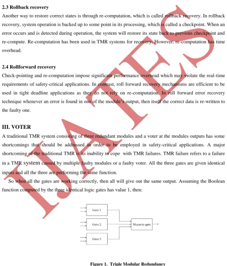
III. VOTER
A traditional TMR system consisting of three redundant modules and a voter at the modules outputs has some
shortcomings that should be addressed in order to be employed in safety-critical applications. A major
shortcoming of the traditional TMR is its inability to cope with TMR failures. TMR failure refers to a failure
in a TMR
system
caused by multiple faulty modules or a faulty voter. All the three gates are given identicalinputs and all the three are performing the same function.
So when all the gates are working correctly, then all will give out the same output. Assuming the Boolean
function computed by the three identical logic gates has value 1, then:
(a) If no circuit has failed, all three circuits produce an output of value 1, and the majority gate output is 1.
(b) If one circuit fails and produces an output of 0, while the other two are working correctly and produce an
output of 1, the majority gate output is 1, i.e., it still has the correct value.
And similarly for the case when the boolean function computed by the three identical circuits has value 0.
Thus, the majority gate output is correct as long as two of the three identical logic circuits are working
correctly. The majority gate is a simple AND–OR circuit. If the inputs to the majority gate are denoted by x, y
and z, then the output of the majority gate will be xy + yz + xz. Thus, the majority gate is the carry output of a
full adder, i.e., the majority gate is a voting machine.
3.1 Importance of voter
In TMR, base design is implemented in three modules. All the modules are doing the same operation. Outputs
from all the modules are given to voter. Voter selects the correct output even though one moduleis faulty. An
error signal is send to the controller which initiates comparison and recovery operation. Check point signals
are activated at definite points.
The traditional voter will route the correct module output as the ultimate output though one of the module
output fails. However, it cannot route the correct module output as the ultimate output in case of multiple
faulty modules. So, in the new voter proposed error signals will be generated in case of difference between the
module outputs. These error signals will trigger the controller to correct the module outputs and thus produce
accurate output. In TMR, three identical logic circuits (logic gates) are used to compute the same set of
specified Boolean function.
If there are no circuit failures, the outputs of the three circuits are identical. But due to circuit failures, the
outputs of the three circuits may be different. A majority gate is used to decide which of the circuits’ outputs is
the correct. The majority gate output is 1 if two or more of the inputs of the majority gate are 1; output is 0 if
two or more of the majority gate’s inputs are 0.
The majority gate is a simple AND–OR circuit: if the inputs to the majority gate are denoted by x, y and z,
then the output of the majority gate is xy + yz + xz. The traditional voter will route the correct module output
as the ultimate output though one of the module output fails. However, it cannot route the correct module
output as the ultimate output in case of multiple faulty modules.
Traditional TMR voter masks the faults affecting only one module. In addition, the faulty module cannot be
recovered in a traditional TMR system, as the system cannot identify the faulty module. The proposed
technique use modified voters to diagnose the faulty module. The voters presented in some cases are hardware
based, while the technique proposed in some cases uses a software based method for voting and fault
diagnosis resulting in negative impact on the system performance. Some of these voters keep the history of
faulty modules and, whenever the number of consecutive recovery operations caused by one module exceeds a
predefined number, the error is then identified as a permanent error.
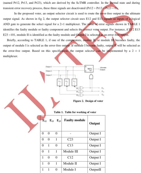
3.2 Proposed Voter
In a TMR system, detection and correction of a faulty module is a challenging issue and is still an ongoing
research topic. In particular, a wrong detection or inability to locate the faulty module can significantly affect
the system reliability. To address this issue, a voter that can identify the faulty module is presented.
voter can be used in both ScTMR and SMERTMR techniques. The architecture of the proposed voter is
depicted in fig 2. As shown in the figure, three comparators (C12, C13, and C23) are used to represent any
mismatch between TMR modules. As an example, E23 signal is activated once a mismatch between Outputs II
and III is detected. If one of the modules generates an erroneous output (e.g., Output I), two of the
comparators (here, C12 and C13) will activate the mismatch signals (here, E12 andE13) and only one of the
comparators (here, C23) will not activate the corresponding mismatch signal (here, E23). In case of a faulty
comparator (e.g., C13), only the corresponding signal (here, E13) is activated and the other signals (here, E12
and E23) are deactivated. In order to detect permanent faults, the proposed voter employs three input signals
(named Pr12, Pr13, and Pr23), which are derived by the ScTMR controller. In the normal state and during
transient error recovery process, these three signals are deactivated (Pr12 = Pr13 = Pr23 = 0).
In the proposed voter, an output selector circuit is used to route the error-free output to the ultimate
output signal. As shown in fig 2, the output selector circuit uses E12 and E13 signals as inputs of a logical
AND gate to generate the select signal for a 2×1 multiplexer. The value of error signals shown in TABLE 1
identifies the faulty module or faulty component and selects the correct voter output. For instance, if E12 E13
E23 =101, module II is identified as the faulty module and Output I is selected as an error-free output.
Briefly, according to TABLE 1, if one of the comparators, module II, or module III becomes faulty, the
output of module I is selected as the error-free output. If module I become faulty, output II will be selected as
the error-free output. Based on this specification, the output selector can be implemented by a 2 × 1
multiplexer.
Figure 2. Design of voter
Table 1. Table for working of voter
Faulty module
Faulty module
Output
0 0 0
-
Output I
0 0 1
C23
Output I
0 1 0
C13
Output I
0 1 1
Module III
Output I
1 0 0
C12
Output I
1 0 1
Module II
Output I
1 1 0
Module I
OutputII
1 1 1
Unrecoverable
X
In the new voter proposed error signals will be generated in case of difference between the module
outputs. These error signals will trigger the controller to correct the module outputs and thus produce accurate
output
.
IV. ScTMR
TMR is an important and widely used fault tolerant technique. It can select the correct output in the presence
of a faulty module, but unable to detect and correct the faulty module. Also it fails if multiple modules are
faulty and if the voter is faulty. If an error occurred in a module is not corrected, then in the next cycle of
operation another module may become faulty and thus it leads to the problem of multiple faulty modules. So
the accumulation of errors should be avoided in order to make the system more reliable.
On the detection of an error, the system should be able to first detect the error on its occurrence and then
recover it in the same cycle of operation without giving a chance for the system to carry the errors to the next
cycle of operation. All error recovery techniques should have the ability to rewrite the faulty module with the
state of fault free module on the detection of any error.
To address the issue of transient error, an error recovery technique should be employed along with the
TMR technique. That is the TMR is modified to include a controller, which is the brain of the system. The
working of controller determines the actions of the system and its efficiency. The first error recovery system
for TMR to include a controller is the ScTMR or Scan chain based error recovery system for TMR systems.
The error recovery technique used is roll forward error recovery technique. The system reuses the scan chains
which are implemented in the VLSI circuits to detect the fabrication defects. Scan chain is a cost-effective
technique used in Design for Testability (DFT) to provide a simple way for testing combinational and
sequential circuits. The same is used here for the recovery of the fault free state from the faulty state. Once a
transient error is detected, the state of one of the fault-free modules is copied to the faulty module using the
scan chains.
4.1 State Diagram
The ScTMR architecture consists of three redundant modules, a voter and a ScTMR controller. The voter
detects errors and reports them to the ScTMR controller. The ScTMR controller detects the error and employs
an appropriate mechanism to remove the errors from the system. The ScTMR controller then uses scan chains
to copy the state of a fault-free module into the faulty module. The scan chain signals including Scan Chain
Input (SCI), Scan Chain Output (SCO), and Scan Chain Enable (SCE) are controlled by the ScTMR controller.
4.2 ScTMR Controller
Controller is responsible for all the actions that account for the detection operation of system. After getting the
error signal from the voter, the controller initiate its action of recovery. The controller is used for recovery of
both transient and permanent fault recovery. Upon activation of the error signal, the ScTMR controller
switches from the
normal operation to the recovery mode to restore the state of the faulty module using the state of one of the
fault-free modules.
In the recovery mode, the internal states of the two fault free modules are shifted out using the scan chains
signal of the fault free modules is connected to the SCO signal of the same module. Also the SCI signal of the
faulty module is connected to the SCO signal of one of the fault free modules. Using this configuration, the
state of one of the fault free modules will be copied into the faulty module after Lsc clock cycles.
4.3 Disadvantages
Although ScTMR reduces the probability of TMR failures, it suffers from two major shortcomings. First,
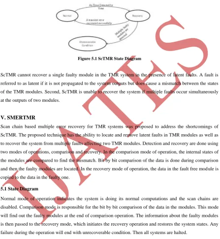
Figure 5.1 ScTMR State Diagram
ScTMR cannot recover a single faulty module in the TMR system in the presence of latent faults. A fault is
referred to as latent if it is not propagated to the system outputs but does cause a mismatch between the states
of the TMR modules. Second, ScTMR is unable to recover the system if multiple faults occur simultaneously
at the outputs of two modules.
V. SMERTMR
Scan chain based multiple error recovery for TMR systems was proposed to address the shortcomings of
ScTMR. The proposed technique has the ability to locate and remove latent faults in TMR modules as well as
to recover the system from multiple faults affecting two TMR modules. Detection and recovery are done using
two modes of operations, comparison and recovery. In the comparison mode of operation, the internal states of
the modules are compared to find the mismatch. Bit by bit comparison of the data is done during comparison
and then the faulty modules are located. In the recovery mode of operation, the data in the fault free module is
copied to the data in the faulty one.
5.1 State Diagram
Normal mode of operation indicates the system is doing its normal computations and the scan chains are
disabled. Comparison mode is responsible for the bit by bit comparison of the data in the modules. This mode
will find out the faulty modules at the end of comparison operation. The information about the faulty modules
is then passed to the recovery mode, which initiates the recovery operation and restores the system states. Any
failure during the operation will end with unrecoverable condition. Then all systems are halted.
Initially the system is in the normal mode of operation. When an error is detected by the voter or when a
check point signal is activated, the system switches to comparison mode of operation. After comparison, if no
system is found faulty, then the control will go to the normal mode. If it fails to detect the fault, then it will go
to the unrecoverable state. If one or two erroneous modules are detected, then the recovery mode of operation
to unrecoverable state. If all the modules are faulty, then also the system goes into the unrecoverable
condition.
5.2 Comparison Mode
In this mode, the SMERTMR controller enables the scan chains of the SMERTMR modules. The internal
states of the modules are scanned out through the SCO pin of the scan chain flip flops. Each of the bits is
compared using XOR gates connected to the outputs of each pair of modules. At the end of comparison
process, the faulty module is located.
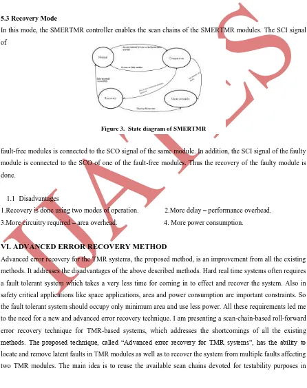
5.3 Recovery Mode
In this mode, the SMERTMR controller enables the scan chains of the SMERTMR modules. The SCI signal
of
Figure 3. State diagram of SMERTMR
fault-free modules is connected to the SCO signal of the same module. In addition, the SCI signal of the faulty
module is connected to the SCO of one of the fault-free modules. Thus the recovery of the faulty module is
done.
1.1 Disadvantages
1.Recovery is done using two modes of operation. 2.More delay – performance overhead.
3.More circuitry required – area overhead. 4. More power consumption.
VI. ADVANCED ERROR RECOVERY METHOD
Advanced error recovery for the TMR systems, the proposed method, is an improvement from all the existing
methods. It addresses the disadvantages of the above described methods. Hard real time systems often requires
a fault tolerant system which takes a very less time for coming in to effect and recover the system. Also in
safety critical applications like space applications, area and power consumption are important constraints. So
the fault tolerant system should occupy only minimum area and use less power. All these requirements led me
to the need for a new and advanced error recovery technique. I am presenting a scan-chain-based roll-forward
error recovery technique for TMR-based systems, which addresses the shortcomings of all the existing
methods. The proposed technique, called “Advanced error recovery for TMR systems”, has the ability to locate and remove latent faults in TMR modules as well as to recover the system from multiple faults affecting
order to compare the internal states of TMR modules to locate and restore the correct state of faulty modules
using the state of non-faulty modules.
The proposed system can detect the error that occurs in a triple modular redundant system and to recover
the same using minimum circuitry and less time. The system also aims to deal with the condition of multiple
faults arriving at multiple modules. The system is actually a TMR system with an additional controller. The
controller is the brain of the system. It is responsible for both error detection and recovery.
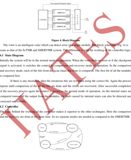
Figure 4. Block Diagram
The voter is an intelligent voter which can detect error of a single module. The block schematic (fig. 4) is
same as that of the ScTMR and SMERTMR system. The difference is with the working of the controller logic.
6.1 State Diagram
Initially the system will be in the normal mode of operation. When the voter finds an error or if the checkpoint
signal is activated, it switches the control to comparison and recovery mode of operation. In the comparison
and recovery mode, each of the bits from the scan chain flip flops is compared. The first bit of all the modules
is compared first.
If there is any mismatch, then the erroneous bits are rewritten using the correct bit. Again the process
repeats until comparison of the all the bits are done and the errors are recovered. After successful completion
of the recovery process again the control is passed to the normal mode of operation. As the internal states are
compared instead of the output from the modules, the fault caused by internal states can also be detected and
corrected successfully.
6.2 Controller
The logic behind the working of the controller makes it superior to the other techniques. Here the comparison
and the recovery are done at the same time. So no separate modes are needed as compared to the SMERTMR.
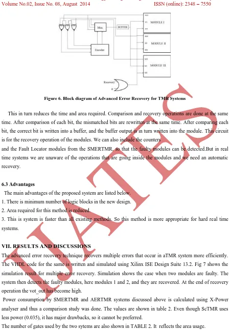
Figure 6. Block diagram of Advanced Error Recovery for TMR Systems
This in turn reduces the time and area required. Comparison and recovery operations are done at the same
time. After comparison of each bit, the mismatched bits are rewritten at the same time. After comparing each
bit, the correct bit is written into a buffer, and the buffer output is in turn written into the module. This circuit
is for the recovery operation of the modules. We can also include the counters
and the Fault Locator modules from the SMERTMR, so that the faulty modules can be detected.But in real
time systems we are unaware of the operations that are going inside the modules and we need an automatic
recovery.
6.3 Advantages
The main advantages of the proposed system are listed below.
1. There is minimum number of logic blocks in the new design.
2. Area required for this method is reduced.
3. This is system is faster than all existing methods. So this method is more appropriate for hard real time
systems.
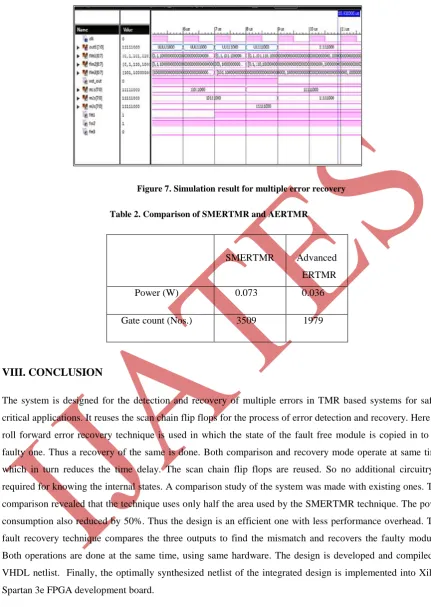
VII. RESULTS AND DISCUSSIONS
The advanced error recovery technique recovers multiple errors that occur in aTMR system more efficiently.
The VHDL code for the same is written and simulated using Xilinx ISE Design Suite 13.2. Fig 7 shows the
simulation result for multiple error recovery. Simulation shows the case when two modules are faulty. The
system then detects the faulty modules, here modules 1 and 2, and they are recovered. At the end of recovery
operation the vot_out has become high.
Power consumption by SMERTMR and AERTMR systems discussed above is calculated using X-Power
analyser and thus a comparison study was done. The values are shown in table 2. Even though ScTMR uses
less power (0.035), it has major drawbacks, so it cannot be preferred.
Figure 7. Simulation result for multiple error recovery
Table 2. Comparison of SMERTMR and AERTMR
SMERTMR Advanced
ERTMR
Power (W) 0.073 0.036
Gate count (Nos.) 3509 1979
VIII. CONCLUSION
The system is designed for the detection and recovery of multiple errors in TMR based systems for safety
critical applications. It reuses the scan chain flip flops for the process of error detection and recovery. Here the
roll forward error recovery technique is used in which the state of the fault free module is copied in to the
faulty one. Thus a recovery of the same is done. Both comparison and recovery mode operate at same time,
which in turn reduces the time delay. The scan chain flip flops are reused. So no additional circuitry is
required for knowing the internal states. A comparison study of the system was made with existing ones. This
comparison revealed that the technique uses only half the area used by the SMERTMR technique. The power
consumption also reduced by 50%. Thus the design is an efficient one with less performance overhead. This
fault recovery technique compares the three outputs to find the mismatch and recovers the faulty modules.
Both operations are done at the same time, using same hardware. The design is developed and compiled to
VHDL netlist. Finally, the optimally synthesized netlist of the integrated design is implemented into Xilinx
Spartan 3e FPGA development board.
REFERENCES
[1] S. Yu and E. J. McCluskey, “On-line testing and recovery in TMR systems for real-time applications,” in
[2] H. Kim and K. G. Shin, “Design and analysis of an optimal instruction retry policy for TMR controller computers,” IEEE Trans. Comput., vol. 45, no. 11, pp. 1217–1225, Nov. 1996.
[3] P. K. Samudrala, J. Ramos, and S. Katkoori, “Selective triple modular redundancy (STMR) based single-event upset (SEU) tolerant synthesis for FPGAs,” IEEE Trans. Nucl. Sci., vol. 51, no. 5, pp. 2957–2969,
Oct. 2004.
[4] P. K. Chande, A. K. Ramani, and P. C. Sharma, “Modular TMR multiprocessor system,” IEEE Trans. Ind. Electron., vol. 36, no. 1, pp.34–41, Feb. 1989.
[5] F. L. Kastensmidt, L. Sterpone, L. Carro, and M. S. Reorda, “On the optimal design of triple modular
redundancy logic for SRAM-based FPGAs,” in Proc. Design Autom. Test Eur. Conf. Exhibit., 2005,
pp.1530–1591.
[6] X. Wang, “Partitioning triple modular redundancy for single event upset mitigation in FPGA,” in Proc.
Int. Conf. E-Product E-Service EEntertain., 2010, pp. 1–4.
[7] S. Nomura, M. D.Sinclair, C.-H. Ho, V.Govindaraju, M. de Kruijf and K. Sankaralingam, “Sampling +
DMR: Practical and low-overhead permanent fault detection,” in Proc. 38th Int. Symp. Comput. Arch.,
2011,pp. 201–212.
[8] M. Ebrahimi, S. G. Miremadi, and H. Asadi, “ScTMR: A scan chain based error recovery technique for
TMR systems in safety-critical applications,” in Proc. Design Autom. Test Eur. Conf. Exhibit., 2011, pp.
1–4.
[9] Norbert Seifert et.al., “Sequential Element Design With Built-In Soft Error Resilience,” IEEE Transactions
On Very Large Scale Integration (VLSI) Systems, Vol. 14, No. 12, December 2006, pp.1368-1378.
[10] Seyed Ghassem Miremadi, Mojtaba Ebrahimi, “Low-Cost Scan-Chain-Based Technique to Recover
Multiple Errors in TMR Systems”, IEEE Transactions On Very Large Scale Integration (VLSI) Systems,
Vol. 21, No. 8, August 2013, pp 1454-1468.