E-ISSN 2308-9830 (Online) / ISSN 2410-0595 (Print)
MPLS Recovery Schemes: An Experimental Evaluation
Seema Anand Ladhe1 and Vijay T Raisinghani2
1, 2
School of Engineering, NMIMS University, Mumbai, India
E-mail: [email protected], [email protected]
ABSTRACT
Multiprotocol Label Switching (MPLS) is widely used in large Internet backbone because of its traffic engineering capabilities. One of the key features of MPLS Traffic Engineering (MPLS-TE) is fast recovery in case of failure of link or node. MPLS-TE is mainly used to improve network survivability and quality of service (QoS). The aim of this paper is to analyze MPLS-based recovery schemes and evaluate the work done by various authors for MPLS-based recovery. This paper also provides an experimental evaluation of MPLS-based recovery schemes (dedicated path-based, link-based and one-to-one) using ns-2 on a synthetic network topology.
Keywords:MPLS, Quality of Service, Dedicated Path-Based, Link-Based, Traffic Engineering.
1 INTRODUCTION
In Internet backbone, Multiprotocol Label Switching (MPLS) [1], [2] plays an important role for providing quality of service (QoS). Fast recovery is one of the key features of MPLS Traffic Engineering (MPLS-TE) in case of failure of link or node of working path. The MPLS-TE supports end-to-end services requiring QoS, network resource optimization and fast recovery [3], [4], [5]. MPLS-based recovery can be segregated as global repair and local repair (local recovery) [6]. Global repair establishes an end-to-end recovery path which is link and node disjoint with its respective working path and ingress router is responsible for switching the traffic to the recovery path. Protecting against a failure of a link or node on the working path is the main purpose of the local repair (local recovery) [6]. In local repair the immediate upstream node of the fault or failure link is responsible for switching the traffic to the recovery path.
MPLS recovery schemes can be either path-based or one-to-one or link-based recovery schemes [7]. Path-based recovery schemes belong to global repair while one-to-one and link-based recovery schemes belong to local repair. Dedicated path-based scheme (1+1) is considered as one of the best
path-based schemes since protection is guaranteed. Dedicated path-based recovery scheme computes one end-to-end recovery path which is link and/or node disjoint with the working path and resources of recovery path are dedicated and not allowed to be use by any other traffic. One-to-one and link-based backup schemes require multiple recovery paths to protect each link and/or node of a working path. As a characteristic of local repair, immediate upstream node of the fault takes a rerouting decision. Thus, convergence is faster in one-to-one and link-based backup schemes than in path-based scheme. At the same time more resources are required for establishing multiple recovery paths in one-to-one and link based backup schemes.
2 MPLS-BASED RECOVERY SCHEMES
Depending on where the recovery path is placed, MPLS-based recovery schemes are classified into two main categories as global repair and local repair (local recovery). Below we discuss the basic concepts of MPLS-based recovery schemes.
2.1 Global repair
Global repair [6] establishes an end-to-end recovery path which is link and node disjoint with the working path, as shown in figure 1. The advantage of global repair scheme is that all elements (links and nodes) on the working path are protected using a single recovery path. From figure 1 global repair establishes one recovery path RP1 (R1-R2-R4-R6) for one working path (R1-R3-R5-R6).
Fig. 1. Global recovery
2.2 Local repair (Local recovery)
Local repair (local recovery) establishes protection paths to protect against failure of each node and link. Local recovery can be link recovery, node recovery and one-to-one recovery.
Link recovery/restoration
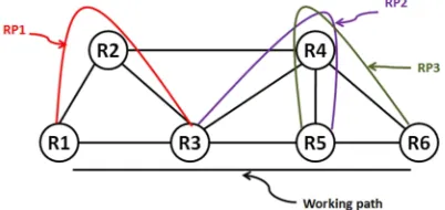
Link recovery provides recovery paths to protect each link on the working path. That is link recovery requires multiple recovery paths to protect a single working path as shown in figure 2. From figure 2, three recovery paths RP1, RP2 and RP3 (protecting link R1-R3, link R3-R5 and link R5-R6 respectively) are required to protect a single working path, R1-R3-R5-R6.
Fig. 2. Link recovery
2.3 Node recovery/restoration
Node recovery provides recovery paths to protect each node on the working path as shown in figure 3. From figure 3, node recovery requires two recovery paths, RP1 and RP2 (protecting nodes R3 and R5 respectively) to protect a single working path R1-R3-R5-R6.
Fig. 3. Node recovery
2.4 One-to-one recovery/restoration [8]
One-to-one recovery provides recovery paths to protect each element on the working path as shown in figure 4. From figure 4, one-to-one recovery requires 3 recovery paths, RP1, RP2 and RP3 (protecting node R3, node R5 and link R5-R6) to protect a single working path R1-R3-R5-R6.
Fig. 4. One-to-one recovery
From figure 2, figure 3 and figure 4, local repair (link/node/one-to-one recovery) is faster as compared to that of global repair (figure 1) since in local repair upstream node at the point of failure is responsible for switching the working path traffic on to the recovery path while in global repair ingress LSR is responsible for switching the working path traffic on to the recovery path. However, local repair requires more sources as compared to that of global repair.
Depending on the time when the recovery paths are detected there are two basic models of path recovery, rerouting/restoration and protection switching [6].
2.5 MPLS Rerouting Recovery Model
has occurred. Using MPLS rerouting, recovery path is used until the fault is repaired. MPLS rerouting results in efficient use of resources since recovery paths are created after the failure of link/node. The drawback of MPLS rerouting recovery model is the time required to compute and setup the recovery path after failure has occurred.
2.6 MPLS Protection Switching Recovery Model
In MPLS protection switching [6] recovery model one or more recovery paths are pre-computed to protect one or more working paths. The recovery path is usually disjoint from the working path to prevent any fault that can affect both the working and recovery path. MPLS protection recovery models results in fast recovery as compared to rerouting recovery model [6]. But disadvantage of protection recovery model is that it requires additional resources to setup the recovery path which remain unused until a fault occurs. Classification of MPLS protection switching recovery Model
Protection switching can also be classified as local repair and global repair/end-to-end repair which is also called as path-based protection. The path-based protection schemes can be further classified as 1+1 (dedicated ) path protection, 1:1 path protection, 1:N (many-to-one) path protection, M:N (many-to-many) path protection and Split Path Protection (protection using load balancing) [6]. Dedicated path-based (1+1) protection provides a dedicated recovery path for which resources are fully reserved. Though this scheme provides fast restoration while preserving QoS, it results in poor utilization of resources since resources are reserved but not used until failure of link and/node. The 1:1 path protection provides a recovery path for each working path. The 1:1 path protection scheme allows low-priority traffic to share the recovery path resources until the fault occurs. In 1:N path protection, N working paths are protected using a single protection path. In M:N path protection, N working paths are protected using M protection paths. Using 1:1, 1:N and M:N path protection schemes resources can be utilize efficiently since these protection schemes permit low priority traffic to utilize the recovery paths until the fault occurs. In case of failure of link/node on the working path, the low-priority traffic is preempted by the recovery path to carry the protected traffic. But disadvantage of these schemes is they may result in network instability because of preemption of low priority traffic. Using split path protection (protection using load balancing) multiple protection paths are used to carry the traffic of a working path.
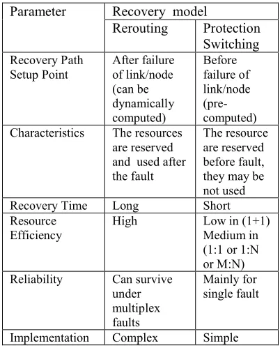
Below in table 1 we show the comparison of MPLS rerouting and protection switching recovery models.
Table 1: Comparison of MPLS Rerouting and Protection Switching Recovery Models
Parameter Recovery model
Rerouting Protection Switching Recovery Path
Setup Point
After failure of link/node (can be dynamically computed)
Before failure of link/node (pre-computed) Characteristics The resources
are reserved and used after the fault
The resource are reserved before fault, they may be not used
Recovery Time Long Short
Resource Efficiency
High Low in (1+1)
Medium in (1:1 or 1:N or M:N) Reliability Can survive
under multiplex faults
Mainly for single fault
Implementation Complex Simple In this section we discussed the basic mechanis-ms of MPLS-based recovery. In the next section we discuss various MPLS-based recovery schemes proposed by various authors.
2.7 MPLS-based Recovery Schemes Proposed by
Various Authors
The objectives of MPLS-based recovery schemes are to decrease recovery time, optimal use of resources, applicability of traffic protection at various granularities and different scopes, minimization of unprotected traffic degradation. Various recovery schemes have been proposed by several authors to meet these objectives.
Below we discuss the schemes based on global repair and local repair.
2.7.1 MPLS-based recovery schemes based on global repair
configured in advance. Network management system pre-computes the reactions to path failures and configures the routers accordingly. Their algorithm determines a set of end-to-end paths by fulfilling load balancing rules. Upon detecting path failures, the ingress router rebalances the traffic on the pre-computed recovery paths (as shown in figure 5). The authors used traffic engineering to improve path protection. But disadvantage of their scheme is due to load balancing the issue of reordering of packets may arise.
Fig. 5. NMS calculates and informs the backup paths to ingress router [9]
T. Ali et al. [10] have presented an algorithm which determines the most critical paths to avoid running the flows on these paths and attempt to set up working LSPs and back up LSPs on less critical paths. Haskin’s scheme [11] and Makam’s scheme [12] use protection switching model and global repair. Both 1:1 path protection and 1:N protection can be achieved with the approach proposed by D. Haskin et al. [11].
Various authors have proposed the solutions for MPLS-based recovery using the backup path sharing approach. The aim of backup path sharing is to reduce the total amount of bandwidth utilized by the backup paths.
Sriganesh Kini et al. [13], Murali Kodialam and T. V. Lakshman [14] in their work focuses on MPLS restoration functionality and schemes using sharing backup bandwidth which require to maintain additional information for each link about the bandwidth used by the working LSPs and the backup paths. K. Sriram et al. [15] have proposed an analytical model to compute the number of shared and dedicated backup paths. The authors have proposed an algorithm to efficiently manage backup paths while doing protection assignments. The set of backup paths that are dedicated to a particular protection group would be used before the shared backup paths to recover from faults. The Weidong Cui [16] proposes an algorithm for
backup path bandwidth sharing based on statistical aggregation. The key features of his proposal are backup path bandwidth allocation is not limited to single link/node failure, reduces overhead for information since no routing information is required, resourceful bandwidth distribution and low fatal failure probability. The author represents the relationship between the number of working paths, path failure probability of working paths and the amount of allocated bandwidth on the shared backup paths. By finding the appropriate amount of backup bandwidth the author proved that his proposed algorithm can utilize bandwidth more efficiently as compared to 1:1 path protection. ITU-T G.808.3 [17] offers the protection mechanism for connection-oriented layer networks. The mechanism in ITU-T G.808.3 used protection switching recovery model to maximize speed of recovery.
In this section we discussed the schemes based on global recovery. Next we discuss the schemes based on local recovery.
2.7.2 MPLS-based recovery schemes based on local repair
Ye. Wang et al. [18] have proposed Resilient Routing Reconfiguration (R3), a novel link-based protection scheme. R3 is capable enough to handle realistic failure scenarios and prioritized traffic. R3 performed flow-based protection routing using MPLS, MPLS-ff. Hashing technique is used to forward the traffic along the route. The hash of the packets belonging to the same flow should be equal at the same router.
Fig. 6. Figure showing normal flows [18]
Fig. 7. Restoration of traffic after failure [18]
Though R3 can handle multiple failures and ensures a congestion-free network but due to link-based protection, issue of resource efficiency may arise. Mingwei Xu et al. [19] have presented a protection scheme which is capable enough to handle single as well as multi link failure situations. Their scheme ensures the reduction in the backup cost.
Using Upstream Node Initiated Fast Restoration (UNIFR) [20] scheme, fast restoration can be achieved. UNIFR uses preestablished backup paths also called semi-global backup paths since upstream node adjacent to the fault reroutes the traffic which is affected due to the failure of link/node on the working path, from itself to the destination node. For example, from figure 8, there are two flows s-d, s1-d. Link i-j presents in both the flows. After failure of link i-j, the traffic of both the flows will take the backup path either b1 or b4.
Fig. 8. Backup paths using semi global paths [20]
Since UNIFR uses semi-global backup paths, it offers quick restoration as good as link-based scheme. Also resource efficiency using UNIFR is better than that of link-based scheme.
The network is able to share some bandwidth on common links among backup paths of the same service LSP, which is called intra-sharing (IETF RFC 4090, [8]). Dongmei Wang and Guangzhi Li [21] have proposed a recovery scheme, a solution for inter-sharing of bandwidth. Using their proposal bandwidth can be share between recovery paths of the same and different working LSPs. For example,
from figure 9 there are two working paths A-B and E-F having recovery paths A-C-D-B and E-C-D-F respectively.
Fig. 9. Backup path sharing (inter-sharing) example [21]
Common link C-D will share the bandwidth though both backup paths belong to the different working paths [21]. Faisal Aslam et al. [22] have proposed a backup path sharing recovery scheme. Using heuristic approach the authors accommodate maximum number of LSPs on the network is to maximize bandwidth sharing.
Reuven Cohen and Gabi Nakibly [23] have presented the solution for maximizing restorable throughput. By simulations the authors compared the performance of various MPLS recovery schemes and conclude that local recovery should be the preferred choice to maximize the revenue.
In this section we discussed various schemes proposed by various authors for addressing the issues of restoration and protection paths. The schemes discussed above are based on either dedicated path-based or link-based or one-to-one recovery scheme. In the next section we show our experimentation evaluation of dedicated path-based, link-based and one-to-one recovery schemes.
3 EXPERIMENTAL EVALUATION OF MPLS-BASED RECOVERY SCHEMES
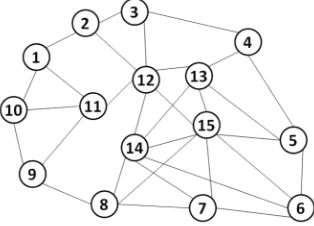
We have implemented dedicated path-based, one-to-one and link-based protection schemes using ns-2 on a synthetic network topology shown in figure 10. In the tables given below, the symbol ‘×’ in the column of working path or protection path shows that the demand cannot be routed or cannot be protected (due to insufficient resources) respectively.
Fig. 10. Network topology A
Table 2: Traffic configuration parameters for network topology A
Traffic Demand
Ingress- Egress
Bandwidth (Mbps)
d1 1-4 15
d2 8-4 10
d3 6-9 10
d4 8-4 10
d5 1-4 10
d6 1-6 15
d7 1-6 15
d8 6-9 10
d9 1-6 10
d10 8-6 10
For each of the simulated scheme the working path of each traffic demand is computed using constrained shortest path first (CSPF) algorithm [24].
In table 3, table 4 and table 5 given below, the column heading TD indicates traffic demand and Bw indicates bandwidth reservation in Mbps for protection paths.
Table 3 shows the working paths and protection paths using dedicated path-based protection scheme for network topology A. From table 3 we observe that using dedicated path-based protection scheme in network topology A, the total number of protection paths is 6, total working capacity reserved for routing the traffic demands is 90Mbps and protection capacity reserved is 65Mbps and number of fully protected demands is 6. A traffic demand is said to be fully protected if all links of its working path are protected.
Table 3: Protection paths using dedicated path-based protection scheme for network topology A
TD Working path
Protection path Bw
d1 1-2-3-4 1-11-12-13-4 15
d2 8-15-5-4 8-14-13-4 10
d3 6-7-8-9 6-15-12-11-9 10
d4 8-15-5-4 8-14-13-4 10
d5 1-2-3-4 1-11-12-13-4 10
d6 1-10-9-8-7-6 × --
d7 × -- --
d8 6-15-8-9 6-14-12-2-1-10-9 10
d9 × -- --
d10 8-15-6 × --
Table 4 shows the working paths and protection paths using link-based protection scheme for network topology A. From table 4 we observe that using link-based protection scheme in network topology A, total number of protection paths is 19, total working capacity reserved for routing the traffic demands is 80Mbps and protection capacity reserved is 225Mbps and number of fully protected demands is 5.
Table 4: Protection paths using link-based protection scheme for network topology A
TD Working path
Link to be protected
Protection paths
Bw
d1 1-2-3-4 1-2; 2-3;
3-4
1-11-12-2; 2-12-3; 3-12-13-4
15; 15; 15
d2 8-15-5-4 8-15; 15-5; 5-4
8-7-15; 15-6-5; 5-13-4
10; 10; 10
d3 6-7-8-9 6-7; 7-8;
8-9
6-14-7; 7-14-8; 8-14-12-11-9
10; 10; 10
d4 8-15-5-4 8-15; 15-5; 5-4
8-14-15; 15-6-5; 5-13-4
10; 10; 10
d5 1-2-3-4 1-2;2-3;
3-4
×; ×; × --; --; --
d6 1-11-12- 14-6
1-11;11-12; 12-14;14-6
1-10-11; 11-9-8-14-12; 12-13-14; 14-15-7-6
15; 15; 15; 15
d7 × -- -- --
d8 6-14-15-8-9
6-14; 14-15; 15-8; 8-9
6-5-13-14; 14-13-15; ×; 8-15-13-4-3-2-1-10-9
10; 10; --; 10
d9, d10
Table 5 shows the working paths and protection paths using one-to-one protection scheme for network topology A. From table 5 we observe that using one-to-one protection scheme in network topology A, total number of protection paths is 16, total working capacity reserved for routing the traffic demands is 90Mbps and protection capacity reserved is 190Mbps and number of fully protected demands is 4.
Table 5: Protection paths using one-to-one protection scheme for network topology A
TD Working path
Link (L)/ Node (N) to be protected
Protection paths
Bw
d1 1-2-3-4 N 2; N 3 ; L 3-4 1-11-12-3; 2-12-13-4; 3-12-13-4 15; 15; 15
d2 8-15-5-4 N 15; N 5; L 5-4 8-7-6-5; 15-13-4; 5-13-4 10; 10; 10
d3 6-7-8-9 N 7; N 8; L 8-9
6-15-8; 7- 14-12-11-9; 8-14-12-11-9 10; 10; 10
d4 8-15-5-4 N 15; N 5; L 5-4 8-14-6-5; 15-13-4; 5-13-4 10; 10; 10
d5 1-2-3-4 N 2; N 3; L 3-4
×; 2-12-13-4; × --; 10; -- d6 1-11-12-14-6 N 11; N 12; N 14; L 14-6 1-10-9-8-15-12; ×; 12-15-6; 14-13-5-6 15; --; 15; 15
d7 × -- -- --
d8 6-14-13- 5-4-3-2-1-10-9 N 14; N 13; N 5; N 4; N 3; N 2; N 1; N 10; L 10-9 ×; ×; ×; ×; ×; ×; ×; ×; × --; --; --; --; --; --; --; --; -- d9 1-2-3-4-5-13-14- 6 N 2; N 3; N 4; N 5; N 13; N 14; L 14-6 ×; ×; ×; ×; ×; ×; × --; --; --; --; --; --; --
d10 × -- -- --
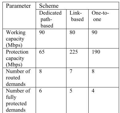
We summarize working capacity, protection capacity, number of routed demands and number of fully protected demands for network topology A in table 6. From table 6, the protection capacity required relative to its working capacity is lesser for dedicated path-based scheme as compared to link-based and one-to-one schemes. Also using dedicated path-based, more number of demands can be fully protected as compared to that of other simulated schemes.
Table 6: Working capacity, protection capacity, number of routed demands, and number of protected demands for network topology A
Parameter Scheme Dedicated path-based Link-based One-to-one Working capacity (Mbps)
90 80 90
Protection capacity (Mbps)
65 225 190
Number of routed demands
8 7 8
Number of fully protected demands
6 5 4
In this section we presented the simulation set-up and the observations of various MPLS-based recovery schemes for network topology A. In the next section, we carry out the result analysis.
4 RESULT ANALYSIS
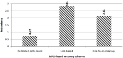
We compute the performance metrics discussed above for the dedicated path-based, link-based and one-to-one protection scheme using the results in table 6. We plot below the values of redundancy (figure 11), protection efficiency (figure 12) and node overhead (figure 13) for dedicated path-based, link-based and one-to-one schemes, for the network topology A.
Fig. 11. Redundancy vs. MPLS-based recovery schemes
Fig. 12. Protection efficiency (%) vs. MPLS-based recovery schemes
Fig. 13. Node overhead vs. MPLS-based recovery schemes
From figure 11, figure 12 and figure 13, dedicated path-based scheme requires fewer resources for protection since it results in lower redundancy, higher protection efficiency and lower node overhead as compared to that of other simulated schemes.
In the next section we present our conclusion and future work.
5 CONCLUSION
In this paper we have analyzed the MPLS-based recovery schemes proposed by various authors. Path-based schemes require fewer resources for protection than that of one-to-one and link-based schemes. Dedicated path-based scheme provides the best protection as it provides fast restoration while preserving QoS. In case of limited available resources for protection we proved that dedicated path-based scheme is better than one-to-one and link-based schemes.
However, in case of backbone network, failures of link or node are not regular issue and hence dedicated protection is not essential. Our future work is to improve dedicated path-based scheme while providing the required protection level.
6 REFERENCES
[1] E. Rosen, A. Viswanathan, and R. Callon, “Multiprotocol Label Switching Architecture”, RFC 3031, January 2001.
[2] J. Lawrence, “Designing Multiprotocol Label Switching Networks”, IEEE Communications Magazine, Vol. 39 , Issue 7, July 2001, pp. 134–142.
[3] Daniel O. Awduche, “MPLS and traffic engineering in IP networks”, IEEE Communications Magazine, Vol. 37, Issue 12, December 1999, pp. 42 – 47.
[4] D. Awduche, L. Berger, D. Gan, T. Li, V. Srinivasan, G. Swallow, “RSVP-TE: Extensions to RSVP for LSP Tunnels”, RFC 3209, 2001.
[5] D. Awduche, J. Malcolm, J. Agogbua, M. O’Dell, J. McManus, “Requirements for Traffic Engineering Over MPLS”, RFC 2702, September 1999.
[6] V. Sharma, Ed. Metanoia, Inc., F. Hellstrand Ed., “Framework for Multi-Protocol Label Switching (MPLS)-based Recovery”, IETF RFC 3469, February 2003.
[7] Ahn Gaeil, Jang Jongsoo, Chun Woojik, “An Efficient Rerouting Scheme for MPLS-Based Recovery and Its Performance Evaluation”, Telecommunication Systems, Vol. 19, 2002, pp. 481-495.
[8] P. Pan, G. Swallow, and A. Atlas, “Fast Reroute Extensions to RSVP-TE for LSP Tunnels”, IETF RFC 4090. May 2005.
SIGMETRICS’11, June 7–11, 2011, pp. 97-108.
[10] Ali Tizghadam, Alberto Leon-Garcia, “LSP and Back up Path Setup in MPLS Networks Based on Path Criticality Index”, IEEE International Conference on Communications, ICC, June 24-28, 2007, pp. 441 – 448.
[11] D. Haskin, R.Krishnan, “A Method for Setting an Alternative Label Switched Paths to Handle Fast Reroute”, <draft-haskin-mpls-fast-reroute-05.txt> , 2001.
[12] K.Owens, V.Sharma, S.Makam, and C.Huang, “A Path Protection/Restoration Mechanishm for MPLS Networks”, < draft-chang-mpls-protection-03.txt>, 2001.
[13] Sriganesh Kini, Murali Kodialam, Sudipta Sengupta, T.V., Lakshman and Curtis Villamizar, “Shared Backup Label Switched Path Restoration”, <draft-kini-restoration-shared-backup-01.txt>, IETF Internet draft, May 2001.
[14] Murali S. Kodialam and T. V. Lakshman, “Dynamic routing of locally restorable bandwidth guaranteed tunnels using aggregated link usage information”, INFOCOM IEEE Computer and Communications Societies, IEEE, Vol. 1, 2001, pp. 376–385.
[15] Kotikalapudi Sriram, David W. Griffith SuKyoung Lee and Nada T. Golmie, “Backup Resource Pooling in (M:N)n Fault Recovery Schemes in GMPLS Optical Networks”, OptiComm, Optical Networking and Communications. Vol. 5285, 2003, pp. 185-196.
[16]Weidong Cui, “Efficient Bandwidth Allocation for Backup Paths”, SPRING 2001
[17] International Telecommunication Union Recommendation ITU-T G.808.3: Generic protection switching – Shared mesh protection 2012.
[18] Ye. Wang, Hao Wang, Ajay Mahimkar, Richard Alimi, Yin Zhang, Lili Qiu, Yang Richard Yang, “R3: Resilient Routing Reconfiguration”, IEEE/ACM SIGCOMM’10, August 30–September 3, 2010, pp. 291–302. [19] Mingwei Xu, Meijia Hou, Dan Wang, Jiahai
Yang, “An efficient critical protection scheme for intra-domain routing using link characteristics”, Computer Networks, Elsevier. Vol. 57. Issue 1, pp. 117–133, 16 January 2013.
[20] Lu Ruan and Zhi Liu, “Upstream Node Initiated Fast Restoration in MPLS Networks”, IEEE ICC International Conference, Vol. 2, May 16-20, 2005, pp. 959-964.
[21] Dongmei Wang and Guangzhi Li, “Efficient Distributed Bandwidth Management for MPLS Fast Reroute”, IEEE/ACM Transactions on Networking, Vol. 16, Issue 2. April 2008, pp. 486-495.
[22] Faisal Aslam, Saqib Raza, Zartash Afzal Uzmi and Young-Chon Kim, “Bandwidth Sharing with Primary Paths for Protection Routing in an MPLS Network”, INFOCOM. 25th IEEE International Conference on Computer Communications Proceedings, April 23-29, 2006, pp. 1-6.
[23] Reuven Cohen and Gabi Nakibly, “Maximizing Restorable Throughput in MPLS Networks”, IEEE/ACM Transactions on Networking, Vol. 18, No. 2, April 2010. [24] Deepankar Medhi, Karthikeyan Ramasamy,
![Fig. 6. Figure showing normal flows [18]](https://thumb-us.123doks.com/thumbv2/123dok_us/1327901.1640978/4.612.327.492.537.603/fig-figure-showing-normal-flows.webp)
![Fig. 9. Backup path sharing (inter-sharing) example [21]](https://thumb-us.123doks.com/thumbv2/123dok_us/1327901.1640978/5.612.112.275.477.549/fig-backup-path-sharing-inter-sharing-example.webp)