Volume 1, Issue 8 (October2012) PP: 61-69
PERFORMANCE EVALUATION OF CONTROL STRATEGIES
FOR CMLI BASED STATCOM IN VOLTAGE REGULATION
Dr. Jagdish Kumar
Department of Electrical Engineering, PEC University of Technology, Chandigarh
Abstract:––In this article, performances of two control strategies are evaluated for cascade multilevel inverter based STATCOM for reactive power compensation and power system bus voltage regulation. In direct control scheme modulation index (switching angles) is varied at constant dc capacitor voltage in order to vary the output voltage of STATCOM while in case of indirect control scheme the dc capacitor voltage is varied at constant modulation index. Due to variation in modulation index, THD produced in output voltage varies while at constant modulation index THD can be kept at minimum level. On the other hand, output voltage variation is slow in case of indirect control scheme due to slow variation in dc capacitor voltage. The above facts have been verified by using digital simulation in MATLAB/SIMULINK environment on an 11-level cascade multilevel inverter based STATCOM under variations of load. The simulated results have been validated through experimental results on 11-level cascade multilevel inverter based STATCOM and it has been found that experimental results are in close agreement with simulated results.
Keywords:––cascade multilevel inverter, dc capacitor voltage, direct control scheme, indirect control scheme, modulation index, total harmonic distortion.
I.
INTRODUCTION
Voltage control in an electric power system is an important requirement for proper operation of electric power equipment to prevent damage such as overheating of generators and motors, to reduce transmission losses and to maintain the ability of the system to withstand disturbances and prevent voltage collapse. One of the major causes for voltage disturbances in power systems is reactive power drawn/supplied by various components of power systems, such as inductors, condensers, non-linear loads, power electronic converters etc., therefore, the control of reactive power in the power system must be regulated/compensated properly [1-2].
The reactive power in the system can be compensated by using conventional methods such as fixed capacitors, inductors, synchronous condensers etc or using power electronic switches based compensators such as TSC, TCR etc. [2-4] The above mentioned reactive power compensating devices are having disadvantages like less accuracy of compensation, slow response, less flexibility, more cost, operating dependency on system voltage etc.
In the last couple of years, commercial availability of power electronics based switches with high power handling capacity such as GTO thyristors, IGBTs etc. have led to the development of power electronic converters. A second generation FACTS device, using key component as voltage source inverter (VSI), has made significant impact in the field of reactive power compensation, and is known as static synchronous compensator (STATCOM). The STATCOM almost overcomes all the issues related with reactive power compensation and voltage regulation. One of the important merits of the STATCOM is that its operation does not depend on power system voltage [4]. For proper reactive power exchange with power system, the STATCOM output voltage needs to be controlled efficiently, and accordingly, two control schemes i.e. direct and indirect control strategies are used. Each of these control strategies has their merits and demerits in sense of response time, harmonic distortion in output voltage etc [5].
II.
STATIC
SYNCHRONOUS
COMPENSATOR
A. Basics
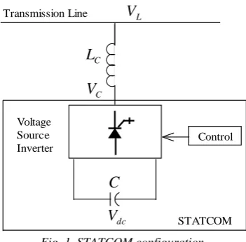
The basic STATCOM model consists of a voltage source inverter, dc side capacitors (C) with voltage Vdc on each capacitor, and a coupling reactor (LC) or a transformer. The ac voltage difference across the coupling reactor produces
C
V
dc
V
CL
C
L
V
Transmission LineControl Voltage
Source Inverter
STATCOM
Fig. 1. STATCOM configuration.
From topology point of view, the STATCOM can be classified into two categories: i) multi-pulse type and ii) multilevel type. In multi-pulse inverter topology, six-pulse inverter units are connected through a specially designed zigzag transformer to achieve high pulse inverter (i.e. 12, 24, 48-pulse) for better waveform and high power applications. The necessity of zigzag transformer which occupies more space and makes the configuration more complex is major demerit of it [7-8]. The alternative topology of STATCOM is based on multilevel inverters. The multilevel inverters are further classified as: diode-clamped type, flying capacitors type and cascade or isolated series H-bridges type. The different multilevel inverter topologies have their own merits and demerits depending on the number of components requirement, applications, configuration, cost, space requirement, modularity etc. Cascade multilevel inverter (CMLI) is considered most suitable topology for STATCOM for power systems voltage regulation applications [8-12].
B. Cascade Multilevel Inverter
The CMLI consists of a number of H-bridge inverter units with separate dc source for each unit and is connected in cascade or series. In Fig. 2 (a) two H-bridges (H1 and H2) are connected in cascade or series producing output voltage as
shown in Fig. 2 (b). Each H-bridge can produce three different voltage levels: +Vdc,0, and –Vdc by connecting the dc source
to ac output side by different combinations of the four switches. The ac output of each H-bridge is connected in series such that the synthesized output voltage waveform is the sum of all of the individual H-bridge outputs [9-12].
2
t
2Vdc
-2Vdc
1
2Vdc
-Vdc
1
2
vac
Vdc +_
Vdc +_
H1 H2
(a) (b)
Fig. 2. Configuration of single-phase five level cascade multilevel inverter.
By connecting the sufficient number of H-bridges in cascade and using proper modulation scheme, a nearly sinusoidal output voltage waveform can be synthesized. The number of levels in the output phase voltage is 2s+1, where s is the number of bridges used per phase. The Fig. 2 (b) shows five-level output phase voltage waveform using two H-bridges. The switching angles α1 and α2 are corresponding to H1 and H2 respectively while β1 = π-α1 and β2 = π-α2. In case of
11-level CMLI five H-bridges per phase are required and the magnitude of the ac output phase voltage is given by sum of output voltages due to each H-bridge.
C. Switching Angle Selection
(generally lower order) are eliminated [12-16]. Alternatively, the switching angles can be calculated by using some optimization based technique so that total harmonic distortion (THD) up to certain order (generally up to 49th order) is minimized instead of eliminating some individual harmonic components [17]. The details of switching angles calculation is given in [17]. In this work, the switching angles calculated using optimization based technique [17] which minimization overall THD is used.
III.
CONTROL
STRATEGIES
FOR
CMLI
BASED
STATCOM
For proper regulation of the ac system voltage, the output voltage generated by the cascade multilevel inverter needs to be varied smoothly and continuously so that the right amount of the reactive power can be exchanged with the ac system at all instants, therefore, an efficient control system is required. In this paper both direct and indirect control schemes have been implemented for this purpose [5-6], [18].
A. Direct Control Scheme
In case of direct control scheme, the output voltage is varied by varying the modulation index (m) i.e. by varying the switching angles of individual H-bridges of CMLI while keeping the dc capacitors voltages constant. The direct control scheme employed in this work is shown schematically in Fig. 3 for a CMLI having in general s number of H-bridges (for 11-level CMLI, s = 5). In general, the switching angles corresponding to each value of ‘m’ for each H-bridge are calculated off-line and are stored in a look-up table.
In Fig. 3, the reference ac system voltage (VL_ref) is compared with the actual voltage VL of the ac system and
corresponding error (i.e. the difference between these two) is processed through a PI controller (Controller 1) which produces an appropriate value of modulation index (m) needed for maintaining the ac system voltage at the desired level. Subsequently, the switching angles corresponding to the given m are obtained from the look-up table. In order to keep the dc capacitor voltages constant, a small amount of active power flow is made possible by phase shifting (lagging) the STATCOM voltage with respect to the ac system voltage by a small angle (φ), termed as load angle. The load angle is calculated by another PI controller (Controller 2) according to the difference between the reference capacitor voltage (Vdc_ref)
and the actual capacitor voltage (Vdc). The switching angles obtained from the look-up table are modulated (delayed or
advanced) by the load angle and finally, these modulated switching angles are used to generate the firing pulses to the semiconductor devices. Also, these modulated switching angles are swapped after each half cycle in order to balance the capacitor voltages [12].
Controller1
+ - Switching angles look-up table
STATCOM and Power System m Controller2 +
- Switching angles
modulation and swapping
1
2 s
Vdc VL Vdc Vdc_ref VL_ref
Fig. 3. Schematic diagram for direct control scheme of a STATCOM.
B. Indirect Control Scheme
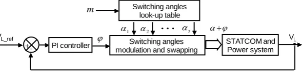
` In indirect control scheme the output voltage is controlled by varying the dc capacitor voltages at constant modulation index (i.e. at fixed switching angles). The indirect control scheme employed in this work is shown schematically in Fig. 4 for a CMLI having s number of H-bridges. As in direct control scheme, the switching angles for each H-bridge are calculated off-line and are stored in a look-up table. However, in this case, we can have fixed switching angles for a given value of m or if it is required to change m in that case we may have the look-up table.
PI controller +- Switching angles look-up table 1
2 s
Switching angles modulation and swapping
STATCOM and Power system m
VL_ref VL
Fig. 4. Schematic diagram of indirect control scheme for STATCOM.
In Fig. 4, the reference ac system voltage (VL_ref) is compared with the actual voltage VL of the ac system and
reasons as discussed in the case of direct control scheme. It is to be noted that as compared to the direct control scheme, in indirect control scheme, only one controller is required.
IV.
DIGITAL
SIMULATION
RESULTS
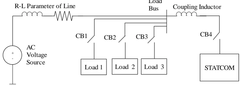
For validating the performance of the control strategies discussed in Section III, digital simulation studies of the 11-level CMLI STATCOM have been carried out on MATLAB/SIMULINK [20] environment under different conditions of load variations. The single line diagram of system simulated in SIMULINK [20] for these studies is shown in Fig. 5 and the parameters used are given in appendix.
In Fig. 5, the different loads are connected through circuit breakers CB1, CB2 and CB3 for testing the performance of the STATCOM under sudden load change conditions. CB1 is closed at t = 0.0 s while STATCOM is connected to load bus with the help of circuit breaker CB4 at t = 0.2 s. Initially when STATCOM is not connected, load bus voltage is less than 1 pu because inductive Load 1 is connected, therefore, error signal is generated which either increase modulation index (direct control) or capacitor voltage (indirect control) due to controller action.
+
-Load 1
Load 2
Load 3
STATCOM
CB1
CB2
CB3
CB4
Coupling Inductor
R-L Parameter of Line
Load
Bus
AC
Voltage
Source
Fig. 5. Single line diagram of system simulated in MATLAB for study of STATCOM operation.
A. Direct Control Scheme
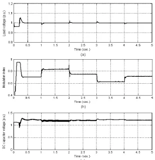
The Direct control scheme as discussed in Section III (shown in Fig. 3) has been implemented for this study. The parameters of PI controllers are designed by using Zeigler-Nichols method [19].For investigating the performance of the STATCOM with the designed control schemes under sudden load change conditions, sequence of events as mentioned in TABLE I has been followed in the simulation. The corresponding waveforms are shown in Figs. 6 (a)-(c).
TABLE I
Variations of different parameters of STATCOM and load bus voltage under load variations
Tim e (s)
Status of Circuit breakers
Load bus voltage
Total
Load (pu) Modulati on index STATCO M voltage Net flow of reactive power Dc Capacitor voltage
CB1 CB2 CB3 CB4 P Q
0.0 close
d open open open
below 1 pu
0.
2 0.4 increases
Not
connected No flow
precharge d value
0.2 close open open close d
rises and settles at
1 pu 0.
2 0.4
drops from initial value drops from initial value from STATCO M to load
bus
attains constant
value
1.0 close closed open close
falls and settles at
1 pu 0.
6 1.0 increases increases
from STATCO
M to load bus
constant
2.0 close close closed close
rises and settles at
1 pu 0.
8 0.4 decreases decreases
from STATCO
M to load bus
(less)
constant
3.0 close opene
d close close
rises and settles at
1 pu 0.
4 -0.2 decreases decreases
from load bus to STATCO M
constant
4.0 close open opene d close
falls and settles at
1 pu 0.
2 0.4 increases increases
from STATCO
M to load bus
Fig. 7 depicts the three-phase load voltage variations at and around 3 sec. to show the transient behavior of the system voltage. It can be seen from Fig. 7 that three-phase voltages are well balanced and desired voltage level is attained within a power cycle i.e. it operation is very fast.
Fig. 6. Variations of (a) load voltage, (b) modulation index and (c) dc capacitor voltage (direct control).
Fig. 7. Load voltage variation of three-phases at t = 3 sec. (direct control).
B. Indirect Control Scheme
The indirect control scheme as shown in Fig. 4 has been implemented and the parameters of PI controller are designed by following Z-N technique [19].
In order to compare the performances of two control strategies, the system is studied under similar sequence of load variations as discussed for direct control scheme. The corresponding waveforms are shown in Figs. 8 (a)-(c).
The sequence of events is similar to direct control scheme as given in TABLE I except that in place of modulation index, dc capacitor voltage will vary in similar manner at constant modulation index.
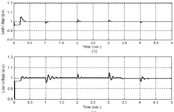
Fig. 8. Variations of (a) load voltage, (b) load angle and (c) dc capacitor voltage (indirect control).
Fig. 9. Load voltage variations of three-phases at t = 3 sec. (indirect control).
C. Comparison of Direct and Indirect Control Schemes
The comparison of direct and indirect control schemes for a CMLI STATCOM is carried out based on above simulation studies. The comparison is based on mainly two factors i.e. the speed of the response and THD in the output voltage under identical system and load parameter variations.
Fig. 10. Load voltage variation (a) direct control scheme and (b) indirect control scheme.
Fig. 11. Load voltage variation of three-phases at t = 1 sec. for (a) direct and (b) indirect control schemes.
THD in load voltage have also been determined using FFT analysis for both control schemes at different instants under load variation and these values of THD are given in TABLE II. It can be observed from this TABLE II that THD in load voltage at different instances of time is less in case of indirect control scheme as compared to direct control scheme irrespective of the nature of loads connected. This fact is due to change in THD level with modulation index in case of direct control scheme as compared to indirect control scheme where modulation index is kept constant [17].
TABLE II
Comparison of harmonic distortions in load voltage for direct and indirect controlled STATCOM
S. No. Time (s) THD in load voltage (%) Direct control Indirect control
1. 0.50 1.31 0.70
2. 1.50 0.93 0.74
3. 2.50 0.52 0.34
4. 3.50 0.59 0.33
5. 4.50 1.45 0.68
V.
EXPERIMENTAL
RESULTS
TABLE III
Parameters for hardware implementation of CMLI based STATCOM
S. No. Parameters 1-phase, 11-level 3-phase, 5-level
1. System voltage 173 V (line-to-line) 125 V (line-to-line)
2. Inductive load 1000 VA 500 VA
3. Current rating 3.33 A 2.3 A
4. Series inductance (LS) 3.38 mH 3.38 mH
5. Coupling inductance (LC) 16.85 mH 16.85 mH
6. DC capacitance for each H-bridge 1000 μF 1000 μF
7. Modulation index (indirect control) 0.9240 0.9240
8. Modulation index (direct control) 0.7000 (mmax = 0.95) 0.7000 (mmax = 0.95) 9. DC capacitor voltage 45 V ( m = 0.7000) 80 V (m = 0.7000)
10. Switching device MOSFET (400 V, 10 A) MOSFET (400 V, 10 A)
The performance of CMLI based STATCOM is to be investigated for load bus voltage regulation, a voltage sensor is used to measure the load voltage. The peak value of sensed load voltage is converted into an equivalent digital value using analog to digital converter (ADC) of dSPACE. The measured load bus voltage is compared with the reference value (desired value, VL_ref) for error generation. The difference between these two values (error) is processed through a PI controller and the controller output varies the voltage generated by CMLI according to control schemes implemented in Section III.
A. Direct Control Scheme
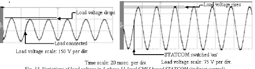
Fig. 12 demonstrates the voltage control capability of CMLI based STATCOM through direct control. An inductive load is connected suddenly to the load bus and due to this bus voltage goes down, the moment STATCOM is connected, it is restored to its normal value quickly.
Time scale: 20msec. per div., Load voltage scale: 150 V per div.
Fig. 12. Variations of load voltage for 1-phase 11-level CMLI based STATCOM (direct control).
B. Indirect Control Scheme
VI.
CONCLUSION
The performance of CMLI based STATCOM for load voltage regulation in the power system has been studied using simulation and experimentally. Both control schemes for load voltage regulation i.e. direct as well as indirect control schemes have been implemented successfully. In case of direct control scheme fast voltage regulation of load voltage is achieved as compared to indirect control scheme. The experimental results corroborate the results obtained through MATLAB simulation.
APPENDIX
Parameters of the ±5MVAr, 13.8kV STATCOM and power system are given below:
Base voltage = 13.8 kV, Base power = 5MVA, vs= 1.0, Short Circuit Capacity = 10 (pu), ω = 314 rad./sec., X/R Ratio = 4, m0 = 0.7000, RS (series resistance) = 0.45Ω, LS (series inductor) = 4.8 mH, RC (resistance of coupling inductor)
= 0.01 Ω, LC (coupling inductor) = 28 mH, C = 4800 µF, vdcref= 12500 V; Load 1 (P = 0.2 pu, Q = 0.4 pu), Load 2 (P = 0.4 pu, Q = 0.6 pu), Load 3 (P = 0.2 pu, Q = -0.6 pu (capacitive)), load voltage controller’s (direct control)
parameters: KP = 5, KI = 200; dc capacitor voltage controller’s parameters : KP = -3.15, KI = -643, load voltage controller
(indirect control) parameters: KP = 3.5, KI = 330, modulation index = 0.9240.
REFERENCES
1. Miller, T. J. E., Reactive Power Control in Electric System, John Wiley & Sons, 1982, pp 2-10, 51-56.
2. Hingorani, N.G. and Gyugi, L., Understanding FACTS, Concepts, and Technology of Flexible AC Transmission Systems, Standard Publishers Distributors, IEEE Press, 2000, pp 135-206.
3. Gyugi, L., Power Electronics in Electric Utilities: Static VAR Compensators, Proceedings of the IEEE, 1988, vol. 76, no.4, pp 483-494.
4. Gyugi, L., Dynamic Compensation of AC transmission Lines by Solid-State Synchronous Voltage Source, IEEE Transaction on Power Delivery, 1994, vol. 9, no. 2, pp 904-911.
5. Schauder, C. and Mehta, H., Vector analysis and control of advanced static VAR compensators, Proc. Inst. Elect. Eng., 1993, vol. 140, no. 4, pp. 299–306.
6. Sen, K. K., STATCOM-STATic synchronous COMpensator: Theory, Modeling, and Applications, IEEE PES 1999 Winter Meeting Proceedings, 1998, pp 1177-1183.
7. Soto, D., Green, T. C., A Comparison of High-Power Converter Topologies for the Implementation of FACTS Controllers, IEEE Transaction on Industrial Electronics, 2002, vol. 49, no.5, pp1072-1080.
8. Lee, C. K., Josheph S. K., Leung, S. Y., Ron Hui, and Henry Shu-Hung Chung, Circuit-Level Comparison of STATCOM Technologies, IEEE Transactions on Power Electronics, 2003, vol. 18, no. 4, pp. 1084-1092. 9. Lai, J. S., Peng, F. Z., Multilevel Converters-A New Breed of Power Converters, IEEE Transactions on Industry
Applications, 1996, vol. 32, no. 3, pp. 509-517.
10. Peng, F. Z., Lai, J. S., et al, A Multilevel Voltage-Source Inverter with Separate DC Sources for Static Var Generation, IEEE Trans. on Industry Applications, 1996, vol. 32, no. 5, pp. 1130-1138.
11. Peng, F. Z., McKeever, J. W. , and Adams, D. J., Cascade Multilevel Inverters for Utility Applications, IECON Proceedings (Industrial Electronics Conference), 1997, vol. 2, pp. 437-442.
12. Tolbert, L. M., Peng, F. Z., and Habetler, T. G., Multilevel converters for large electric drives, IEEE Transactions on Industry Applications, 1999, vol. 35, no. 1, pp. 36-44.
13. Rodriguez, Jose, Lai, J. S., and Peng, F. Z., Multilevel Inverters: A Survey of Topologies, Controls, and Applications, IEEE Trans. on Industrial Electronics, 2002, vol. 49, no. 4, pp. 724-738.
14. Chiasson, J. N., Tolbert, L. M., McKenzie, K. J., Du, Zhong, Control of a Multilevel Converter Using Resultant Theory, IEEE Transaction on Control Systems Technology, 2003, vol. 11, no. 3, pp. 345-353.
15. Chiasson, J. N., Tolbert, L. M., McKenzie, K. J., Du, A new approach to solving the harmonic elimination equations for a multilevel converter, in Proc. IEEE Industry Applications Soc. Annu. Meeting, Salt Lake City, UT, 2003, pp. 640-645.
16. Ozpineci, Burak, Tolbert, L. M., Chiasson, J. N., Harmonic Optimization of Multilevel Converters Using Genetic Algorithms, IEEE Power Electronics Letters, 2005, vol. 3, no. 3, pp.92-95.
17. Kumar, Jagdish, Das, Biswarup, and Agarwal Pramod, Optimized Switching Scheme of a Cascade Multilevel Inverter, Electric Power Components and Systems, 2010, vol. 38, issue 4, pp. 445-464.
18. Soto, Diego, and Pena, Ruben, Nonlinear Control Strategies for Cascaded Multilevel STATCOMs, IEEE Transactions on Power Delivery, 2004, vol. 19, no. 4, pp. 1919-1927.
19. Kumar, Jagdish, Das, Biswarup, and Agarwal, Pramod, Indirect Voltage Control in Distribution System using Cascade Multilevel Inverter Based STATCOM, ICPS-2011, IIT Madras, Chennai, pp. 1-6.