Abstract ─ Problems of rigid pavement can be due to two basic
causes. The first is deterioration or deficiency of the pavement itself. The other category deals with the structural adequacy of the pavement-base-subgrade structure. To minimize these problems, a rigid pavement called “Nailed Slab System” was proposed. The interaction of concrete slab, piles and soils creates a stiffer pavement structure and more resistant to traffic load. This paper aims to show the method to determine the deflection of the slab supported by piles due to point load. For this purpose, loading tests on small scale models of piles supporting slab were performed in the laboratory. The deflections along the slab observed from loading test were compared to those calculated using the theory of beam elastic foundation. The results of analysis showed that the proposed method to estimate deflections is fairly in accordance with the data observed.
Index Term-- Concrete slab, deflection, modulus of subgrade reaction.
I.
INTRODUCTION
Two basic causes which influence the failure of rigid pavement includes the deterioration or deficiency of the pavement itself and the other deal with the structural adequacy of the pavement-base-subgrade structure. Here, overload may be evidenced by pavement pumping, corner breaks, faulted joints and other defects [2][13]. To minimize these problems, Hardiyatmo [7] proposed a rigid pavement called “Nailed Slab System” (Fig.1). A Nailed Slab System is a reinforced concrete pavement (slab thickness between 12 - 20 cm) supported by mini piles with length of 150-200 cm and diameter of 15 - 20 cm. The interaction among concrete slab, piles and soil creates a stiffer pavement structure and more resistant to traffic load. In addition, installation of piles in the subgrade increases the effective modulus of subgrade reaction, and thus reduces the thickness of concrete slab. In addition, the installation of piles can prevent the forming of cavity between the slab and subgrade, so that the rigid pavement is more durable and stable to withstand the heavy traffic loads [7].
The design of rigid pavement using Nailed Slab System can be done by applying procedure recommended by AASHTO [2] or analysis based on structural analysis. This paper aims to show the method to analyze the deflection of the
Hary Christady Hardiyatmo, Dr., Ir., M.Eng., DEA. Lecturer of The Department of Civil and Environmental Engineering Faculty of Engineering,
Gadjah Mada University, Yogyakarta, Indonesia. e-mail: [email protected]. Phone +62-274-545675, Fax: +62-274-545676.
slab supported by piles due to point load. Some research has been conducted to study the behavior of the piles supporting the slab. Results of this study have shown that the installation of piles attached to the slab reduces the deflection of the slab. Analysis of the deflection of piled slab system may be done by applying theory of beam on elastic foundation and finite element method [6].
Fig. 1. Typical Nailed Slab System [7].
II. PROPOSED METHOD TO DETERMINE THE INCREMENT OF MODULUS OF SUBGRADE
REACTION
The ratio between the unit pressure and the corresponding deflection is termed the modulus of subgrade reaction and is mathematically expressed as:
k =
p (1)
where k = modulus subgrade reaction (kN/m3) p = intensity of soil pressure (kN/m2)
A = area of loaded plate (m2)
= deflection (m)
The value of k can be determined by performing a plate-load test. Due to piles installation in the ground, the value of
s
s
s s
s s s s s s
Piles: d = 0.20 m L = 1.5 – 2 m
s Traffic direction
a) Plan view
b) Side view
Concrete slab
Method to Analyze the Deflection of the Nailed
Slab System
subgrade reaction modulus increases. The equivalent modulus of subgrade reaction (k’) is defined by:
k’ = k + k (2) where k’ = equivalent modulus of subgrade reaction (kN/m3)
k = modulus of subgrade reaction (kN/m3)
k = increment of modulus of subgrade reaction due to piles (kN/m3)
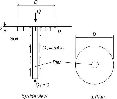
The basic unit to be considered is a single pile with an attached circular plate resting on soil. A loaded plate supported by a pile is presented in Fig.2. This figure shows the forces equilibrium when the plate is supported by a pile and loaded by a load P.
Fig. 2. Effect of pile installation to the soil bearing pressure under the loaded plate.
Ultimate carrying capacity of pile is expressed by the equation:
Qu = Qb + Qs (3) where Qu = ultimate carrying capacity of pile (kN)
Qb = ultimate base resistance (kN)
Qs = ultimate shaft resistance (kN)
Since the dimension of pile used in the piled slab system is very small, so the end bearing resistance of pile can be omitted (Qb = 0). The ultimate shaft resistance of pile is expressed by the equation:
Qs = Asfs (4) where fs= ultimate unit friction resistance on the pile shaft
(kPa)
As= surface area of the pile shaft (m2)
Ultimate unit friction resistance on the pile shaft can be expressed by the classical equation:
fs = adc + poKd tan d (5) where ad = adhesion factor
c = cohesion (kPa)
po= average overburden pressure (kN/m2)
Kd= coefficient of lateral soil pressure around the pile-soil
d= angle of internal friction between soil and pile shaft (degrees).
The displacement of the loading plate is different from the relative displacement between soil and pile. When the pile moves down due to loading, the soil under the plate also goes down. The displacement on the surface of loading plate () is always larger than the relative displacement between pile and soil (o). Since the relative vertical displacement between the pile and surrounding soil is very small, ultimate pile shaft resistance (Qs) has not been fully mobilized yet. Therefore, Qs = Asfs (6)
The mobilized unit pile shaft resistance can be expressed by:
Rs = fs (7) where = displacement factor. The value of is defined as a ratio between o and , as follows:
= o/ (8)
Subtituting (7) to (8), we can find:
) tan
( d u o d d
o
s a c p K
R
(9)
Pile friction modulus is defined as:
st
R
k
(10)where kt = pile friction modulus (kN/m3)
Rs = mobilized unit friction on the pile shaft (kN/m2)
= displacement of the pile head (m)
If the increment of modulus of subgrade reaction under the plate due to the piles installation is k, then the influence of the pile resistance to the increment of subgrade reaction can be determined using equation:
kA = kt As (11) We can solve,
AA R A A k
k s
s s
t
(12)
Qs = Asfs
Q
p
Qb ≈ 0
D
Soil D
wherek = increase of modulus of subgrade reaction due to pile installation
As = surface area of the pile shaft (m2)
A = area of the loading plate (m2)
From (2) and (11), the equivalent modulus of subgrade reaction can be expressed as:
A A R k k s s
' (13) By substituting (7) and (13), we obtain
s s f A A k k
' (14) Since o therefore,
s s o f A A k k 2 '
(15)
In (15), the increase in modulus of subgrade reaction due to pile installation is expressed by:
s s o
f
A
A
k
2
(16)Substituting (5) to (16), we can obtain the general equation to determine k, as follows:
)
tan
(
2 d u o d d
s o
K
p
c
a
A
A
k
(17)Equations (16) and (17) can be used to determined k, whereas the value of k’ can be calculated using (2).
It should be noted that area A depends on the distance of the pile. If the pile distance increases, then A also increases.In the design, it is assumed that the area supported by a pile is a square with width s, that is A = s2. With that assumption, and with references to (14) and (17), the increase in modulus of subgrade reaction can be expressed as:
s s
o
f
s
A
k
2 2
(18) Substituting for fs,)
tan
(
2
2 d u o d d
s o
K
p
c
a
s
A
k
(19)where k ' = modulus of subgrade reaction equivalent (kN/m3)
k = modulus of subgrade reaction of the plate load test (kN/m3)
o =relative displacement between pile and soil = plate deflection
A = area of loading plate (m2)
s = pile spacing (m)
Equations (18) and (19) can be used to determine the value of k in the design of Nailed Slab System.
III. ANALYSIS OF DEFLECTION
The settlement of pile-raft system has been analyzed using plate on piles and continuum method [4]. This analytical approach considers the raft as a plate, and soil as an elastic continuum. This method has been used to predict the load and settlement distribution for pile-raft system for the foundation of buildings [5].
An attempt was made to calculate the deflections, moments and shear forces due to the load acting on the flexible plate supported piles by applying the theory of beam on elastic foundation [8]. In this theory, the analysis of bending of beams on elastic foundation is developed on the assumption that the reaction forces of the foundation are proportional at every point to the deflection of the beam at that point. Although the formula beam on elastic foundation only suitable for the beam, Hetenyi [8] has shown that the formula can also be used to design two-dimensional structures. For the beam with finite length shown in Fig.3, the formulas for the deflection (), is expressed by equation:
b a b a l b a b a l x x x x b a l b a l x x l l kb P sin cosh cos sinh sin sin cos cosh sin sinh cos sinh sin cosh cos cosh sin cosh cos sinh cos cosh 2 sin sinh 1 2 2 ……….(20)where 4
4
EI
kb
k = modulus of subgrade reaction (kPa/m)
P = concentrated load acting on beam (kN)
b = width of beam (m)
E = modulus of elasticity of beam (kPa)
I = moment of inertia (m4)
a, b = distances from edge to the load P (m)
The value of x to use in (21) is from the end of the beam to the point for which the deflection is desired. If x is less than the distance a, use the equation as given, and measure x from
A. If x is larger than a, replace a by b in the equation, and measure x from B (Fig. 3).
IV. TESTING INVESTIGATION
In these cases, the real structures were modeled using small scale models.
Testing on model of concrete plate supported by piles subjected to point load has been conducted in the laboratory. Equipment used for this loading test includes a load reaction device, a hydraulic jack, concrete plate (supported and unsupported by pile), dial gauges, and miscellaneous tools. The test procedure suggested by ASTM D 1196 [2] was employed. Set up of load test on a reinforced concrete slab supported by piles subjected to concentrated load is shown in Fig. 4 and types of models of concrete plate supported by piles used in this study are shown in Fig. 5.
Fig. 4. Schematic set up of loading test on a concrete plate supported by a row of piles.
Fig. 5. Types of models of concrete slab.
The concrete slab was supported by 6 piles placed with pile distance center to center s = 0.20 m. The reinforced concrete piles have a diameter d = 0.04 m and lengths L = 0.40 m (a real structure that corresponds to geometrical scale 1 : 5). The soil used to conduct the loading test was clay soil (classified as CH) which has specific gravity Gs = 2.30, liquid limit LL = 68%, plastic limit PL = 29%, plasticity index PI = 39%. Clay fill was placed and compacted with water content w
= 42%, dry density d = 11,9 kN/m 3
and degree of saturation S
= 100%. Clay fill has an undrained cohesion cu = 21 kPa. Concrete slab has the modulus of elasticity Ec = 17 x 106 kPa. During the test, the compressive load was measured by pressure gauge attached to the jack and the deflection is measured by dial gauges attached to the reference beam. Loading was conducted by applying load sufficient to cause approximately a 0.25 mm (0.01 in.) deflection, and when the rate of increase in deflection is less than 0.03 mm/min (0.001 in./min), the reading of the deflection dial gauge is noted. Beside this type of test, loading tests on plate bearing without supporting pile were carried out using concrete circular plate with diameter 0.20 m and 0.04 m in thickness. Tension test on pile (L = 0.4 m, d = 0,04 m) was also conducted at continuous rate of uplift. The methods used for measuring force and the movement of the pile head are those used for compressive test.
V. RESULTS AND DISCUSSION
A. Results of Tension Test on Pile
Tension test on a pile was carried out to determine the unit friction resistance of pile. In this test, a pile with length L = 0.4 m and diameter d = 0.04 m embedded in clay fill was pulled out. Fig. 6 shows the relation between units frictions and vertical displacement obtained from this test. It can be seen from this figure that unit friction (fs) reaches a maximum value equal to 16 kPa at displacement of about 0.4 mm.
Fig. 6. Relation between mobilized unit friction versus displacement vertical, from tension test on pile (pile L = 0.4 m, d = 0.04 m).
Using the data from Fig. 6, the relation between modulus of friction (kt) and vertical displacement can be determined
0.2 m
0.2 m 0.4 m
0.04m
Pile
Plate
Plate
Side view
Pile
Plan
P
a) Concrete slab supported by a pile.
b) Concrete slab supported by a row of piles.
P P
0.2m 0.2 m 0.2 m 0.2m 0.2m
Piles
0.1m 0.1m
1,20 m
0.2 m
t = 0.04m
L = 0.4 m Slab
Side view
Plan
P P
and is presented in Fig.7. These results show that both the unit friction (fs) and modulus of friction (kt) reduce as pile displacement increases.
Fig. 7. Relation between modulus of friction (kt) versus displacement vertical,
from tension test on pile (pile L = 0.4 m, d = 0.04 m).
B. Results of Plate Load Test
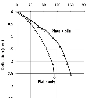
Plate load test was performed on a plate unsupported and supported by a pile. Concrete plates used in these tests have a diameter of 0.20 m and thickness of 0.04 m. Results of this test are presented in Fig. 8. This figure shows the relation between soil pressure (p) and deflection of the bearing plate (). It can be seen that installation of pile increase the bearing resistance of the soil. These results of the test also show that by increasing the slab deflection, the modulus of subgrade reaction is reduced. This can be attributed to the fact by the responds of soil bearing pressure is not proportional to the deflection. It can be seen in Fig. 8, the form of curve representing relations between the soil pressure and deflection is not straight line, but convex upwards.
Fig. 8. Results of loading test on circular concrete plate with and without pile.
Fig. 9. Influence of pile installation to the modulus of subgrade reaction.
Using the data from Fig. 8, the values of modulus of subgrade reaction for both types of model tests can be calculated and are presented in Fig. 9. In this case, the values of modulus of subgrade reaction are taken as the slope of line passing through the origin and the point on the curve corresponding to the soil pressure considered. In Fig.9, k
represents modulus of subgrade reaction resulted from load test for plate only, whereas k’ represents that resulted from
load test on plate supported by a pile. It is obvious that the effect of pile installation is to increase the value of modulus of subgrade reaction.
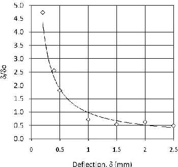
C. Relations Between /o and Slab Deflection ()
Considering (19), it can be seen that the increment of modulus of subgrade reaction (k) is a function of ando. In this study, the test plate is placed in clay with d = 0. Equation (19) can be rearranged as follows:
u d s o
c a A
A k
(21)
The values of k can be determined by subtracting k’ and k
from Fig. 9. By using the test results, where all the values of
As, A, , fs, cu and k have been known, the values of /o can be determined. Using cu = 21 kPa and ultimate unit friction obtained from Fig. 6, we can obtain the adhesion factor ad =
Fig. 10. Relation between /o and slab deflection ().
D. Analysis of Slab Deflection
The following discussion refers to the model tests which is loaded by a point load P = 4 kN. The deflections observed due to point load P = 4 kN along the loaded slab supported by one row containing 6 piles is presented in Fig. 11 for center loading, and Fig. 12 for edge loading.
Calculation of the deflection of piled slab system was done by using (20) and substituting all the data obtained from loading tests (distance between the piles s = 0.2 m, length L = 0.4 m, diameter d = 0.04 m, modulus of subgrade reaction k = 61417 kPa/m, cu = 21 kPa, As = 0.05 m2, A = 0.04 m2). Table I shows the values of modulus of subgrade reaction and /o used for these calculations. The results of calculation are presented in Fig. 11 for center loading, and Fig. 12 for edge loading, whereas Table 2 shows the comparisons between calculated and observed slab deflection on the point of loading. These results show that the theory of beam on elastic foundation (using parameter input modulus of subgrade reaction equivalent, k’) can be used to estimate slab deflection
adequately.
It should be noted that in this study, it was assumed that piles are only considered to increase the value of modulus of subgrade reaction. In fact, the piles in addition for providing the resistance to vertical force, also give moments resistances that reduce slab deflection.
Table I
Parameters used to calculate the slab deflection
Locations k
(kPa/m)
Observed deflection,
(mm)
/o
k
(kPa/m)
k’
(kPa/m)
Edge 61417 2.5 0.5 17730 79150
Center 61417 0.37 3.0 17973 79390
Table 2. Comparison between the calculated and observed slab deflections at point of loading
Locations Deflection, (mm)
Calculated Observed
Edge 1.94 2.25
Center 0.50 0.37
Fig. 11. Comparisons between calculated and observed deflection along the slab for center loading (P = 4 kN).
Fig. 12. Comparisons between calculated and observed deflection along the slab for edge loading (P = 4 kN).
These results indicate that for the design nailed slab system, it is required to takes the value of modulus of subgrade reaction using data obtained from plate load tests with the plate supported a pile. This is because the values of
/o may differ with different pile dimensions.
VI. CONCLUSIONS
Piles installed in the ground increases the values of modulus of subgrade reaction. Piles are also useful to keep the bottom of the slab in good contact with the subgrade, so that cavity formation under the slab can be minimized. The increment of modulus of subgrade reaction (k) due to pile installation in the ground is a function of ratio /o. The latter decreases, when the pile displacement increased. Equivalent modulus of subgrade reaction (k’) can be expressed as the sum
of modulus of subgrade reaction (k) obtained from plate load test and that from loading test on plate supported by a pile (k).
The results of analysis have shown that the theory of beam on elastic foundation using parameters input equivalent modulus of subgrade reaction (k’) give results reasonably
close to the deflection observed from the loading tests. For design nailed slab system, it is suggested to takes the value of modulus of subgrade reaction using data obtained from plate load tests with the plate supported by a pile.
ACKNOWLEDGMENT
The author would like to give acknowledgment to all those involved in the project, especially to Anas Puri, M.T., Prof. Bambang Suhendro, and Dr. T. Faisal Fathani for their valuable advice.
-0.20
0.00
0.20 0.40 0.60 0.80
1.00
-60 -40 -20 0 20 40 60
D
e
fl
e
ct
io
n
(mm
)
Distance from center (cm)
Calculated Observed
-0.50
0.00
0.50
1.00
1.50
2.00
2.50
-60 -40 -20 0 20 40 60
D
ef
le
ct
io
n
(mm)
Distance from center (cm)
REFERENCES
[1] AASHTO. (1988). “Manual on Subsurface Investigations”, Developed by the Subcommittee on Materials, American Association of State Highway and Transportation Officials, Washington, D.C.
[2] AASHTO. (1993). “Guide for Design of Pavement Structures”, American Association of State Highway and Transportation Officials, Washington, D.C.
[3] American Society for Testing & Materials. (2003).” ASTM Book of Standards, Vol. 4, Section 03, Road and Paving Materials; Vehicle-Pavement Systems”, ASTM International, West Conshohocken, PA. [4] Hain, S.J.(1975).”Analysis of Raft and Raft Pile Foundations”, In Soil
Mechanics: Recent Development. Proc. Symp. Univ.N.S.W. Australia, pp.213-254.
[5] Hain, S.J. and Lee, I.K. (1978), The Analysis of Flexible Pile Raft System”, Geotechnique, Vol.28, No.1:334.
[6] Hardiyatmo, H.C. and Suhendro, B. (2003). “ Pile Foundation With Thin Pile Cap As An Alternative To Solve Problems of Building on Soft Soils”, Competitive Grants Research Report, The Department of Higher Education, pp.M1-M7.
[7] Hardiyatmo, H.C. (2008). “Nailed Slab System for Reinforced Concrete Slab on Rigid Pavement”, Proceeding of the National Seminar on Appropriate Technology for Handling Infrastructure, MPSP-FT-UGM, Yogyakarta, Indonesia.
[8] Hetenyi, M., (1974). “Beams On Elastic Foundation”, Ann Arbor, The University Of Michigan Press.
[9] O’Neill, M.W., Vipulanandan, C. and Wong, D.(1990).”Laboratory Modeling of Vibro-driven Piles”, ASCE Journal of Geotechnical Engineering Division, Vol.116.
[10] Vesic, A.S. (1964).”Investigation of Bearing Capacity of Piles in Sand”, Duke University, Soil Mechanics. Laboratory, Publication, No.3.
[11] Whitaker, T. (1960).”Some Experiments on Model Piled Foundation in Clay”, Proc. Symposium on Pile Foundation, 6th
Congress of International Association Bridge and Structural Engineering, Stockholm, pp.124-139.
[12] Whitaker, T. (1957).”Experiments with Model Piles in Groups”, Geotechnique, Vol.7.
![Fig. 1. Typical Nailed Slab System [7].](https://thumb-us.123doks.com/thumbv2/123dok_us/1385753.1649429/1.612.322.551.283.488/fig-typical-nailed-slab-system.webp)