IJENS © June 2019 IJENS -IJMME -5757 -03 1911
Analytical Study of Effecting Labyrinth Seal
Geometry on Stability of Rotor System by
Using Bulk Flow Mode
Abstract-- In order to reduce the leakage in turbo machines, the straight labyrinth seals are used. Problems may happen in modern turbo-machines due to the unstable working conditions. This type of motion can occur when the labyrinth seals do not respond in a good manner for rotor dynamics and tangential force that act on the rotor in the whirl direction. So, the accurate predictions of dynamic behavior for labyrinth seal are very important to optimize the stability of the system. The bulk-flow model based on a computer code written in Fortran 90 has been used in this work. This research explains the effect of seal geometry (clearance and tooth angle) on rotodynamic coefficients which are dynamic and stiffness coefficients for seal with grooves on rotor and stator. These coefficients are calculated at three values of tooth angle (00, 200 , and 400) and three values of clearance (0.33, 0.4, and 0.5) at whirl frequency ratio of . The analysis of stability of the rotor system depends on the stiffness and damping coefficients. The resulted parameter from stiffness and damping coefficients is a tangential force, that can be considered as an indication of the system stability. It can be seen from the results that the increasing of stability of the system increased with increasing the clearance and tooth angle, that can be attributed to the decreasing of the cross coupled stiffness and damping coefficients and increasing of direct stiffness. In this study, a comparison was made between the stability of labyrinth seals when teeth fixed on the rotor with the other type when teeth are fixed on the stator . The results showed that the labyrinrh seal with (TOR) was more stabile than seal with teeth on on the stator. The main benefit that achieved by the research results can be illustrated by two sides. The first side, the research results explained that the analytical methods, when applied correctly can solve the problems of the stability of the rotor system that occurs in most of turbo machines. On the other hand, the results have shown that it is possible to reduce the
leakage of fluids and the unstable movement of rotary systems through the use of labyrinth seals designed with teeth attached to the rotor of labyrinth seal.
Index Term-- Labyrinth seal, Rotor dynamic, Radial and tangential force, Stability, Teeth on rotor.
1. INTRODUCTION
Most turbo machines may be subjected to internal leakage because high pressure working conditions.. Hence, to reduce this leakage, labyrinth seals are used. Generally, driving force components generated when the working fluids pass through labyrinth seals, therefore, these components of force lead to unstable vibration in the rotating systems. Child and Scharrer et al. [1,2,3] have been analyzed the rotor dynamic of labyrinth seals which designed with zero tooth angle by BFM. The fluid flow through the labyrinth seal is considered for 3-D and characterized to be unsteady, compressible and turbulent flow. Iwatsubo, et al. [4,2,5] have simplified the fluid flow model by considering the fluid flow as 1-D steady flow. The stability of rotor system can be affected by the influence of pre-swirl, which is the ratio of fluid velocity to whirl velocity. Huang, and Li, [6] studied the effect of pre-swirl on the rotor system stability . The results showed the instability of the system increase with high pre-swirl rate. Effect of rotating speed, inlet pressure, rotor vibration eccentricity ratio, and clearance on the rotor system stability have been studied by Zhang, et al., [7]. The results explained that the seal forces is linearly proportional with eccentricity ratio, vibration amplitude, and inlet pressure. Zhang assumed the fluid flow in the labyrinth cavity is a 1-D flow in the azimuthal direction The
Nehad abid Allah. H.
AL -Qasim Green University, Collage of
Water Resources Engineering, Babylon, Iraq
Atheer Saad Hashim*
AL -Qasim Green University, Collage of Water
Resources Engineering, Babylon, Iraq
Mushtaq F. Almensory
University of Al-Qadisiyah, College of Engineering- Mechanical Engineering Department Diwaniyah, Iraq [email protected] Diwaniyah, Iraq [email protected]
Salwan Obaid Waheed Khafaji
University of Babylon ,College of Engineering- Mechanical
axial influx and efflux due to of driving pressure flow through the seal gaps have been taken in consideration. Sun et al. [8] have studied the influence of swirl brakes on the stability of labyrinth seals using CFD model. Their results showed that the swirl brakes at the sealed entrance, the seal destabilizing forces, and cross-coupled stiffness coefficients decreased while the seal direct damping coefficients increased.Wanfu Zhang et al. [9] have studied the effect of rotational speed on the stability of labyrinth seal. Their results showed that the higher rotational speed will be beneficial to the stability improvement when the rotor is in tilting conditions. L.N. Butymova [10] studied the effect of changing the rotor diameter on fluid dynamic force. The results showed that when the of shaft diameter increased from 65 mm to 260 mm, the amplitude of the fluid dynamic force is increased as well due to increase the rotor area at a constant nominal pressure. Jia, X., et al, [11] studied the effect of shape of the teeth of labyrinth seal on the aerodynamic force. Their results showed that the changing of teeth from straight to T-teeth led to increase the radial force and decrease the leakage in seal.
The effect of different parameters such as tooth angle and seal clearance on the coeeficients of rotor dynamic have been deals in the present work In addition, the stability of rotor system using tangential force is studied as well
The designing of the labyrinth seal can be accomplished by designing the teeth of labyrinth seal and its positions (on the stator or on the rotor) and clearance between the rotor and stator. Labyrinth seal can be classified into three types (a- straight, b- stepped, and c-staggered) as shown in Figure (1).
Fig. 1. Labyrinth seals types.
2.GEOMETRY AND MATHEMATICAL MODEL
2.1. Seal geometry
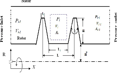
Figure (2) shows the 2-D straight labyrinth seal geometry. This figure has been show that the rotor is designed to be located at the central position with respect to the stator and knife teeth. Sixteen teeth are fixed on the rotor surface. These teeth generate fifteen cavities in the seal.
Fig. 2. Labyrinth Seal Geometry.
The geometrical parameters shown in the 2-D seal geometry are summarized in Table (1).
Table I
Seals Dimensions in the present study.
Parameter Value
Rotor radius, RS (mm) 75.6
Tooth thickness, ti (mm) 0.3
Tooth height, B (mm) 3.175
Cavity Length, L (mm) 3.175
Tooth angle, (deg) (changing) 0, 20, 40
Clearance, Cr (mm) (changing) 0.33, 0.4, 0.5
2.2. Governing Equations
Generally, two fluidforce components act on therotor of labyrinth seals relative to the whirl orbit; radial (Fr) andtangential (Ft)
force components. The tangential component (Ft) is considered to be the destabilizing force and it is modeled by cross coupled
stiffness (k) and direct damping coefficients. The tangential force can be calculated as:
(a)
IJENS © June 2019 IJENS
-IJMME -5757 -03 1911
Ft /e = k-CΩ (1)
Eq. 1 shows damping characteristic that produces negative tangential force. The generated radial force can be calculated by: .
(2)
/e = K+cΩ
r
F
It can be observed from the Eq. 2 that the direct stiffness coefficient (K) and cross coupling damping coefficient (c) are the main components of the radial force Fr . Eqs. (1) and (2) show that the rotor dynamic coefficients "K, k, C, and c " are the main
coefficients that effect on the stability of the rotor of seal. Fig.3 shows the rotor dynamics and the corresponding coefficients.
Fig. 3. Rotor dynamic coefficients.
Radial and tangential force equations are derived from solving the following governing equations:
a- Continuity Equation:
The fluid flow through the labyrinth seal is modelled by continuity equation which is written as: [12]
𝜕
𝜕𝑡 ( 𝜌𝑖𝐴) + 𝜌𝑖𝑉𝑖
𝑅𝑠𝑖 𝜕𝐴
𝜕𝜃+
𝜌𝑖𝐴 𝑅𝑠𝑖
𝜕𝑉𝑖
𝜕𝜃+
𝑉𝑖𝐴 𝑅𝑠𝑖
𝜕𝜌𝑖
𝜕𝜃 + 𝑞̇𝑖+1− 𝑞̇𝑖= 0
(3)
b- Momentum equation
Equation of momentum of fluid flow through the straight labyrinth seal is written as follows: [12]
𝜕
𝜕𝑡(𝜌𝑖𝑉𝑖𝐴) + 𝜌𝑖𝑉𝑖
2
𝑅𝑆𝑖 𝜕𝐴
𝜕𝜃+
2𝜌𝑖𝑉𝑖𝐴 𝑅𝑆𝑖
𝜕𝑉𝑖
𝜕𝜃+
𝑉𝑖 2
𝐴 𝑅𝑆𝑖
𝜕𝜌𝑖
𝜕𝜃 + 𝑞̇𝑖+1𝑉𝑖− 𝑞̇𝑖 𝑉𝑖−1
= − 𝐴
𝑅𝑆𝑖 𝜕𝑃𝑖
𝜕𝜃+ 𝜏𝑟𝑖𝑎𝑟𝐿𝑖− 𝜏𝑆𝑖𝑎𝑆𝐿𝑖
(4)
In order to model the shear stress on rotor (𝜏𝑟𝑖 ) and shear stress on stator (𝜏𝑠𝑖) which appeared in Eq(4) , Eq.(5) can be used:
[12]
τ =0.03955
𝑅𝑒1/4 𝜌 𝑉̅̅̅̅ 2
(5)
The momentume equation which is a zero order can be calculated by Eq.6
−𝑚̇𝑖−1𝑉𝑖−1+ 𝑚̇𝑖 𝑉 = 𝜏𝑟𝑖∗ 2𝜋𝑅𝑠 𝐿𝑖 𝑎𝑟− 𝜏𝑠𝑖2𝜋𝑅𝑠𝐿𝑖𝑎𝑠 (6)
where the dimensionless 𝑎𝑆 and 𝑎𝑟 are defined as
aS= {
2(Bi+ 𝐿𝑖) 𝐿𝑖
, for TOS,
1, fo TOR,
𝑎𝑟= {
2(Bi+ 𝐿𝑖) 𝐿𝑖
, for TOR,
1, for TOS,
The velocity in each cavity 𝑉𝑖 is obtained by an iterative procedure, where Eq.4 is simplified to the circumferential momentum equation (7). The following simplifying equation can be used to obtain Eq(7) as following:
𝜕
𝜕𝑡(𝜌𝑖𝑉𝑖𝐴) + 𝜌𝑖𝑉𝑖2
𝑅𝑆𝑖 𝜕𝐴
𝜕𝜃+
2𝜌𝑖𝑉𝑖𝐴 𝑅𝑆𝑖
𝜕𝑉𝑖
𝜕𝜃+
𝑉𝑖2𝐴 𝑅𝑆𝑖
𝜕𝜌𝑖
𝜕𝜃 + 𝑞̇𝑖+1𝑉𝑖− 𝑞̇𝑖 𝑉𝑖−1− 𝜕
𝜕𝑡 ( 𝜌𝑖𝑉𝑖𝐴) − 𝜌𝑖𝑉𝑖2
𝑅𝑠𝑖 𝜕𝐴
𝜕𝜃−
𝜌𝑖𝐴𝑉𝑖 𝑅𝑠𝑖
𝜕𝑉𝑖
𝜕𝜃−
𝑉𝑖2𝐴 𝑅𝑠𝑖
𝜕𝜌𝑖
𝜕𝜃 − 𝑞̇𝑖+1𝑉𝑖
+ 𝑞̇𝑖𝑉𝑖= − 𝐴 𝑅𝑆𝑖
𝜕𝑃𝑖
𝜕𝜃 + 𝜏𝑟𝑖𝑎𝑟𝐿𝑖− 𝜏𝑆𝑖𝑎𝑆𝐿𝑖
So, circumferential momentum equation can be written as
𝜌𝑖𝐴 𝜕 𝑉𝑖
𝜕𝑡 + 𝜌𝑖𝑉𝑖𝐴
𝑅𝑆 𝜕𝑉𝑖
𝜕𝜃+ 𝑞̇𝑖 (𝑉𝑖− 𝑉𝑖−1) = − 𝐴 𝑅𝑆
𝜕𝑃𝑖
𝜕𝜃 + 𝜏𝑟𝑖𝑎𝑟𝐿𝑖− 𝜏𝑆𝑖𝑎𝑆𝐿𝑖 (7) Equation (8) is used to calculate the leakage mass flow rate from cavity (i-1)th to (i)th cavity. [2]
𝑚̇ = 𝐴𝑁. 𝐶𝑂 . 𝜇 . √ 𝑃2
𝑖−1− 𝑃2𝐼
𝑅𝑇
(8)
The value of flow coefficient 𝐶𝑂 varies between 0.60 and 0.75 [13]. μ is the kinetic energy carry - over coefficient, which is calculated by Neumann [14] as shown:
𝜇 = √ NT
(1 − J)NT + J
with J=1-(1+16.6Cr/Li)-2 (9)
The annular area of the straight labyrinth seal can be defined as:
AN =π(2𝑅𝑠𝑖+ Cr)Cr, for the teeth on the stator.
AN =π(2(𝑅𝑠𝑖 + 𝐵𝑖) + Cr)Cr, for the teeth on the rotor
. (10) 2.3. Perturbation analysis
A perturbation analysis for governing equations (continuity, momentum, and mass flow rate equations) have been developed to the following approach [1] with the ratio of eccentricity," 𝝐 = e/Cr". These equations have been expanded by the technique of perturbation of variables as follows.
𝐻𝑖= 𝐶𝑟𝑖+ 𝜖𝐻1𝑖(𝑡, 𝜃) + ⋯ (11)
IJENS © June 2019 IJENS -IJMME -5757 -03 1911
𝑃𝑖= 𝑃0𝑖+ 𝜖𝑃1𝑖(𝑡, 𝜃) + ⋯,
𝑉𝑖= 𝑉0𝑖+ 𝜖 𝑉1𝑖(𝑡, 𝜃) + ⋯,
𝑞̇𝑖= 𝑞̇0𝑖+ 𝜖𝑞̇1𝑖(𝑡, 𝜃) + ⋯,
𝜏𝑠𝑖= 𝜏𝑠0𝑖+ 𝜖𝜏𝑠1𝑖(𝑡, 𝜃) + ⋯
and
𝜏𝑟𝑖= 𝜏𝑟0𝑖+ 𝜖𝜏𝑟1𝑖(𝑡, 𝜃) + ⋯ ,
(12)
Equation of continuity (3) can be modified as.
G1i ( 𝜕𝑃1𝑖 𝜕𝑡 + 𝑉0𝑖 𝑅𝑠𝑖 𝜕𝑃1𝑖 𝜕𝜃 + P0i 𝑅𝑠𝑖 𝜕𝑉1𝑖
𝜕𝜃) + G2i𝑃1𝑖−1+ G3i𝑃1𝑖+ G4i𝑃1𝑖+1= −𝐺5𝑖( 𝜕𝐻1𝑖 𝜕𝑡 − 𝑉0𝑖 𝑅𝑠𝑖 𝜕𝐻1𝑖 𝜕𝜃 ), (13)
The momentum equation can be written as.
𝑋1𝑖( 𝜕𝑉1𝑖 𝜕𝑡 + 𝑉0𝑖 𝑅𝑠𝑖 𝜕𝑉1𝑖 𝜕𝜃) + 𝐴0 𝑅𝑠𝑖 𝜕𝑃1𝑖
𝜕𝜃 + 𝑋2𝑖𝑉1𝑖− 𝑞̇0𝑉1𝑖−1+ 𝑋3𝑖𝑃1𝑖−1 + 𝑋4𝑖𝑃1𝑖 = 𝑋5𝑖𝐻1𝑖
(14)
where the coefficients:
𝐺1𝑖 , 𝐺2𝑖, 𝐺3𝑖𝐺4𝑖, 𝐺5𝑖, 𝑋1𝑖, 𝑋2𝑖, 𝑋3𝑖, 𝑋4𝑖 and 𝑋5𝑖 are functions to the zero order variables.
If the shaft perturbation assumed to be an elliptical orbit of semi axes a and b then:
𝐻1𝑖= −𝑅𝑒 { 𝑎 − 𝑏 2 𝑒 𝑖(𝜃+Ω𝑡)+𝑎 + 𝑏 2 𝑒 𝑖(𝜃−Ω𝑡)}. (15)
When forcing terms (15) are substituted into equations (13) and (14), the following formulas can be obtained:
𝑃1𝑖= 𝑅𝑒{𝑃𝑖+𝑒 𝑖(𝜃+Ω𝑡)+ 𝑃𝑖−𝑒 𝑖(𝜃−Ω𝑡)},
(16)
𝑉1𝑖= 𝑅𝑒{𝑉𝑖+𝑒 𝑖(𝜃+Ω𝑡)+ 𝑉𝑖−𝑒 𝑖(𝜃−Ω𝑡)},
(17)
The continuity equation (13) results in two equations for each cavity is:
𝑖 G1i [( 𝑉𝑜𝑖 𝑅𝑠𝑖
± Ω) 𝑃𝑖±+𝑃𝑜𝑖 𝑅𝑠𝑖
𝑉𝑖±] + G2i𝑃𝑖−1
± + G
3i𝑃𝑖
±+ G
4i𝑃𝑖+1
± = −𝑖𝐺
5𝑖 𝑎 ± 𝑏
2 (Ω ±
𝑉𝑜𝑖 𝑅𝑠𝑖
) .
(18)
The momentum equation (14) results in two equations for each cavity is:
i X1i[( Voi Rsi
± Ω) Vi±+ iAo Rsi
Pi±] + X2iVi ±− q0̇ Vi−1
± + X
3iPi−1
± + X
4iPi
±= −X
5i a ± b
2
(19)
Eq.(18) and Eq.(19) showed that each cavity can be expressed in a set of four linear equations. For more convenient , these equations can be written in a matrix form as following equation :
[𝐶𝑖−1]{𝑌𝑖−1} + [𝐶𝑖0]{𝑌𝑖 } + [𝐶𝑖+1]{𝑌𝑖+1} = {𝐴𝑖}
For each one of the cavities in labyrinth seal, there are system of four linear equations as shown in equation (19). This system of equations which are resulted is arranged as (4NC× 4𝑁𝐶) system of linear equations to determine the 4NC unknowns "𝑃𝑖+, 𝑃𝑖−, 𝑉𝑖+𝑎𝑛𝑑 𝑉𝑖−" for i=1,2,…NC. These of linear equations is written in a matrix form as following equation:-
[
. .
[Ci−1−1] [Ci−10 ] [Ci−1+1] [Ci −1] [Ci 0] [Ci +1]
[Ci+1−1] [Ci+10 ] [Ci+1+1]
. . ]{
. {Yi−1}
{Yi } {Yi+1}
. }
=
{ . {Ai−1}
{Ai } {Ai+1}
. }
(21)
By the technique which is proposed by [2], the system of equations (21) is solved using the Gauss elimination method to reach for the stiffness and damping coefficient equations. These coefficients are shown in figure (3) and can be computed as follows:
𝐾 = 𝜋𝑅𝑠𝑖𝐿𝑖∑ {𝑅𝑒 (𝑌̂1𝑖 𝑁𝐶
𝑖=1
+ 𝑌̂2𝑖) − (1 + 2𝐵𝑖
𝐿𝑖 )𝜏𝑟0𝑖
𝑃0𝑖
[𝐼𝑚 (𝑌̂1𝑖+ 𝑌̂2𝑖) +
1.75𝜏𝑟0𝑖 |𝜔𝑅𝑠 − 𝑉0𝑖|
𝐼𝑚 (𝑌̂3𝑖+ 𝑌̂4𝑖)
(22)
𝑘 = 𝜋𝑅𝑠𝑖𝐿𝑖∑ {𝐼𝑚 (𝑌̂1𝑖 𝑁𝐶
𝑖=1
+ 𝑌̂2𝑖) + (1 + 2𝐵𝑖
𝐿𝑖 )𝜏𝑟0𝑖
𝑃0𝑖
[𝑅𝑒 (𝑌̂1𝑖+ 𝑌̂2𝑖) +
1.75𝜏𝑟0𝑖 |𝜔𝑅𝑠 − 𝑉0𝑖|
𝑅𝑒 (𝑌̂3𝑖+ 𝑌̂4𝑖) +
0.125𝜏𝑟0𝑖 𝐷ℎ (𝐵 + 𝐶𝑟)2 ]}, (23)
𝑐 = 𝜋𝑅𝑠𝑖𝐿𝑖
Ω ∑ {𝑅𝑒(𝑌̂2𝑖
𝑁𝐶
𝑖=1
− 𝑌̂1𝑖) − (1 + 2𝐵𝑖
𝐿𝑖 )𝜏𝑟0𝑖
𝑃0𝑖
[𝐼𝑚 (𝑌̂2𝑖− 𝑌̂1𝑖) +
1.75𝜏𝑟0𝑖 |𝜔𝑅𝑠 − 𝑉0𝑖|
𝐼𝑚 (𝑌̂4𝑖− 𝑌̂3𝑖) ]},
(24)
𝐶 =𝜋𝑅𝑠𝑖𝐿𝑖
Ω ∑ {𝐼𝑚 (𝑌̂2𝑖
𝑁𝐶
𝑖=1
− 𝑌̂1𝑖) + (1 + 2𝐵𝑖
𝐿𝑖 )𝜏𝑟0𝑖
𝑃0𝑖
[𝑅𝑒 (𝑌̂2𝑖− 𝑌̂1𝑖) +
1.75𝜏𝑟0𝑖 |𝜔𝑅𝑠𝑖− 𝑉0𝑖|
𝑅𝑒 ( 𝑌̂4𝑖 −𝑌̂3𝑖
) +0.125𝜏𝑟0𝑖 𝐷ℎ (𝐵𝑖+ 𝐶𝑟)2
]}.
(25)
3. Results and discussion
3.1. Validation
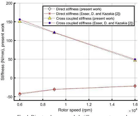
The results obtained in the present work have compared with the CFD model of results made on the same seal by Esser, and Kazakia, [2] to ensure the validity and accuracy of the calculations. The operating conditions of the seal, which used in the validation are summarized in Table (2).
Table II
Operating Conditions of the seal.[2]
Parameter Value
Rotating speed, (rpm) 3000,6000, 9000,16000
Inlet pressure, Pin (bar) 3.08
Outlet pressure, Pout (bar) 1.01
Inlet swirl velocity, (m/s) 60
Working fluid Teeth side
Air stator
IJENS © June 2019 IJENS
-IJMME -5757 -03 1911
Fig. 4. Direct and cross coupled stiffness vs. rotor speed.
Deviation percentages for the results are calculated. The maximum relative error between the results of direct stiffness coefficients is calculated and found to be equal to 3.22% when rotor speed is equal to 6000 rpm. While the maximum relative error (MRE) between the results of cross coupled stiffness coefficients is -5.55% when rotor speed is equal to 16000 rpm. The cefficients of direct and cross coupled damping of the present work are validated with results obtained by (Malvano, [15] as shown in figure (5).
Fig. 5. Direct and cross coupled damping vs. inlet tangential velocity.
Figure (5) shows that the direct damping coefficients decreased at (negative pre-swirl (- 40 – 0) m/Sec). However, it increased after the critical speed (0 mm/s) pre-swirl (0 – 40) m/Sec). While the cross coupled damping coefficients increased with increasing of pre swirl (tangential velocity). Compared to the results of Malvano [15], the coefficients of direct and cross coupled damping that obtained in the present work are a good agreement with, as the maximum relative error (MRE) of the results are calculated and found equal to 10%.
3.2. Effect Of teeth angle On Rotor Dynamic Coefficients.
Table III
Boundary Conditions of the seal
Parameter Value
Pressure ratio = Pout/Pin 0.34
Inlet Temperature, (T) 350 (K)
Inlet velocity, Vi 88 m/s
Whirl Frequency Ratio (/) ( 0.5)
Working Fluid
Teeth location Air Rotor
The direct stiffness coefficients against the clearance for labyrinth seal with tooth angles (=00, 200, and 400) have shown in Fig 6.
Fig. 6. Direct stiffness vs. clearance at different teeth angle.
This figure shows that the increasing in the clearance leads to increase the direct stiffness coefficients. Furthermore, it is noted that the values of direct stiffness are negative, that means the rotor system in stability case. This situation can be explained, when the operation speed of machine is greater than the critical speed, the negative stiffness can reduce the critical speed to a smaller value of RPM to generate a separation margin. On another side, if seal geometry is designed with a bigger tooth angle, the direct stiffness coefficients can be increased as shown. The cross coupled stiffness coefficient decreased with increasing clearance as shown in figure (7).
IJENS © June 2019 IJENS
-IJMME -5757 -03 1911
In order to show the stability of the rotor system, we must examine the coefficient of the cross-coupled stiffness, where increasing mean non-stability and vice versa. This figure shows the labyrinth seal which has higher teeth angle has a smaller cross coupled. The percentage of reduction in this coefficient are 11% and 66% at teeth angle of 200 and 400, respectively, compared to
that corresponding of a zero teeth angle. The above percentages are calculated for a labyrinth seal with clearance (0.4 mm). Direct damping varies with the clearance as shown in Figures (8). This shows there is a slight decrease in direct damping coefficient with increasing the clearance. In addition, it is worthy to note that the labyrinth seals with smaller tooth angles has higher direct damping coefficient.
Fig. 8. Direct Damping Vs. Clearance at different teeth angle.
The increasing of clearance between the stator and rotor of labyrinth seal leads to decrease the cross coupled damping coefficient as shown in figure (9). It can also be noted the labyrinth seal with higher teeth angle has a smaller cross coupled coefficients.
Fig. 9. Cross coupled damping vs. clearance at a different tooth angle.
for seal (TOR) on Radial and Tangential Forces
and teeth angle of Clearance
. Effect 2.1 . 3
Radial and tangential forces are calculated using equations (1) and (2) respectively. These equations show that the radial and tangential forces are a function of whirl speed and rotor dynamic coefficients. Hence the effect of clearance on these forces has been studied at different teeth angle. From a stability standpoint, the tangential force is the most influential because it is an indication for the destabilizing. The destabilizing effects are generated from the cross-coupled stiffness, k, and the stabilizing effects are generated from the direct damping, C. The radial force has a small influence on stability where the large negative direct stiffness values may reduce the natural frequencies.
Figures (10) and (11) show the effect of labyrinth seal clearance on radial and tangential forces at different teeth angle
respectively. It can be seen from figure (10) that changing the clearance of a labyrinth seal has a small effect on the induced forces in radial direction. Also, this figure shows there is decreasing in the radial force with increasing of teeth angle, that resulted from effect of teeth angle on the direct stiffness.
Fig. 10. Radial Force Vs, Clearance At Different Teeth Angle (TOR).
It can be predicted from figure (11) that the tangential force decreased with increasing clearance and teeth angle. From the design point of view, it is preferred that the tangential forces generated in the labyrinth are small and this can be obtained with the design of the labyrinth teeth at large angles. This means that the stability of rotor labyrinth seal can be increased with clearance and tooth angle increasing. This can be attributed to decreasing of the cross coupled with increasing clearance.
Fig. 11. Tangential force vs. clearance at different teeth angle (TOR).
. (TOR) of whirl speed on Radial and Tangential Forces . Effect
3.2.2
IJENS © June 2019 IJENS
-IJMME -5757 -03 1911
Fig. 12. Radial Force vs. whirl speed at tooth angle (400)
It can be seen from figure (12) that radial force decreased with increasing whirl speed until (1200 rad/Sec) when it starts to increase with whirl speed. The effect of whirl speed of the tangential force can be shown in figure (13). It is clear that the tangential force decreases with increasing the value of whirl speed.
.
0
= 40
λ
vs. whirl speed at Tangential force
. 13 . Fig
3.2.3. Effect Of Seal Clearance On Radial And Tangential Force With Teeth On Stator.
It can be noted that the arrangements of teeth of labyrinth seal from the main parameters may affect the stability of the rotor system. Thus, in the present section, effect of seal clearance on the radial and tangential forces is studied when the teeth are located on the stator.
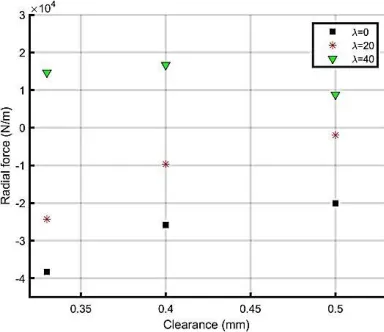
Effect of clearance on the radial force is explained in Figure (14). This figure shows the effect of clearance on the radial force at three angles of teeth (00, 200, and 400). The main prediction from this figure is theclearance and teeth angle increasing lead to
increase the radial force. The values of radial force are negative at tooth angles 00 and 200, because the direct stiffness coefficients
Fig. 14. Radial force vs. clearance of straight labyrinth seal (TOS), at different teeth angle.
On the other hand, the effect of clearance on the tangential forces was studied for labyrinth seal has teeth on the stator (TOS) as shown in figure (15). It is clear that the tangential force decreases with increasing values of clearance. This figure explains the relation between tangential force and clearance. The tangential force decreases as the labyrinth seal teeth angle increases.
Fig. 15. Tangential force vs. clearance of straight labyrinth seal (TOS) at different teeth angle.
A 5 % reduction in tangential force is evaluated for a labyrinth seal with clearance 0.4 mm in comparison with that of clearance (Cr=0.33 mm), while it becomes 15% for a labyrinth seal with Cr =0.5 mm in comparison with that of Cr =0.33 mm.So, it can be concluded from figure (15) that the stability of a rotor system with teeth on stator increases with the increasing of clearance and tooth angle. Figure(16) shows a comparison between the stability of TOS (Teeth on stator) and TOR (Teeth on rotor) straight labyrinth seals based on a labyrinth seal at different teeth angle (=00, 200 and 400). Figure (16) has been show that the tangential
force of (TOS) straight seal is greater than that of (TOR) straight labyrinth seal. The results revealed the TOR labyrinth seal is more stable than the TOS, as shown in figure (16).
IJENS © June 2019 IJENS -IJMME -5757 -03 1911 4.CONCLUSIONS
The performance of straight labyrinth seal with teeth on the rotor and on stator is studied by investigating rotor dynamic coefficients and tangential force at different parameters. The following remarks can be concluded from the results:
The increasing of clearance leads to increase the coefficients of direct stiffness and damping, while the coefficient of cross coupled stiffness and damping are decreased.
Higher Direct damping coefficients are induced in labyrinth seal with smaller teeth angle ().The results showed that the percentage of decrease in the coefficient of direct damping generated by the labyrinth seal is designed at a 20 ° tooth angle of 10% compared to the 0 ° tooth angle. While this percentage is 38 percent if labyrinth seal is designed at a corner of teeth of 400 .
Increasing of tooth angle and clearance lead to decrease the tangential force and increase the radial one.
Tangential force is decreased with whirl frequency increasing.
The stability of straight seal when teeth on rotor (TOR) is higher than that corresponding when the teeth on the stator (TOS).
Nomenclature
Cr: Seal radial clearance (mm)
C, c: Direct and cross coupled damping coefficients (N. Sec /m). e: eccentricity of the rotor (mm)
Fr, Ft: Radial and tangential forces (N/m).
K, k: Direct and cross coupled stiffness coefficients respectively (N/mm) "Greek symbol"
ϵ: Ratio of eccentricity
: Angular coordinate (rad)
: Angle of Teeth (deg)
τr : Shear stress resulted on rotor N/ m2
τs: Shear stress on resulted on the stator (N/ m2)
ω: Speed of rotation(rad/Sec) ρi: Density of fluid (kg/m3) Ω: Speed of whirl (rad/Sec).
5.REFERENCES
[1] Childs, D. W. and Scharrer, J. K., 1988, "Theory Versus
Experiment for TheRotor dynamic Coefficients of Labyrinth
Gas Seals" Journal of Vibration Acoustics Stress and
Reliability in Design-Transactions of the Asme, 110(3), pp. 281-287.
[2] Esser, D., and Kazakia, J. Y., 1995, “Air Flow in Cavities
of Labyrinth Seals" International Journal of Engineering
Science, 33 (15), pp. 2309-2326.
[3] Dereli, Y. and Eser, D., 2004, “Flow Calculations in Straight-Through Labyrinth Seals by Using Moody’s Friction-Factor
Model,” Association for Scientific Research, Mathematical
and Computational Applications, 9 (3), pp. 435-442
[4] Iwatsubo, T., 1980, "Evaluation of Instability Forces of
Labyrinth Seals in Turbines or Compressors," Proc. Proc.
Rotordynamic Instability Problems in High Performance Turbomachinery, NASA, pp. 139-167.
[5] Wei, Li., Yang, Y., and Sheng., 2010," Nonlinear Dynamic
Analysis Of A Rotor/Bearing/Seal System" Arch. Appl.
Mechanical
[6] Huang, D. and Li, X., 2004, "Rotor dynamic Characteristics of a
Rotor with Labyrinth Gas Seals. Part 2: A Non-linear Model,"
Proceedings of the Institution of Mechanical Engineers, Part A: Journal of Power and Energy 218(3), pp. 187-197
[7] Zhang, W., Yang, J., Cao, H., and Sun, D., 2011,
"Experimental identification of fluid induced force in labyrinth
seals," Journal of Mechanical Science and Technology, 25(10),
pp. 2485-2494, (1966).
[8] Sun, D.S.; Wang, D.; Fei, C.; Ai, Y.; and Wang, K. 2016. ''Numerical and experimental investigation on the effect of swirl
brakes on the labyrinth seals''. ASME, Journal of Engineering for Gas Turbines and Power, 138(3), 1-12.
[9] Wanfu Zhang , Yao Zhang , Jiangang Yang , Chun Li; 2016 "Influence of tilting rotor on characteristics of fluid-induced vibration for labyrinth seals' 'Journal of Vibro engineering, Vol. 18, Issue 8, p. 5416-5431.
[10] L.N. Butymova ; V.Ya.Modorskiia ; 2017, '' Numerical modeling of the labyrinth seal taking into account vibrations of the gas transmittal unit rotor in aeroelastic formulation'' 3rd International Conference “Information Technology and Nanotechnology”, ITNT-2017, 25-27 April 2017, Samara, Russia.
[11] Jia, X., Zheng, Q., Jiang, Y., Zhang, H.'' Leakage and rotordynamic performance of T type labyrinth seal'' Aerospace Science and Technology, Volume 88, Issue undefined, May 2019
[12] Omar M. Sahor.,1994 "Cavity pressures, velocity and leakage computation in straight through or stepped labyrinth seals"
M.S.C Thesis, Lehigh University.Using ANSYS-CFX", M.S Thesis, Virginia University.
[13] Gurevich, M.I., 1966, " Theory Of Jets In an ideal Fluid", Pergamon Press, 1966, pp.319-323.
[14] Neumann, K., 1964, “Zur Frage der Verwendung von
Durchblicktungen im Dampgturbinebau,” Maschinentechnik,
13(4).
[15] Malvano, R., 2002,” Rotor dynamic Coefficients for Labyrinth
Gas Seals Single Control Volume Model “ 70luwer Academic
publishers.
[16] Brennen,C. E, 1993, The Effect of Inlet Swirl on the
Rotordynamic Shroud Forces in a Centrifugal Pump " Journal of

![Table II Operating Conditions of the seal.[2]](https://thumb-us.123doks.com/thumbv2/123dok_us/1350553.1643529/6.612.59.575.222.453/table-ii-operating-conditions-seal.webp)