HARDWARE SOFTWARE CO-DESIGN FOR A
CLOSED LOOP CONTROL SYSTEM
B. Devi
1, Sanju Prakash. K
2,Vijay Kumar. S
3and Rohan P. Ganpati
4I.INTRODUCTION
With growing technology pertaining to industrial automation, the demand for control systems have increased. Systems in which the output quantity has no effect upon the input to the control process is called an open-loop control system. The goal of any control system is to measure, monitor, and control a process. We can accurately control the process by monitoring its output and feeding some of it back, to compare the actual output with the desired output so as to reduce the error and bring the output of the system back to the desired response. The quantity of the output being measured is called the feedback signal, and the type of control system which uses feedback signals to both control and adjust itself is called a closed-loop system. Generally, systems modelled for these applications are mostly mechanical and require large size hardware. Some important applications are rolling mills, paper mills, printing presses, textile mills, excavators, cranes, mine winders, hoists, machine tools, traction. In embedded systems, the software and hardware must be designed together to make sure that the implementation not only functions properly but also meet the performance, cost and reliability goals. This paper uses a software based PID control system which reduces the hardware requirement and thereby reducing the overall cost of the system. PID (Proportional, Integral, and Derivative) control is a widely-used method to achieve and maintain a process set point. The process itself can vary widely, ranging from temperature control to speed control in miniature electric motors to position control of an inkjet printer head. While the applications vary widely, the approach in each case remains quite similar
II.PROBLEM STATEMENT
Today, control system applications are mostly mechanical and requires large size hardware. Mass scale production of these systems becomes expensive. Usage of minimal hardware and maximal software ensures reduction in hardware and as a positive outcome, cost and component size are reduced. This approach leads to increase in robustness and flexibility of the system. Conventionally used method is to implement PID hardware suitable for a specific application. This restricts the usage of the same hardware for various other applications. Thus, the need for a
1
Assistant Professor, Electronics and Communication, Rajalakshmi Engineering College, Chennai, India 2 Student, Electronics and Communication, Rajalakshmi Engineering College, Chennai, India
3 Student, Electronics and Communication, Rajalakshmi Engineering College, Chennai, India 4 Student, Electronics and Communication, Rajalakshmi Engineering College, Chennai, India
DOI: http://dx.doi.org/10.21172/1.82.056
e-ISSN:2278-621X
Abstract- The implementation of a hardware software co-design in the field of control systems is explained in this paper. The architecture of such systems is a key aspect in the design process. The system is designed based on the ATmega 328P microcontroller. The functionality of such a system is shown using a case study – Speed control of a DC motor under loaded and unloaded condition. Usage of minimal hardware and maximal software ensures reduction in hardware and lessens expenditure of the system and the dependency of the control system on the hardware is reduced. This makes the system design simplified and compacted. Purpose of speed control is to reduce the error and drive the motor at a set speed under loaded or unloaded condition to a certain extent. The speed control of DC motor is crucial in applications where precision is of essence.
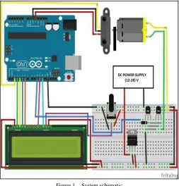
The system design comprises of an ATmega 328P microcontroller, 12V DC Supply, Voltage Regulator LM7812, Transistor n-p-n 2N2222, Diode, 12V DC Motor, IR Sensor, Potentiometer, 16x2 Liquid Crystal Display (LCD).
B. System operation
A 12V DC motor, for which the actual point is to be controlled based on the set point and load. Voltage regulator is used to maintain a steady voltage level in a circuit despite the fluctuations in the input. The output from the regulator is used to power the motor and the LCD. An LCD display is used to display the required input and output data for the system. An IR proximity sensor works by applying a voltage to IR light emitting diode which emit infrared light. This light hits the chopper of the motor and it is reflected back towards the sensor.
Figure 1. System schematic
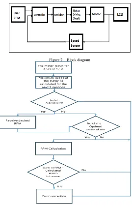
Figure 2. Block diagram
Figure 3. Flow diagram
The speed of the motor is calculated by noting the time taken by the motor to complete a certain optimal count of revolutions and computing with the equation: RPM = 60000*optimal count of revolution /time taken. The difference between the actual point and the set point gives the error. This error is diminished by the PID technique, where a certain amount of correction is being done to the original PWM signal.
C. Feedback
Figure 4. Motor response without feedback
The change in the speed of the motor when the user inputs a value is brought about by an algorithm which keeps checking the difference in the actual point and the set point and feeds a corrected PWM based on the value of the difference. This difference is calculated based on a PID control algorithm.
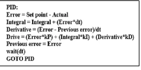
The Proportional–Integral–Derivative (PID) controller is a generic control loop feedback mechanism widely used in control systems. The PID control equation may be expressed as:
Correction = Kp*Error + Ki*Σ Error + Kd * dP/dT
Where, error is the difference between the set point and the actual point; Σ error is the summation of previous error values; and dP/dT is the time rate of change of speed.
Figure 5. Pseudocode for PID
Proportional gain (Kp): Larger proportional gain typically means faster response, larger the error, larger is the proportional term compensation. However, an excessively large proportional gain results in process instability and oscillation.
Integral gain (Ki): Larger integral gain implies steady-state errors are eliminated faster. However, the trade-off is a larger overshoot
Derivative gain (Kd): Larger derivative gain decreases overshoot but slows down transient response and may lead to instability due to signal noise amplification in the differentiation of the error.
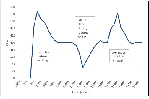
Figure 6. Motor response with feedback
D. Load stabilization
When a constant load is applied to the motor after a given settling time, the impact of the load will reduce the revolutions per minute.
Figure 7. Load –Unload characteristics
The reduction in the RPM creates an error between the set and the actual point. This error results in increasing the PWM based on the algorithm to diminish the error and the set is achieved. When the load is removed, the actual point shoots up to a value greater than the set point. This error is corrected by the algorithm and the motor settles at the desired speed.
IV
.C
ONCLUSIONThe motor response is observed to be nonlinear and the PWM mapping using the direct proportional method doesn’t make the motor run at the target RPM. This concludes that the motor doesn’t have a linear behaviour in the whole operating range. The feedback system adjusts the PWM in a calculated amount with the help of a PID controller technique. Thus, the implementation of this algorithm was investigated successfully using this case study
.
Scientific Engineering and Technology , ISSN:2277-1581 ,Volume No.5 Issue No.1, pp: 85-88
[5] Thirupathi Allam, Matla Raju, S.Sundeep Kumar,” Design of PID controller for DC Motor Speed Control Using Arduino Microcontroller [6] Wayne H. Wolf, “Hardware-Software Co-Design of Embedded Systems”, Proceedings of the IEEE, VOL. 82. NO. 7, JULY 1994
[7] PID Control: A brief introduction and guide, using Arduino http://www.academia.edu/7729313/PID_Control_A_brief_introduction_and_guide_using_Arduino
[8] Ziegler-Nichols Method