© 2017 AJAST All rights reserved. www.ajast.net
Optimal Reactive Power Flow by Flower Pollination Algorithm
M.Babu
1and S.Jaisiva
21UG Scholar, Department of EEE, IFET College of Engineering, Villupuram, India. Email: [email protected] 2Assistant Professor, Department of EEE, IFET College of Engineering, Villupuram, India. Email: [email protected]
Article Received: 24 March 2017 Article Accepted: 04 April 2017 Article Published: 07 April 2017
1.INTRODUCTION
The increased demand for electric power and the insufficient power generation and transmission facility forces the power system networks is being operated under stressed conditions. The security of a power system is under threat when it is operated at stressed conditions and may result in voltage instability. Nowadays voltage instability has become a new challenge to power system planning and operation. Insufficient reactive power availability or non-optimized reactive power flow may lead a power system to insecure operation under heavily loaded conditions [1]-[2]. By reallocating reactive power generations in the system by adjusting transformer taps, generator voltages and switchable VAR sources, the problem can be solved to a far extent.
Apart from the aforementioned methods, the system losses can also be reduced via redistribution of reactive power in the system for improving the stability of a power system. Large amount of reactive power flow in a system is indicated by the real power loss in the system. Therefore minimizing the real power loss ensures optimized reactive power flow (ORPF) through the lines. Reactive power optimization by real power loss minimization increases the power system economics to some extent. Reactive power optimization by minimization of real power loss has long been attempted for voltage stability improvement [3]-[4].
Optimal reactive power flow is an important tool in terms of secure and operation of power system. It is a powerful concept for power system operation and planning [5]-[6]. In ORPF, the network active power loss is reduced and voltage profile is improved while satisfying a given set of operating and physical constraints [7]-[8].
Reactive power flow is optimized by properly setting the values of control parameters. A number of conventional optimization methods have been exploited for this objective. Techniques such as nonlinear programming technique [9],
gradient based optimization algorithm are used to solve ORPF problem algorithms [10] are used to solve ORPF problem. But it has several disadvantages like large numerical iteration, insufficient convergence properties; which leads to large computation and more execution time.
The recently developed meta-heuristics based algorithms are proving better performance than the conventional methods. They find global best or nearly global best solutions for engineering problems. These algorithms are better utilized for power system optimization. Some of them are Tabu Search [11], Simulated Annealing (SA) [12], Genetic Algorithm (GA) [13], Evolutionary Programming (EP) [14]-[15] Hybrid Evolutionary Programming (HEP) [16], Particle Swarm Optimization PSO [17]-[19], Chaotic Ant Swarm Optimization (CASO) [20], Bacterial Foraging optimization (BFO) [21], Ant Colony Optimization (ACO) [22], Differential Evolution (DE) [23] and Quantum Genetic Algorithm (QGA) [24] are developed which provides fast and optimal solution.
Conventional methods are sensitive to initial guess of the search point where functions have multiple local minima and not efficient in handling problems of discrete variables [25]. In addition to this a lot of algorithms have been presented to solve optimal reactive power dispatch. Chien-Feng Yang proposed a system for limiting voltage variations by means of switchable shunt reactive compensation and transformer tap setting [26]. Other new optimization techniques are based on using fuzzy logic [27], lagrangian decomposition method [28].
FPA algorithm is a recent development and it very simple and easy to implement [29]-[30]. This algorithm has less number of parameters and has good convergence characteristics. Here in this paper, the FPA method is used for ORPD problem. The performance of this method is related with other algorithms to prove its efficiency.
A B S T R A C T
In power system operation, minimization of power loss in transmission lines and/or minimizing the voltage deviation at the load buses by controlling the reactive power is referred to as optimal reactive power flow (ORPF). ORPF is necessary for secured operation of power systems with regard to voltage stability. Here in this paper, the nature inspired Flower Pollination Algorithm (FPA) algorithm is introduced to solve multi constrained optimal reactive power flow problem in power system. Generator bus voltages, transformer tap positions and switchable shunt capacitor banks are used as variables to control the reactive power flow. Flower Pollination Algorithm was tested on standard IEEE 30 bus system and the results are compared with other methods to prove the effectiveness of the new algorithm. The results are quite emerging and the algorithm is found to be simple and easy to implement.
© 2017 AJAST All rights reserved. www.ajast.net 2. PROBLEM FORMULATION
The objective of this work is to optimize the reactive power flow in a power system by minimizing the real power loss and sum of load bus voltage deviation. An augmented objective function is formed with the two objective components and weights.
Objective function
The objective function of this work is to find the optimal settings of reactive power control variables including the rating shunt of var compensating devices which minimizes the real power loss and voltage deviation. Hence, the objective function can be expressed as:
(1)
Where w is the weighing factor for real power loss and voltage deviation and is set to 0.7.
1. Real power loss minimization (PL)
The total active or real power of the system can be computed as follows
]
Where, NL is the total number of lines in the system; Gk is the
conductance of the line ‘k’, Vi and Vj are the magnitudes of
the sending end and receiving end voltages of tie line; are angles of the end voltages.
2. Load bus voltage deviation minimization Bus voltage magnitude should be maintained within the allowable range to ensure quality service. Voltage profile is improved by minimizing the deviation of the load bus voltage from the reference value (it is taken as 1.0 p.u. in this work).
Constraints
The minimization problem is subject to the following equality and inequality constraints
Equality constraints Load Flow Constraints:
The equality constraints represent the load flow equations, which are given below for ith bus:
(4) (5) Where Pgi ,Qgi are the active and reactive power of ith
generator, PDi , QDi the active and reactive power of ith load
bus.
Inequality constraints Generator constraints.
Generator voltage and reactive power of ith bus lies between
their upper and lower limits as given below:
i= 1,2,....NG (5) i= 1,2,....NG (6)
Where , are the minimum and maximum voltage of ith generating unit and Qmingi , Qmaxgi are the minimum
and maximum reactive power of ith generating unit.
Load bus constraints.
i= 1,2,....NL (7) Where , are the minimum and maximum load
voltage of ith unit.
Transmission line constraints.
i= 1,2,...,NTL (8)
Where SL1 is the apparent power flow of ith branch and
is the maximum apparent power flow limit of ithbranch.
Transformer tap constraints.
Transformer tap settings are bounded between upper and lower limit as given below:
i= 1,2,...,NT(9)
Where , are the minimum and the minimum and maximum tap setting limits of ith transformer.
Shunt compensator constraints.
Shunt compensation are restricted by their limits as follows: ,i=1,2....,NC(10)
Where , are the minimum and maximum VAR injection limits of ith shunt capacitor.
3. FLOWER POLLINATION ALGORITHM
A new nature inspired optimization technique which has low computational time and high convergence speed called FPA is introduced recently [29]-[30]. In this algorithm, the candidate solutions are randomly spreaded over the search space. There is a convergence operator that has many inputs but only one output, which is named as the ‘‘centre of mass”, since the only output has been derived by calculating the centre of mass. The point representing the centre of mass that is denoted by Xc is calculated according to the following equation.
© 2017 AJAST All rights reserved. www.ajast.net The algorithm must create new members to be used in the
next iteration step. This can be done in various ways, the simplest one being jumping to the first step and creating an initial population. The algorithm will have no difference than random search method by so doing since latter iterations will not use the knowledge gained from the previous ones; hence, the convergence of such an algorithm will most probably be very low. In this work, the new candidates are generated around the centre of mass and knowledge of centre of mass of previous iteration is used for better convergence. The parameters to be supplied to normal random point generator are the centre of mass of the previous step and the standard deviation. The deviation term can be fixed, but decreasing its value along with the elapsed iterations produces better results.
Flower Pollination Algorithm applied to ORPF:
FP algorithm involves the steps shown below in reactive power optimization
Step 1: Form an initial generation of NP candidates in a random manner respecting the limits of search space.
Step 2: Calculate the fitness function values of all candidate solution by running the NR load flow.
Step 3: Determine the centre of mass which has global best fitness using equation (10).
Step 4: Calculate new candidate around the centre of mass by adding/subtracting a normal random number according to equation (11).
Step 5: Return to step 2 until stopping criteria has been achieved.
FLOW CHART:
Fig.1. Flow chart for FPA algorithm
4. NUMERICAL RESULTS AND DISCUSSIONS The performance of the proposed FPA algorithm based reactive power optimization method is tested in the medium size IEEE 30 bus system. The algorithm is implied in MATLAB environment and a Core 2 Duo, 2.8 MHz, 2GB RAM based PC is for the simulation purpose.
Minimization of objective terms.
The real power transmission loss and Voltage deviation is the major component of reactive power optimization and it needs more attention
Table 1.Control Variable Limits
The test system taken has six generating units connected to buses 1,2,5,8,11 and 13.
There are 4 regulating transformers connected between bus numbers 6-9, 6-10, 4-12 and 27-28.
Two shunt compensators are connected in bus numbers 10 and 24.
The system is interconnected by 41 transmission lines.
The control variables are generator’s voltages, tap settings of the regulating transformers and var injection of shunt capacitors.
The different control variables are given in table 1.
S.No Control Variable Limit
1 Generator voltage
(VG)
(0.9-1.1) p.u.
2 Tap setting(TP)
(0.9 - 1.1) p.u.
3 MVAR by static
compensators (Qsvc)
© 2017 AJAST All rights reserved. www.ajast.net Table 2.Optimal Control Variables:
The optimal control variables of the overall system obtained by FPA algorithm for this case are
shown in table 2.
Table.3 Voltage deviation value
In this case the FPA algorithm better optimize real power loss and Voltage deviation as show in table 3. The reduction in loss indicated by FPA algorithm is highly encouraging and it is only 4.807 MW.
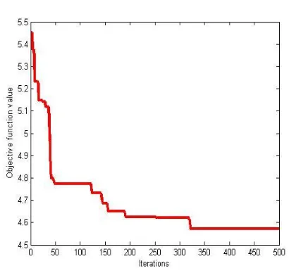
CHARACTERISTICS OF FPA
Fig .3 Convergence characteristics of FPA
The good convergence characteristics of FPA In the objective of real power loss minimization is plotted in figure.3
5. CONCLUSION
In this paper, a novel FPA Based optimization algorithm is proposed to solve multi-objective optimal reactive power flow problem. The performance of the proposed algorithm for solving ORPF problems is demonstrated using IEEE-30 bus system. The results are compared to those of other algorithms like PSO and BBO. The test results clearly exhibit that FPA outperforms other reported methods in terms of solution quality. The superiority of the proposed FPA method is more pronounced for large system as is evident from IEEE-30 bus system. From all simulation results it may finally be concluded that among all the algorithms, FPA based optimization method is capable of achieving global optimal solution. This paper shows that such tremendous results with different objective functions shows that makes the proposed FPA optimization technique is good in dealing with power system optimization problems.
REFERENCES
[1] P.K. Roy , S.P. Ghoshal , S.S. Thakur, “Optimal VAR Control for Improvements in Voltage Profiles and for Real Power Loss Minimization using Biogeography Based Optimization”, Electrical Power and Energy Systems, Vol. 43, No.1, pp. 830–838, December 2012.
[2] Abbas Rabiee, MaziarVanouni, MostafaParniani, “Optimal Reactive Power Dispatch for Improving Voltage Stability Margin Using a Local Voltage Stability Index”,
Energy Conversion and Management, Vol. 59, pp. 66-73, July 2012.
[3] KursatAyan, Ulaskilic, “Artificial Bee Colony Algorithm Solution for Optimal Reactive Power Flow”, Applied Soft
Computing, Vol.12, No. 5, pp. 1477–1482, May 2012.
[4] M. Varadarajan, K.S. Swarup, “Differential Evolutionary Algorithm for Optimal Reactive Power Dispatch, Electrical Power & Energy Systems, Vol. 30, No. 8, pp. 435–441, October 2008.
[5] AmitSaraswat, AshishSaini, “Multi-Objective Optimal Reactive Power Dispatch Considering Voltage Stability in Power Systems using HFMOEA”, Engineering Applications of Artificial Intelligence, Available online 18 July 2012.
[6] Altaf Q.H. Badar , B.S. Umre, A.S. Junghare, “Reactive Power Control Using Dynamic Particle Swarm Optimization for Real Power Loss Minimization”, Electrical Power & Energy Systems, Vol. 41, No. 1, pp. 133–136, October 2012.
[7] Reza Sirjani , Azah Mohamed, HussainShareef, “Optimal Allocation of Shunt Var Compensators in Power Systems Using a Novel Global Harmony Search Algorithm”,
Electrical Power & Energy Systems, Vol. 43, No.1, pp. 562–572, December 2012.
[8] SerhatDuman, UgurGuvenc , Yusuf Sonmez , NuranYorukeren, “Optimal Power Flow Using Gravitational Search Algorithm Energy Conversion and Management”, Vol. 59, pp.86–95, July 2012.
S.No Parameter Initial value
Optimal Value [FPA]
1 VG1 1.05 1.0631
2 VG2 1.04 1.0879
3 VG5 1.01 1.0243
4 VG8 1.01 1.0651
5 VG11 1.05 1.1000
6 VG13 1.05 1.0825
7 T6-9 1.078 1.1000
8 T6-10 1.069 1.0823
9 T4-12 1.032 1.0329
10 T27-28 1.068 1.0310
11 Q10 0.0 9.1438
12 Q24 0.0 11.4185
S.no Parameter
Initial
value FPA BBO PSO
1 Ploss 5.744 4.807 4.96 5.09
© 2017 AJAST All rights reserved. www.ajast.net [9] Mansour MO, Abdel-Rahman TM, “Non-linear VAR
Optimization Using Decomposition and Coordination”, IEEE Transactions on Power Apparatus Systems Vol. PAS-103, No. 2, pp. 246–55, February 1984.
[10] Mamandur KRC, Chenoweth RD, “Optimal Control of Reactive Power Flow for Improvements in Voltage Profiles and for Real Power Loss Minimization”, IEEE Transactions on Power Apparatus Systems, Vol. PAS-100, No.7, pp. 3185–3193, July 1981.
[11] Gan D, Qu Z, Cai H, “Large-Scale VAR Optimization and Planning by Tabu Search”, Electric Power Systems
Research, Vol. 39, No. 3, pp. 195–204, December 1996.
[12] Hsiao YT, Chiang HD, “Applying Network Window Scheme and a Simulated Annealing Technique to Optimal VAR Planning in Large-Scale Power Systems”, Electric Power Systems Research, Vol. 22, No. 1, pp.1–8, January 2000.
[13] Iba K. “Reactive Power Optimization by Genetic Algorithm”, IEEE Transactions on Power Systems, Vol.9, No. 2, pp. 685–692, May 1994.
[14] Lai LL, Ma JT, “Application of Evolutionary Programming to Reactive Power Planning- Comparison with Nonlinear Programming Approach”, IEEE Transactions on
Power Systems, Vol.12, No.1, pp.198–206, February 1997.
[15] Abido MA, Bakhashwain JM, “Optimal VAR Dispatch Using a Multi Objective Evolutionary Algorithm, Electric Power & Energy Systems, Vol.27, No. 1, pp.13–20, January 2005.
[16] Swain AK, Morris AK, “A Novel Hybrid Evolutionary Programming Method for Function Optimization”, Proc. 2000 Congress on Evolutionary Computation, Vol. 1, pp. 699–705, 2000.
[17] Yoshida H, Kawata K, Fukuyama Y, Takayama S, Nakanishi Y, “A Particle Swarm Optimization for Reactive Power and Voltage Control Considering Voltage Security Assessment”, IEEE Transactions on Power Systems, Vol.15, No.4, pp. 1232–1239, November 2000.
[18] Esmin AAA, Lambert-Torres G, de Souza ACZ, “A Hybrid Particle Swarm Optimization Applied to Power Loss Minimization”, IEEE Transactions on Power Systems, Vol. 20, No. 2, pp. 859–866, May 2005.
[19] Roy Ranjit, Ghoshal SP, “A Novel Crazy Swarm Optimized Economic Load Dispatch for Various Types of Cost Functions”, Electric Power & Energy Systems, Vol. 30, No. 4 , pp. 242– 253, May 2008.
[20] Cai J, Mab X, Li Q, Li L, Peng H, “A Multi-Objective Chaotic Ant Swarm Optimization for Environmental/Economic Dispatch”, Electric Power & Energy Systems, Vol.32, No.5, pp. 337– 344, June 2010.
[21] Ghoshal SP, Chatterjee A, Mukherjee V, “Bio-Inspired Fuzzy Logic based Tuning of Power System Stabilizer”,
Expert Systems with Applications, Vol. 36, No. 5, pp. 9281–9292, July 2009.
[22] Pothiya S, Ngamroo I, Kongprawechnon W, “Ant Colony Optimisation for Economic Dispatch Problem with Non-smooth Cost Functions”, Electric Power & Energy Systems, Vol. 32, No. 5, pp 478–487, June 2010.
[23] Shaheen HI, Rashed GI, Cheng SJ, “Optimal Location and Parameter Setting of UPFC for Enhancing Power System Security based on Differential Evolution Algorithm”,
Electric Power & Energy Systems, Vol. 33, No.1, pp. 94–105, Jan 2011.
[24] Lee JC, Lin WM, Liao GC, Tsao TP, “Quantum Genetic Algorithm for Dynamic Economic Dispatch with Valve-Point Effects and Including Wind Power System,” Electric Power & Energy Systems, Vol. 33, No. 2, pp. 189–197, February 2011.
[25] R. Mallipeddi , S. Jeyadevi , P.N. Suganthan , S. Baskar, “Efficient Constraint Handling for Optimal Reactive Power Dispatch Problems”, Swarm and Evolutionary Computation,
Vol.5, pp. 28–36, August 2012.
[26] Chien-Feng Yang , Gordon G. Lai , Chia-Hau Lee , Ching-Tzong Su , Gary W. Chang, “Optimal Setting of Reactive Compensation Devices with an Improved Voltage Stability Index for Voltage Stability Enhancement”, Electric Power & Energy Systems, Vol. 37, No.1, pp. 50– 57, May 2012.
[27] Reza Taghavi, Ali Reza Seifi ,Meisam Pourahmadi-Nakhli, “Fuzzy Reactive Power Optimization in Hybrid Power Systems”, Electric Power & Energy Systems, Vol. 42, No.1, pp. 375–383, November 2012.
[28] M. Granadaa, Marcos J. Riderb, J.R.S. Mantovani, M. Shahidehpour, “A Decentralized Approach for Optimal Reactive Power Dispatch Using a Lagrangian Decomposition Method”, Electric Power Systems Research, Vol. 89, pp. 148–156, August 2012.
[29] Osman K. Erol, Ibrahim Eksin, “A New Optimization Method: Big Bang–Big Crunch”, Advances in Engineering Software, Vol. 37, No. 2, pp. 106–111, February 2006.