277 | P a g e
IOT BASED SECURE DOOR LOCKING SYSTEM
Vedala Sharath
1, Ashok Kumar R
21
Department of Research and Development, Robolab Technologies Private Limited, Pune
2
Research Scholar, K L University, Vijayawada, AP
ABSTRACT
Security is the main issue that must be addressed in the present society. With the latest developments in
emerging technologies, IoT stands out to be the Cutting-Edge technology solving many security related
problems. Here is a Home security solution based on IoT, in this system we will have a wireless module which
connects to the Internet and communicates with the user through internet from anywhere in the world. User can
lock his Home’s door by using a mobile phone with an app installed in it. The main objective of this paper is to
embed a locking system in the door with two locking positions each individually controlled by the user using
mobile phone and intruder alert system when someone tries to open the lock manually. An additional feature
which gives better security option is, user can use this system in two modes. One is connecting to the internet
and the other one is Hotspot mode, where user can connect to local hotspot created by the system and monitor
the home in and around about a range of 30meter.
I.
INTRODUCTION
As mentioned, the aim of this project is to solve one of the security issues prevailing in the present society. It has been very difficult for people to have better security solutions even though in the improved technological situations. IoT has proven to provide many security solutions and this paper proposes an optimum solution addressing on such issue. Various systems have already been proposed in the field of home automation using Bluetooth, ZigBee and RF modules. All the previous systems lacked wide range of accessibility, secure alert system and Monitoring system. In this system, it is not the lock but a brand-new Door is made with good mechanical arrangement and Robust locking system without losing the original essence of the Door. As the device is connected to Internet it can be controlled from any place with internet connectivity. This system is also embedded with Security alert system using a sensor acquisition and mobile application alerts user about the successful locking which user can monitor any point of time using mobile phone. The mechanical arrangement of door in this system provides two locking modes.one is Normal Locking mode and the other is Advanced locking mode. In the Normal mode, the locking system at the center of the rear face adjoining the free-corner of the door latches with the door wall mount, while in the advanced mode along with the center latch the other two locking systems present at the top and bottom of rear face of the door latches ensuring a robust contact.
II.
METHODOLOGY
data base to the Door-locking system. This type of communication generally uses JSON data format for communication. The advantage of JSON format is light data weight and high speed communication. This communication starts with our mobile phone installed with Android application implementing MQTT protocol/TCP IP with data being JSON format. Once the data is sent from your mobile phone at an IP address assigned to your ESP-12E module. First the data reaches the cloud and then from cloud to the Door-locking system. The Data received by ESP-12E is processed and fed to a servo motor which rotates accordingly to lock the door at different positions as specified by the mode of operation. This lock also has a key hole to confuse the intruders and acts as security alert system with a sensor placed at the rear side of it.
III.
PROPOSED SYSTEM
Figure1: Block Diagram
IV.
ESP-12E
Figure 2: ESP 8266 Block diagram
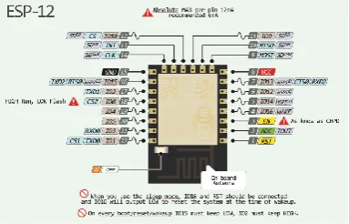
ESP-12E is loaded with NodeMCU firmware and coded using Lua script. NodeMCU is an eLua based
firmware for the ESP8266 Wi-Fi SOC from Espressif. The firmware is based on the Espressif NON-OS SDK
and uses a file system based on spiffs. The code repository consists of 98.1% C-code that glues the thin Lua
veneer to the SDK.Lua is an extensible, lightweight programming language written in C. It was designed from
the beginning to be a software that can be integrated with the code written in C and other conventional languages. This integration brings many benefits. For this, Lua has a safe environment, automatic memory
management, and good facilities for handling strings and other kinds of data with dynamic size.
Figure 3: ESP-12E Pinout
Features
• 802.11 b/g/n
• Integrated low power 32-bit MCU • Integrated 10-bit ADC
• Integrated TCP/IP protocol stack
• Integrated TR switch, LNA, power amplifier and matching network
• Integrated PLL, regulators, and power management units • Supports antenna diversity
• Wi-Fi 2.4 GHz, support WPA/WPA2 • Support STA/AP/STA+AP operation modes
• Support Smart Link Function for both Android and iOS devices • Support Smart Link Function for both Android and iOS devices
• Deep sleep power < 5uA
• Wake up and transmit packets in < 2ms
• Standby power consumption of < 1.0mW (DTIM3) • +20dBm output power in 802.11b mode
• Operating temperature range -40C ~ 125C
V.
DOOR WITH ITS LOCKING AND UNLOCKING MECHNISM
The mechanism is designed in a way to provide two different locking features to a user, the mechanical arrangement of door in this system provides two locking modes.one is Normal Locking mode and the other is Advanced locking mode. In the Normal mode, the locking system at the center of the rear face adjoining the free-corner of the door latches with the door wall mount, while in the advanced mode along with the center latch the other two locking systems present at the top and bottom of rear face of the door latches ensuring a robust contact. The Mechanical design of the system consists of a crank with links involved in it. This mechanism is popularly called as four bar Mechanism is follows as shown in figures 4,5 and 6.
A servo motor is attached at the center of the circular disk as shown in above figures. When the ESP-12E receives data for locking and unlocking. The servo motor rotates which actuates the circular disk’s rotation making the links move in and out of the door ensuring latching and unlatching.
Figure 4: Showing robust locking Figure 5: showing simple locking
design (Advanced mode) design (Normal mode)
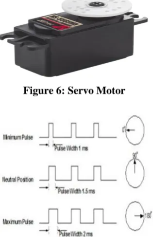
The amount of power applied to the motor is proportional to the distance it needs to travel. So, if the shaft needs to turn a large distance, the motor will run at full speed. If it needs to turn only a small amount, the motor will run at a slower speed. This is called proportional control. How do you communicate the angle at which the servo should turn?
The control wire is used to communicate the angle. The angle is determined by the duration of a pulse that is applied to the control wire. This is called Pulse Coded Modulation. The servo expects to see a pulse every 20 milliseconds (.02 seconds). The length of the pulse will determine how far the motor turns. A 1.5 millisecond pulse, for example, will make the motor turn to the 90-degree position (often called the neutral position). If the pulse is shorter than 1.5 ms, then the motor will turn the shaft to closer to 0 degrees. If the pulse is longer than 1.5ms, the shaft turns closer to 180 degrees. As you can see in the picture, the duration of the pulse dictates the angle of the output shaft (shown as the green circle with the arrow). Note that the times here are illustrative and the actual timings depend on the motor manufacturer.
Figure 6: Servo Motor
Figure 7: Pulse Width Modulation required for Servo Motor
VI.
SECURITY ALERT SYSTEM
In the security alert system, there is a sensor which is placed near the keyhole at rear side of the door to detect any intruder trying to open the door. When the sensor finds a detection the Alarm rings for about 5 mins and sends the date and time of detection to the user via internet which is notified to the user at that instant as a notification in Android phone.
Figure 8: proximity sensor
When the infrared can read back the infrared beams that it sends out, then this means the path of the infrared is impeded and there is an object nearby. If the sensor cannot read back the infrared beams it sends out, this ensures no object in front of the sensor.
Features:
Proximity Sensors detect an object without touching it, and they therefore do not cause abrasion or damage
to the object.
No contacts are used for output, so the Sensor has a longer service life (excluding sensors that use magnets).
Unlike optical detection methods, Proximity Sensors are suitable for use in locations where water or oil is
used.
Proximity Sensors provide high-speed response, compared with switches that require physical contact.
Proximity Sensors can be used in a wide temperature range.
Proximity Sensors are not affected by colors.
VII.
INTERNET PROTOCOLS
MQTT stands for Message Queuing Telemetry Transport. It is a publish/subscribe, extremely simple and lightweight messaging protocol, designed for constrained devices and low-bandwidth, high-latency or unreliable networks. The design principles are to minimize network bandwidth and device resource requirements whilst also attempting to ensure reliability and some degree of assurance of delivery. These principles also turn out to make the protocol ideal for the emerging “machine-to-machine” (M2M) or “Internet of Things” world of
connected devices, and for mobile applications where bandwidth and battery power are at a premium.
Applications:
Facebook currently uses MQTT for their messenger app, not only because the protocol conserves battery
power during mobile phone-to-phone messaging, but also because despite inconsistent Internet connections across the globe, the protocol allows messages to be delivered efficiently in milliseconds.
Amazon Web Services (AWS) supports MQTT, as well as HTTP, for connecting remote devices to the
Amazon IoT cloud.
The EVRYTHNG IoT platform uses MQTT as an M2M protocol for millions of connected products
VIII.
CONCLUSION
The main aim of this project is to provide a security solution allowing user to rely on a technical solution for the safety.
This system is cheaper.
It can have a user friendly mobile app to control the locking system.
It is robust and has different modes of operation.
It provides a security assistance.
But there should be a standardization in the door manufacturing which support the electronic and mechanical arrangement of the system. The other limitation would be building the cloud server for stable communication. In future we could also add a continuous monitoring system which could take photographs and also send live video to your mobile phone and also use some efficient mechanism to reduce the cost of manufacturing making system readily available for every user.
IX.
ACKNOWLEDGEMENTS
We gratefully acknowledge the guidance of Mr. Ashok Kumar, Associate Professor, Department of Computer Science & Engineering &Head Center for Excellence, Sphoorthy Engineering College, Hyderabad who was the constant source of inspiration and guidance to us.
REFERENCES
1)http://randomnerdtutorials.com/esp8266-web-server-with-arduino-ide/ 2) https://github.com/nodemcu/nodemcu-firmware
3) https://nodemcu.readthedocs.io/en/master