A
Study o f Active Mode-Locking o f External Ccϟy
Semiconductor Lasers
by
M ih a ilo M ilovanovic
A thesis subm itted to the U n ive rsity o f London fo r the Degree
o f D octor o f Philosophy in E lectronic E ngineering
D epartm ent o f E lectronic and E le ctrica l E ngineering
U n iv e rs ity College London
ProQuest Number: 10045567
All rights reserved
INFORMATION TO ALL USERS
The quality of this reproduction is dependent upon the quality of the copy submitted. In the unlikely event that the author did not send a complete manuscript and there are missing pages, these will be noted. Also, if material had to be removed,
a note will indicate the deletion.
uest.
ProQuest 10045567
Published by ProQuest LLC(2016). Copyright of the Dissertation is held by the Author. All rights reserved.
This work is protected against unauthorized copying under Title 17, United States Code. Microform Edition © ProQuest LLC.
ProQuest LLC
789 East Eisenhower Parkway P.O. Box 1346
Abstract
T h is thesis describes an experim ental and th e o re tic a l in v e s tig a tio n o f
a ctive m ode-locking o f sem iconductor lasers. The lasers used in th is
p ro je ct belong to the class o f long w avelength, b u rie d h e te ro stru ctu re
devices.
In te g ra te d o p tica l m odulators used in th is p roject were designed and
fa b rica te d a t U C L. The waveguides were form ed by tita n iu m in d ifh is io n
in to a lith iu m niobate substrate. The tra v e llin g -w a v e electrodes were
devised as coplanar waveguides and asym m etric coplanar lines.
S hort optical pulse generation using composite ca vity InG aAsP - LiN bO g
lasers was dem onstrated. Three d iffe re n t configurations were tested and
m ode-locking by laser c u rre n t m o du la tio n , A M and F M m ode-locking
were dem onstrated. These stru ctu re s were com pared to b u lk e x te rn a l
cavities in co rp o ra tin g a plane m irro r or a g ratin g . The best perform ance
was achieved from the external g ra tin g laser follow ed by a sem iconductor
o p tica l a m p lifie r. O p tica l pulses sh o rte r th a n lOps and h a vin g a peak
power o f 5mW in the fib re were generated.
The th e o re tica l w ork was based on the frequency-dom ain fo rm u la tio n o f
m ode-locking o f m o n o lith ic e xte rn a l c a v ity sem iconductor lasers. The
e q u a tio n s w h ic h describe m o d e -lo ckin g b y c u rre n t m o d u la tio n ,
in tra c a v ity phase and am plitude m odulation were derived.
N u m e rica l sim u la tio ns were perform ed fo r g a in -sw itch in g o f a s o lita ry
la se r and the equivalent m o no lith ic exte rn a l ca vity laser. The frequency
dom ain fo rm u la tio n o f active m ode-locking was te ste d n u m e ric a lly
u tilis in g tw e n ty five modes and a parabolic loss p ro file . M ode-locking by
c u rre n t m odulation was system atically in ve stig a te d and A M , F M mode-
Zivki Momcilu
Acknowledgem ents
I w ish to express m y sincere g ra titu d e to Professor M G F W ilson fo r
p ro vid in g me w ith th is project and g u id in g me tow ards its com pletion. I
w ould also lik e to th a n k Professors D E N D avies, G P a rry and M r J W
A rte rto n who supported m y case and allow ed me to stay a t U C L d u rin g
tim es o f u n ce rta in ty.
T h is p ro je c t was sponsored by N P L, T e d d in g to n who p ro vid e d the
fin a n c ia l support fo r three and a h a lf years and the laboratory fa c ilitie s in
the fin a l stages. I am especially g rate fu l to D r D A H um phreys fo r ta k in g
a v e ry active role in the project and p ro v id in g help w henever i t was
needed. I w ould also lik e to th a n k D r A Roddie, D r D Henderson, M r A
G iffo rd and the re st o f the Laser and F ibre-O ptic M easurem ent Section fo r
th e ir h o s p ita lity du ring m y stay at NPL.
The lasers used in th is project were supplied by B TR L, Ipsw ich. I w ould
lik e to express m y g ra titu d e to D r M Robertson and D r J D e vlin fo r th e ir
help. Also, I w ould lik e to th a n k D r R F a ta h fo r several s tim u la tin g
discussions and a dozen o f lensed fibres. I w ould lik e to acknowledge M r I
M a rs h a ll who showed us the state o f the a rt o f e xp e rim e n ta l mode-
locking. L a st, b u t by no means least, I w ish to th a n k D r M Adam s fo r a
very constructive discussion on rate equations and m ode-locking.
R egarding the theoretical w ork, I would lik e to th a n k D r M Federighi and
D r P Radmore from U C L fo r several consultations. I also w ish to express
m y g ra titu d e to Professor J New from Im p e ria l College fo r a s tim u la tin g
dialogue concerning the tim e and frequency dom ain approaches to mode-
locking.
I am indebted to C hris W atson fo r proofreading th is thesis and m any
docum ents th a t I have w ritte n d u rin g m y stay a t U C L. I also have to
acknowledge his help in the fa b rica tio n o f in te g ra te d optic m odulators. I
fo r teaching me both in te g ra te d optics and physics in general. F in a lly , I
w ould lik e to m ention m y fo rm e r and present colleagues D id ie r Erasm e,
Tony O verbury, P eter Liang, M ike Plessey and R ayer Z w iggelaar who
have co n trib u te d to a very enjoyable research environm ent and provided
Table of Contents
A b stra ct 2
A cknow ledgm ents 4
Table o f Contents 6
L is t o f Figures and Tables 10
L is t o f Symbols 13
Chapter 1 Introduction
18
Chapter 2
Sem iconductor Laser
24
2.1 Basic Concepts 25
2.1.1 Classical F ield D escription 25
2.1.2 Threshold C ondition and L o n g itu d in a l Modes 27
2.1.3 G ain and S tim ulated Em ission 31
2.1.4 W aveguide Modes 33
2.1.5 Em ission C haracteristics 34
2.2 Rate Equations 37
2.3 E xte rn a l C avity Laser 40
Chapter 3
Optical Pulse Generation U sing Sem iconductor
44
Lasers
3.1 M ethods o f S hort Pulse G eneration 44
3.1.1 G ain-S w itching 44
3.1.3 M ode-Locking 51
3.2 Selected Review o f Reported E xperim ental Results 55
3.2.1 G ain-S w itching 55
3.2.2 Q -Sw itching 56
3.2.3 A ctive M ode-Locking 57
3.2.4 Passive and H yb rid M ode-Locking 59
3.2.5 M ode-locking o f M o no lith ic Sem iconductor Lasers 60
3.3 D iscussion 61
Chapter 4
lith iu m M obate Modulators
64
4.1 Waveguides 64
4.2 Electro-O ptic Effect in LiNhO g gg
4.3 Phase and In te n s ity M odulators 69
4.4 H igh-Frequency O peration 72
Chapter 5
Short Pulse Generation Using Composite Cavity
77
InGaAsF-liNbOg Lasers
5.1 L ith iu m Niohate E xternal C avity Laser 77
5.1.1 Continuous Wave O peration 78
5.1.2 AM , FM M ode-Locking and FM -Laser O peration 80
5.1.3 Technical Aspects o f the Composite C a vity 83
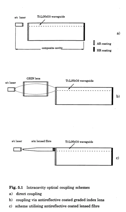
5.1.3.1 O ptical Coupling 84
5.1.3.2 A n tire fle ctive Coatings 87
5.1.3.3 M irro rs 88
5.2 E xperim ental W ork 90
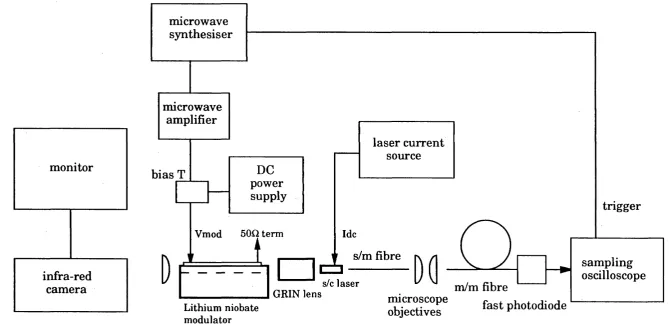
5.2.1 E xperim ental Set-Up 91
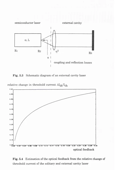
5.2.2.1 E stim ation o f the In tra c a v ity O ptical Feedback S tre n g th 93
5.2.2.2 E stim ation o f the Q u a lity o f AR C oating 94
5.2.3 M ode-Locking U tilis in g Laser C u rre n t M o d u la tio n 96
5.2.4 A M M ode-Locking E xperim ent 100
C h a p te r 6 A c tiv e M ode-Locking U sing B u lk E x te rn a l 106
C avities
6.1. E x te rn a l M irro r C onfiguration 107
6.1.1 F irs t E xperim ental C onfiguration 107
6.1.2 Second E xperim ental C onfiguration 111
6.2. E xte rn a l G ra tin g C onfiguration 115
6.2.1 In itia l Experim ents 115
6.2.2 F in a l C onfiguration 118
6.2.2.1 D escription o f the System 118
6.2.2.2 C haracterization o f the System 119
6.2.2.2.14GHz E xternal C avity 120
6.2.2.2.2 2GHz E xternal C avity 124
C hapter 7 Theory o f A ctive M ode-Locking o f S em iconductor 128
Lasers
7.1. Theory o f Active Mode-Locking 129
7.1.1 Tim e and Frequency D escriptions o f A ctive 129
M ode-Locking
7.1.2 Development o f the Theory o f Active M ode-Locking 131
o f Sem iconductor Lasers
7.2. Frequency-Dom ain F orm ulation o f A ctive M ode-Locking 133
o f Sem iconductor Lasers
7 ’2.1 A ctive Mode-Locking by C u rre n t M odulation 134
7.2.2 FM M ode-Locking 147
7.2.3 A M M ode-Locking 150
7.2.4 M odulator Effects 154
C hapter 8 N u m e rica l S im ulations o f A c tiv e M ode-Locking o f 157
M o n o lith ic E xte rn a l C a vity S em iconductor Lasers
8.1.1 G ain-S w itching o f the S o lita ry Laser 158
8.1.2 G ain-S w itching o f the E xte rn a l C a vity Laser 159
8.2 M ode-Locking by C u rre n t M odulation 163
8.2.1 N um erical S im ulations 164
8.2.2 E vo lu tio n o f M ode-Locking 169
8.2.3 D etuning o f the M odulating Frequency 169
8.2.4 V a ria tio n o f the Bias C u rre n t 174
8.2.5 V a ria tio n o f the RF C u rre n t A m p litu d e 177
8.2.6 Effects o f the L in e w id th Enhancem ent Factor 177
8.3.FM M ode-Locking 179
8.3.1 N um erical S im ulation In c lu d in g the L in e w id th 181
Enhancem ent Factor
8.3.2 N um erical S im ulation E xcluding the L in e w id th 184
Enhancem ent Factor
8.3.3 FM -Laser O peration 187
8.4. A M M ode-Locking 189
8.4.1 N um erical S im ulation In c lu d in g the L in e w id th 189
Enhancem ent Factor
8.4.2 N um erical S im ulation E xcluding the L in e w id th 192
Enhancem ent Factor
8.5 Sum m ary 192
Chapter 9
Conclusions and Future Work
195
References 202
A ppendix 1 221
lis t o f Figures and Tables
Chapter 1
Chapter 2
Fig. 2.1
Fig. 2.2
Fig. 2.3
Fig. 2.4
Schematic illu s tra tio n o f a sem iconductor laser and its 28
Fabry-Perot cavity
G ain p ro file and lo n g itu d in a l modes o f a sem iconductor 28
la se r
Schem atic diagram o f a b u ried sem iconductor laser 35
Schematic lig h t - cu rre n t curve 35
Chapter 3
Fig. 3.1 R elaxation oscillations
Fig. 3.2 G ain-sw itching o f a s o lita ry laser
Fig. 3.3 Q -sw itching o f a m onolithic external ca vity laser
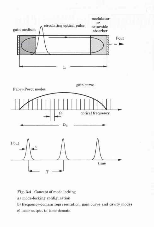
Fig. 3.4 Concept o f mode-locking
Table 3.1 Comparison between a gain-sw itched D FB and
a mode-locked ECL
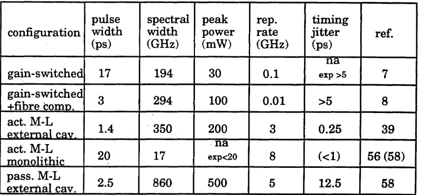
Table 3.2 State o f the a rt performance a t re p e titio n rates
below lOGHz
45
46
49
52
62
62
Chapter 4
Fig. 4.1 Electrode and waveguide com binations 68
Fig. 4.2 Standard m odulator configurations 70
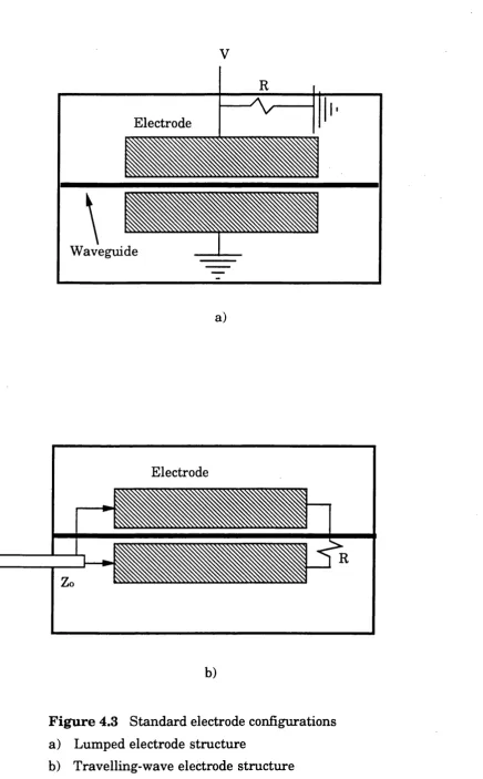
Fig. 4.3 Standard electrode structures 73
Fig. 4.4 N orm alised frequency response o f a tra v e llin g wave 76
Chapter 5
Fig. 5.1 In tra c a v ity optical coupling schemes 85
Fig. 5.2 M ode-locking experim ental arrangem ent 92
Fig. 5.3 Schematic diagram o f an external ca vity laser 95
Fig. 5.4 E stim a tio n o f the optical feedback 95
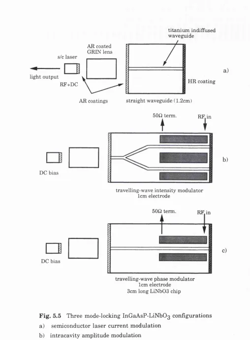
Fig. 5.5 Three InG aAsP-LiN bO g m ode-locking con fig u ra tio n s 97
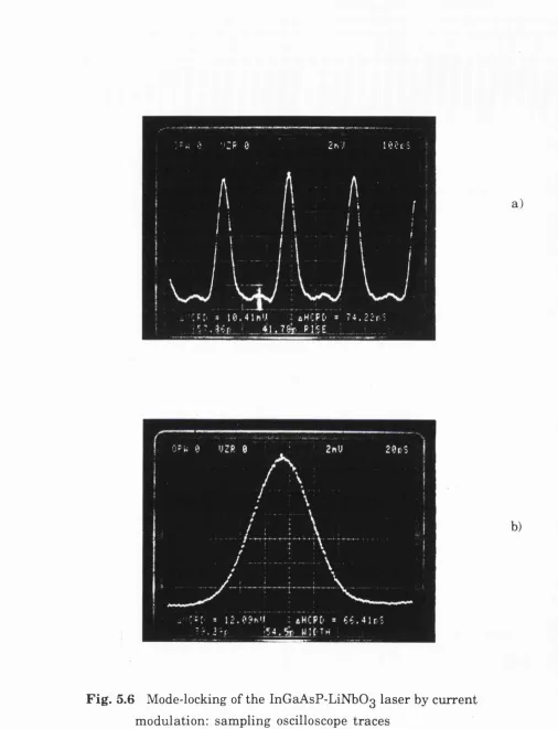
Fig. 5.6 Sam pling oscilloscope traces - cu rre n t m odulation 99
Fig. 5.7 Sam pling oscilloscope trace - in tra c a v ity loss 102
m o d u la tio n
Fig. 5.8 Sam pling oscilloscope trace - in tra c a v ity phase 104
m o d u la tio n
Chapter 6
Fig. 6.1 M ode-locking experim ental arrangem ent
Fig. 6.2 A u tocorrelation trace
Fig. 6.3 M ode-locking experim ental arrangem ent I I
Fig. 6.4 Sam pling oscilloscope / scanning FP traces
Fig. 6.5 E xperim ental arrangem ent a t N P L
Fig. 6.6 L ig h t - cu rre n t characteristics
Fig. 6.7 A utocorrelation trace - am plifie d o u tp u t
Fig. 6.8 HP lightw ave analyser traces
Fig. 6.9 Frequency detuning characteristic
Fig. 6.10 Sam pling oscilloscope trace
108
110
112 114 117 121 122 123 125 126Chapter 7
Fig. 7.1 Schematic diagram s o f the m odelled m o n o lith ic
external cavity lasers
Fig. 7.2 In tra c a v ity m odulation efficiencies fo r a lum ped
and travelling-w ave m odulator
135
C hapter 8
Fig. 8.1 G ain-sw itching o f the so lita ry laser a t 1 GHz 160
Fig. 8.2 G ain-sw itching o f the m onolithic E C L a t IG H z 161
Fig. 8.3 G m n-sw itching o f the m o nolithic EC L a t lOGHz 162
Fig. 8.4 M ode-locking by cu rre n t m odulation 166
Fig. 8.5 E volution o f inode-locking 170
Fig. 8.6 D etuning o f the m odulating frequency 172
Fig. 8.7 'Sideband flip p in g ' effect 175
Fig. 8.8 V a ria tio n o f the bias cu rre n t 176
Fig. 8.9 V a ria tio n o f the RF cu rre n t am plitude 178
Fig. 8.10 Effects o f the lin e w id th enhancement factor 180
Fig. 8.11 FM mode-locking w ith Pg=5 182
Fig. 8.12 FM mode-locking w ith pg=0 185
Fig. 8.13 FM -laser operation 188
Fig. 8.14 A M m ode-locking w ith P^=5 190
Fig. 8.15 A M mode-locking w ith Pg=0 193
List of Symbols
Sem iconductor Laser
electric fie ld vector
co n d u ctivity o f the m edium a
vacuum p e rm ittiv ity Eq
speed o f lig h t in vacuum c
induced e le ctric p o la risa tio n fP
complex envelope o f the fie ld E
complex envelope o f the polarisation P
optical a n g u la r frequency co
optical frequency v
vacuum w avelength X
vacuum wave num ber
s u sce p tib ility o f the m edium %
s u s c e p tib ility in absence o f pum ping Xo
s u s c e p tib ility due to external pum ping %p
complex d ie le ctric constant e
complex propagation constant P
complex index o f re fra ctio n p
refi*active index o f the m edium p
background re fra ctive index \i^
re fra ctive index co n trib u tio n due to pum ping App
n e t gain coefficient g
net absorption coefficient a
confinem ent fa cto r T
m irro r re fle c tiv ity R
m irro r loss
in te rn a l loss
le n g th o f the laser L
ca vity resonance frequency Vj
lo n g itu d in a l mode spacing Ü
g ain coefficient a
c a rrie r density n
c a rrie r de n sity fo r transparency 1^0
constant (App) b
lin e w id th enhancem ent factor Pc
c a rrie r d iffu s io n D
c u rre n t density J
charge o f electron Qe
laser active area volum e V
thickness o f the active area d
w id th o f the active area w
to ta l recom bination rate R (n)
n o n -ra d ia tive recom bination factor ^ n r
ra d ia tiv e recom bination factor B
A uger recom bination factor C
photon density ^ p h
stim u la te d recom bination rate ^ s t
complex envelope o f the fie ld E
lo n g itu d in a l ca vity resonance ^ 0
gain constant G
loss constant Y
photon life tim e
envelope o f the fie ld (real) A
phase o f the fie ld *
photon num ber P
average ra te o f spontaneous emission ^ s p
o u tp u t power ^ o u t
c a rrie r num ber N
c u rre n t I
c a rrie r recom bination rate Ye
spontaneous c a rrie r life tim e '^e
E xte rn a l C a vity Laser
lin e w id th o f a single-mode laser ^^'sol
lin e w id th o f an external cavity laser ^^'ext
le n g th o f a s o lita ry laser Ll
length o f the cavity L
single-pass optical coupling efficiency ti
th re sh o ld c u rre n t
re fle c tiv ity o f AR coating
external re fle c tiv ity R ^^
m o d u la tin g frequency f
bias c u rre n t ly
RF power
M ode-Locking
complex am plitude o f the mode E[
mode am plitude (real)
photon num ber Pj
phase o f the mode ^
la sin g a n g u la r frequency cOq
m o d u la tin g angular frequency
lo n g itu d in a l mode spacing A
lo n g itu d in a l ca vity resonances Q j
central Fabry-P erot frequency Ag
la te ra l mode d is trib u tio n Ç
transverse mode d is trib u tio n Ç
s p a tia lly averaged d ielectric constant (e)
mode index \i
mode absorption index a
DC component o f the c a rrie r num ber Ny
F o u rie r component o f the c a rrie r num ber
coupling loss coefficient
length o f the cavity L
le n g th o f the lasing area
le n g th o f the m odulator L j^
m odified d is trib u te d m irro r loss yin
coupling coefficient Aq
c u rre n t I
m odified gain expression G ’
s e lf sa tu ra tio n , cross sa tu ra tio n coefficients Pgj
average ra te o f spontaneous em ission R^p
fi*equency s h ift due to the average rate o)gp
o f spontaneous em ission
phase m odulator co n trib u tio n to e
re fi'a ctive index p e rtu rb a tio n A p ^
m odulation depth o f the phase m odulator
F M coupling coefficient Apj^
am plitude m odulator co n trib u tio n to e
loss p e rtu rb a tio n due to m odulation
coupling loss A M ^AMO
coupling coefficient A M A ^j^
sp a tia l v a ria tio n o f the m odulating signal 6 ^
distance from the m irro r Zq
in tra c a v ity m odulating efficiency (m odulus)
in tra c a v ity m odulating efficiency (phase) \|/
L ith iu m N iobate M odulators
o rd in a ry index
e x tra o rd in a ry index p^
change o f the o rd in a ry index Ap^
change o f the e xtra o rd in a ry index Ap
electro-optic coefficients r^
applied fie ld E
d riv in g voltage
interelectrode gap Ç
overlap between el. fie ld and opt. mode
in te ra c tio n le n g th
induced phase s h ift
o u tp u t in te n s ity
m axim um lig h t in te n s ity (in phase) lout(max)
phase s h ift difference Aq>
d ire ctio n a l coupler fa cto r p
difference in eff. prop, constants Ap
e le ctrical ban d w id th A f
electrode resistance
electrode capacitance C
Chapter 1
Introduction
The fie ld o f sh o rt o p tica l pulse generation using sem iconductor lasers
was created in the la te sixties and e a rly seventies to e x p lo it th e m a in
advantages o f the sem iconductor m edium nam ely sm a ll size, e le c tric a l
pum ping and p o te n tia l fo r in te g ra tio n w ith other o p tica l and electronic
components. In the la te seventies, when re lia b le operation o f several laser
s tru c tu re s was achieved, the fie ld received a sudden im p e tu s b y the
d e m o n stra tio n o f active m ode-locking and g a in -s w itc h in g re s u ltin g in
opticEil pulses shorter th a n 20ps. Since then, considerable e ffo rt has been
directed tow ards short pulse generation using techniques o f m ode-locking
and ga in s w itch in g . U n til the end o f th e e ig h tie s , advances w ere
re s tric te d to im proved la se r s tru c tu re s (lo w p a ra s itic s s tru c tu re s ,
d is trib u te d feedback lasers and m u ltip le quantum w e ll devices) ra th e r
th a n ra d ica l im provem ent in the techniques o f sh o rt pulse generation.
The second m ajor development in the fie ld was made in the la te eighties
by the in tro d u c tio n o f fib re am plifiers. I t was realised th a t sem iconductor
la se r diodes can serve as o p tica l pulse generators in fu tu re so li ton
system s and also p la y a d o m ina n t ro le in o p tic a l p u m p in g o f fib re
a m p lifie rs. The concept o f short pulse generation was enriched because o f
th e in c lu s io n o f self-phase m o d u la tio n and disp e rsion in to p ra c tic a l
systems w h ich consist o f laser diodes, fib re a m p lifie rs and dispersion
shifted fibres.
The consequence o f th e s o lito n system race was th a t th e la rg e s t
te lecom m unication research in s titu te s (A T T & B e ll, N T T , B T R L ) have
c o n c e n tra te d on g e n e ra tio n o f tra n s fo rm lim ite d p u lse s u s in g
sem iconductor lasers. In itia l a ctivitie s were aim ed a t active m ode-locking
u s in g b u lk or h y b rid ca vitie s or a lte rn a tiv e ly a t g a in -s w itc h in g in
m o n o lith ic lasers u tilis in g concepts o f active and h y b rid m ode-locking, as
the in te g ra tio n o f lasers, waveguides and Bragg filte rs was already in an
advanced state because o f the w ork directed tow ards n a rro w lin e w id th
sources and frequency tunable lasers. A t present, the w o rk on active
m ode-locking o f m o n o lith ic lasers seems to be directed tow ards longer
stru ctu re s ( 5-10 GHz ro u n d -trip frequencies), high-frequency m odulation
c a p a b ility o f the laser section and the o p tim isatio n o f the Bragg section
R egarding passive and h yb rid m ode-locking the e ffo rt is concentrated on
the design o f saturable absorbers in m u ltip le quantum w e ll stru ctu re s^.
C o llid in g pulse m ode-locking has also been dem onstrated in m o n o lith ic
configurations and i t resulted in sub-picosecond optical pulses^.
The m a in disadvantage o f mode-locked sem iconductor lasers is th e ir
m oderate o u tp u t power. The power levels can be increased by the use o f
e x te rn a l sem iconductor lasers a m p lifie rs or fib re a m p lifie rs . A n
a lte rn a tiv e approach to increasing the o ptical power o f the m ode-locked
sem iconductor laser is the use o f a v e rtic a l ca vity sem iconductor laser
in ste a d o f edge-em itting laser stru ctu re . The o p tic a lly pum ped v e rtic a l
c a v ity sem iconductor lasers in an e x te rn a l c a v ity c o n fig u ra tio n can
produce sub-picosecond o p tic a l pulses. M oreover, a d d itio n a l pulse
s h o rte n in g can th e n be achieved u sin g sta n d a rd pulse com pression
techniques and m u ltip le fib re a m p lifie r stages. In th is m anner pulses o f
15fs a t optical w avelength o f 1.5pm have been produced and they represent
the shortest pulses achieved u tilis in g a sem iconductor laser m edium ^.
Picosecond o ptical pulses produced by m ode-locking o f va rio u s types o f
la s e r system s have fo und a p p lic a tio n s in th e s tu d y o f u ltra fa s t
phenomena in physics, chem istry and biology. The sm all size, low power
re qu ire m en t and ease o f use o f gain switched and m o n o lith ic mode-locked
sem iconductor lasers allows the p o s s ib ility o f applications th a t w ould not
be p ra ctica l using other laser systems. A c tiv e ly mode-locked lasers have
b e tte r phase noise performance than gain-sw itched lasers and th a t w ould
One o f the m ost p rom isin g applications o f m ode-locked sem iconductor
lasers is fo r high-speed tim e d iv isio n m u ltip le x e d telecom m unications
system s^. On the tra n s m ittin g end, a mode-locked sem iconductor laser is
used as a source o f n e a rly tra n s fo rm -lim ite d o p tica l pulses fo r so lito n
generation. The outputs o f several o f these mode-locked lasers can th e n be
interleaved to form a very high data rate channel w ith ve ry sm all am ount
o f tim in g jitte r . M oreover, th e re is the p o te n tia l o f in te g ra tin g the
m odulator and the optical pulse source on the same chip. A t the receiving
end, m ode-locked lasers can be used to d e m u ltip le x th e received data
stream using four-wave m ixin g effects in optical fib re s^ or in conjunction
w ith n o n lin e a r loop m irro r sv d tc h in g ^ .
M ode-locked sem iconductor lasers have also found ap p lica tio n s in opto
e le ctro n ic m easurem ent systems. These a p p lica tio n s in clu d e im p u lse
response te s tin g o f photodiodes, h ig h re s o lu tio n o p tic a l tim e -d o m a in
in te rfe ro m e try and electro-optic sam pling o f electronic signals®.
The project described in th is thesis was proposed in 1987 and i t sta rte d in
1988. The project was funded by N ational Physical Laboratory, Teddington
and our objective was to generate lOps optical pulses fo r the ca lib ra tio n o f
fa s t photodetectors. The proposed m ethod was active m ode-locking o f a
com posite c a v ity In G a A sP -L iN b O g la s e r u tilis in g an in tra c a v ity
m o d u la to r and the p ro je ct was e n title d 'M ode-Locked L a se r u sin g
In te g ra te d O ptics'. T his approach was in itia lly adopted because a t th a t
tim e U C L had fa b rica tio n fa c ilitie s fo r lith iu m niobate waveguide devices
and fa st sem iconductor lasers were not com m ercially available.
In the ja rg o n o f mode-locking the proposed project could be called A M and
FM m ode-locking o f the composite ca vity sem iconductor lasers (A M refers
to in tra c a v ity a m p litu d e m o d u la tio n , F M to in tr a c a v ity phase
m o d u la tio n ). The th e o ry o f A M and F M m o d e -lo c k in g o f th e
inhom ogeneously and hom ogeneously broadened la se rs w ith lo n g
re la x a tio n tim es was fo rm u la te d in th e la te s ix tie s , fo llo w in g the
W hen we started th is project there was no reported dem onstration o f FM
mode lo ckin g o f sem iconductor lasers. The best exam ple o f A M mode-
lo ckin g was a tw in-section AlG aAs diode laser w ith in an e xte rn a l ca vity
in co rp o ra tin g a b u lk g ra tin g generating 8ps pulses^. The oth e r reported
co n fig u ra tio n , on w hich our project proposal was based was a composite
c a v ity In G a A sP -L iN b O g la se r in c o rp o ra tin g a h ig h speed d ire c tio n a l
coupler sw itch , w h ich produced 22ps pulses The state o f the a rt o f
active m ode-locking by c u rre n t m o du la tio n was a fa s t InG aA sP la se r
w ith in a b u lk external ca vity producing m u ltip le subpicosecond pulses a t
the re p e titio n rate o f Ib G H z ^ .
In th e fir s t and second year o f the p ro je ct we concentrated on th e
experim ental w ork : setting up a b u lk external ca vity laser, fa b ric a tio n o f
tita n iu m in d iffu s e d lith iu m niobate waveguides and the fa b ric a tio n o f
both in te n s ity and phase m odulators. A t the beginning o f the th ird year
(Septem ber 1990) we had dem onstrated sh o rt pulse generation by both
in tra c a v ity in te n s ity and phase m odulation (pulses o f the order o f 45-50 ps)
and by m ode-locking o f a composite InG aAsP - LiN bO g laser by c u rre n t
m odulation (pulses in the range o f 30-35 ps). W ith the same laser, used in
a b u lk e xte rn a l ca vity, in co rp o ra tin g a plane m irro r we produced 27ps
pulses a t a m uch low er bias current. A t th a t tim e we made a decision to
stop fu rth e r fa b rica tio n o f lith iu m niobate m odulators and assemble an
e xternal g ra tin g laser in order to fu lfil our research contract. We planned
to use the re m a in in g tim e in order to develop a n u m e rica l m odel th a t
w ould u n ite our experim ental attem pts. U ltim a te ly , we concluded our
experim ental w ork by generating optical pulses shorter th a n 10 ps using
an external g ra tin g laser followed by a sem iconductor laser a m p lifie r. In
o u r th e o re tic a l in v e s tig a tio n , we perform ed n u m e rica l s im u la tio n s o f
a ctive m ode-locking o f m o n o lith ic e x te rn a l c a v ity lasers by c u rre n t,
a m plitud e and phase m odulation. The model was based on a frequency-
dom ain fo rm u la tio n using m ulti-m ode fie ld equations.
Because o f th e broad scope o f the m a te ria l presented in th is thesis,
C hapters 2, 3, and 4 are in tro d u cto ry in th e ir character.
The basic th e o ry concerning a sem iconductor la s e r is presented in
C hapter 2. The classical description o f the laser fie ld in conjunction w ith
the phenom enological gain model is given. E m ission ch a ra cte ristics o f a
sem iconductor laser are o u tlined. The ra te equations fo r the la se r fie ld
and c a rrie r population are introduced. F in a lly , the optical feedback effects
and the external ca vity operation o f a sem iconductor laser are discussed.
G eneral m ethods fo r sh o rt o p tica l pulse generation in sem iconductor
lasers are o u tlin e d in the fir s t section o f the C hapter 3. In th e second
section, the experim ental re su lts re la te d to d iffe re n t m ethods o f pulse
gen e ra tio n are review ed, w ith the em phasis placed on a ctive mode-
locking. In the la s t section, a b rie f discussion on short pulse generation is
presented.
A n in tro d u ctio n to integrated optic lith iu m niobate m odulators is given in
C h a p te r 4. W aveguides, the e le ctro -o p tic effect, d iffe re n t m o d u la to r
configurations and high-frequency design requirem ents are discussed.
The p o s s ib ilitie s o f co m p o site -ca vity In G a A sP -L iN b O g lasers are
discussed in C hapter 5. The technical requirem ents o f com posite-cavity
lasers such as optical coupling, a n tire fle c tiv e coatings, and m irro rs , are
considered. E xperim ental results on short o ptical pulse generation using
d iffe re n t m ode-locking configurations are presented in the second section
o f the chapter. O ur experim ents have included m o d u la tio n o f th e laser
cu rre n t as w ell as in tra c a v ity in te n s ity and phase m odulation.
O u r e xp e rim e n ta l w o rk concerning a ctive m ode-locking u s in g b u lk
e x te rn a l c a v itie s is presented in C h a p te r 6. The e x te rn a l m irro r
c o n fig u ra tio n s w ere te ste d a t U C L , w h ile th e m ore com plete
m easurem ents o f the exte rn a l g ra tin g laser follow ed by a sem iconductor
Tim e-dom ain and frequency-dom ain theories o f active m ode-locking are
exam ined in the fir s t section o f C hapter 7. This is follow ed by a review o f
the th e o ry o f active m ode-locking o f sem iconductor lasers. In th e second
section o f C hapter 7, the frequency-dom ain fo rm u la tio n o f active mode-
lo ckin g o f m o n o lith ic sem iconductor lasers is derived. We obtained three
s im ila r sets o f equations fo r m ode-locking by cu rre n t m odulation, A M and
F M m ode-locking. C hapter 7 is concluded w ith a com m ent on the
in tra c a v ity m o d u la tio n e ffic ie n c y o f lum ped and tra v e llin g -w a v e
m odulators.
N u m e rica l sim u la tio n s o f g a in -sw itch in g o f a s o lita ry and m o n o lith ic
e xte rn a l c a v ity sem iconductor laser are presented in the fir s t section o f
C hapter 8. The aim was to illu s tra te the behaviour o f the averaged, single
mode ra te equations. In the second section, th e re s u lts o f n u m e rica l
sim u la tio ns o f active m ode-locking by cu rre n t m o du la tio n are presented.
We have in ve stig a te d the evo lu tio n o f m ode-locking, d e tu n in g o f the
m odulating frequency, va ria tion s o f the bias and RF drive, and role o f the
lin e w id th enhancem ent factor. The results obtained fo r FM m ode-locking
presented in the th ird section o f the chapter, show tw o d is tin c t types o f
behaviour. F M -laser operation is also dem onstrated in o u r n u m e rica l
m odel fo r F M m ode-locking. F in a lly , a set o f sim u la tio n s o f A M mode-
locking is presented.
C onclusions fro m the w o rk as a w hole are described in C h a p te r 9,
Chapter 2
Sem iconductor Laser
Since the fir s t dem onstration o f la sin g in a sem iconductor m edium in
1962, th e re has been enormous progress in b o th the th e o ry and the
m anufacture o f sem iconductor lasers optim ised fo r d iffe re n t applications.
U sing d iffe re n t sem iconductor m aterials, la sin g has been achieved over a
v e ry broad range o f frequencies, from near u ltra v io le t to fa r in fra re d .
N um erous books have been w ritte n on the subject o f sem iconductor
lasers. The standard textbooks date fro m the la te seventies and e a rly
e i g h t i e s a n d deal w ith basic device physics. M ore recent books are
concerned w ith more specific topic such as long w avelength lasers^»^,
m odulation and noise® and single-frequency structures^.
In th is thesis the in tro d u ctio n to sem iconductor lasers w ill be presented
fro m the p o in t o f view o f laser user, ra th e r th a n th e la se r designer.
M oreover, the em phasis w ill be placed on tim e-dependent phenom ena,
w hich are p e rtin e n t to gain-sw itching and m ode-locking. The lasers used
in th is p ro je c t belong to the class o f devices designed fo r o p tic a l
com m unications systems - 1.55pm index-guiding (buried h e te ro stru ctu re )
InG aAsP lasers. The basic th eoretical fo rm u la tio n and n o ta tio n th a t we
adopt are th a t o f Agraw al's textbook^ on long w avelength sem iconductor
lasers.
The m ajor p a rt o f th is chapter (Section 2.1) is devoted to basic th e o ry o f
se m ico n d u cto r la se rs in tro d u c in g th e c la ssica l fie ld d e s c rip tio n ,
th re sh o ld condition, lo n g itu d in a l modes, gain and s tim u la te d em ission,
w aveguide modes, and the em ission ch a ra cte ristics. S ection 2.2 deals
w ith the single-mode rate equations and includes the d e fin itio n o f several
im p o rta n t e n titie s . In the fin a l section o f th is chapter the concept o f
2.1 Basic Concepts
In sem iconductor lasers a sem iconductor m a te ria l is e le c tric a lly pum ped
using a forw ard-biased p-n diode stru ctu re . Charge ca rrie rs, w h ich are
in je cte d in to a th in active la ye r, provide the necessary gain a t o p tica l
frequencies. A re so n a to r form ed by the tw o cleaved facets o f th e
sem iconductor gain m edium can produce a s u ffic ie n t am ount o f o p tica l
feedback. The s tre n g th o f the pum ping o f a sem iconductor la se r is
determ ined by the injected cu rre n t density. The th re sh o ld co n d itio n fo r
the b u ild -u p o f laser o scilla tio n is reached when the gain overcomes the
to ta l ca vity loss. A ny fu rth e r increase in injected c u rre n t density above its
th re s h o ld value leads to la se r ra d ia tio n d o m ina te d b y s tim u la te d
em ission.
In th is section, our in te n tio n is to provide a b rie f d e scrip tio n o f th e
elem entary concepts related to understanding o f the sem iconductor la se r
dynam ics and m ode-locking. We s ta rt w ith the classical fie ld description.
2.1.1 C lassical F ield D escription
The classical description o f optical phenomena is based upon M a xw e ll’s
equations. The p ropagation o f an electrom agnetic wave th ro u g h an
atom ic m edium is described by the wave equation. The a im o f th is
subsection is to introduce the wave equation and optical param eters such
as the d ie le c tric constant, the re fra c tiv e in d e x and th e a b so rp tio n
coefficient w hich determ ine the propagation characteristics..
S ta rtin g fro m M axw ell’s equations a wave equation o f the fo llo w in g form
can be derived:
v Ç - - 5 - — - — = (2.1)
In th is equation *E and T represent the e lectric fie ld vector and induced electric p o la risatio n vector respectively; Eq is the vacuum p e rm ittiv ity , c is
the speed o f lig h t and o is the co n d u ctivity o f the m edium . The wave
equation (2.1) is v a lid fo r a rb itra ry tim e -va ryin g fie ld s. F o r optical fie ld s
w ith harm onic tim e v a ria tio n we w rite
S (x,y,z,t) = Re [ E (x,y,z) e 'j°*] (2.2)
fP(x,y,z,t) = Re [ P (x,y,z) e-J“ ^] (2.3)
w here co = 2tcv is the a n g u la r frequency and v = c/A, is th e o s c illa tio n
frequency o f the optical fie ld a t the vacuum w avelength X. S u b s titu tin g
Eqs. 2.2 and 2.3 in Eq. 2.1 we obtain:
V Ï + k | ( l+ j5 . ) E = - ^ p (2.4)
e<p) 6o
where kQ=co/c= IkIX is the vacuum wave num ber.
U nder steady-state conditions the response o f the m edium to the e lectric
fie ld is governed by the s u s c e p tib ility % defined by P = £oX(co)E. The
s u s c e p tib ility can be decomposed in to tw o p a rts : Xq* th e m edium
s u s c e p tib ility in the absence o f external pum ping and %p rela te d to the
s tre n g th o f pum ping. B o th Xo Xp are com plex and frequency-
dependent.
E quation 2.4 can he re -w ritte n as the tim e-independent wave equation o f
the form :
V^E + ek?E = 0 (2.5)
where we have introduced the complex d ielectric constant defined as
e = e' + je" = 1 + Xo + Xp + j ^ (2.6)
The tim e-independent wave equation can be used to o b ta in th e s p a tia l
mode stru ctu re o f the optical fie ld in a p ra ctica l device. In the sim plest
case, the plane-wave solutions o f Eq. 2.5 can be treated. The propagation
ch a ra cte ristics o f a plane wave in a m edium are u s u a lly described in
term s o f tw o optical constants, the index o f refi*action \i and the absorption
constant a. I f we consider a plane wave propagating in the z d ire ctio n
E = Eoexp(jPz) (2.7)
where Eq is the constant am plitude and the complex propagation constant
is given as
P = k j/ë = k<p (2.8)
and where p is the complex refractive index u su a lly w ritte n as
= (2.9)
A ssum ing th a t a<<|xk^ using e = p? and equating the re a l and im a g in a ry
parts, fo llo w in g relations can be obtained:
p = VF = Vl+Re(xJ+Re(%j^ (2.10)
(2.11)
2.1.2 Threshold C ondition and L o n g itu d in a l Modes
The plane wave so lu tio n o f the wave equation can be used to o b ta in an
estim ate o f the laser frequency and the optical gain requ ire d fo r the onset
o f lasing. In a sem iconductor laser o f le n g th L , shown schem atically in
Fig. 2.1, the th in ce n tra l region provides the o p tica l g ain and cleaved
facets form a Fabry-P erot cavity to provide optical feedback. The o p tica l
C u rre n t In je ctio n
A ctive Region
Cleaved Facets
R1
G ain M edium
FABRY-PEROT C A VITY
R2
F ig . 2.1 Schematic illu s tra tio n o f a sem iconductor laser and its
Fabry-Perot cavity
gain
lasing mode loss
lo n g itu d in a l modes
►
optical frequency
F ig . 2.2 G ain p ro file and lo n g itu d in a l modes o f a sem iconductor
laser. The threshold is reached when the gain o f the
the complex propagation constant can be obtained by com bining Eq. 2.8
and 2.9:
P = ^iko+j|.
(2.12)
I f Re(Xp) is sm all (Eq. 2.10), the re fra ctive index can be a p p ro xim a te ly
expressed as
p = Pb+A^ip (2.13)
where pb= Vl+Re(%() and App = ■
2|J-b
Pb is th e background in d e x o f the unpum ped m a te ria l and App is
c o n trib u tio n due to the presence o f charge ca rrie rs. A ppis negative and
a lth o u g h i t is often less th a n 1% o f pb i t s ig n ific a n tly affe cts th e
sem iconductor laser behaviour.
The a b so rp tio n co e fficie n t a has th re e c o n trib u tio n s : th e m a te ria l
absorption Im(%Q), its reduction w ith e xte rn a l pum ping Im(%p) and the
o/EqCO te rm w hich accounts fo r other in te rn a l losses such as fre e -c a rrie r
absorption and scattering. I t is often convenient to in troduce the n e t gain
g defined as
g = — Im(Xo+Xp) (2.14)
and to express the net absorption coefficient as
a = -Fg + (2.15)
In th is expression F represents the confinem ent fa c to r, w h ich is the
To o b ta in the th reshold condition, i t is re q u ire d th a t the o p tic a l fie ld
should reproduce its e lf a fte r each ro u n d -trip under steady-state condition.
The threshold condition is:
Y R % e W = i (2.16)
E q u a tin g the re a l and im a g in a ry p a rts o f Eq. 2.16 and using Eq. 2.12
fo llo w in g expressions can be obtained:
Y R ^ e - “ L = l (2.17)
sin(2|ikJL<) = 0 (2.18)
The fir s t expression (Eq. 2.17) gives the threshold gain. I t can be w ritte n
in the form :
+ “ in t (2.19)
where represents the m irro r loss expressed as
The physical m eaning o f the threshold gain equation (Eq. 2.19) is th a t the
gain due to external pum ping m ust balance the to ta l losses. The effect o f
spontaneous em ission has been ignored in th is sim ple analysis.
The im a g in a ry p a rt o f the threshold equation (Eq. 2.18) can be used to
obtain the lasing frequency. Eq. 2.18 has m u ltip le solutions o f the form
2 p k o L = 2i7c ( 2 . 2 1 )
where i is an integer. U sing kQ=27cv/c, the lasing frequency v is
v = V i = ^ (2.22)
The la s e r tends to o scilla te a t a frequency th a t coincides w ith a
lo n g itu d in a l mode supported by the FP cavity. In the case o f homogeneous
broadening only one lo n g itu d in a l mode, whose frequency n e a rly coincides
w ith th e peak gain, reaches th re sh o ld (F ig. 2.2) and the la s e r also
rem ains single-moded above threshold.
In a sem iconductor laser, the re fra ctive index p va rie s w ith frequency,
and the lo n g itu d in a l mode spacing Q is given as
(2.23) 2ngL
where |Xg = n + represents the group refractive index.
2.1.3 G ain and S tim ulated Em ission
In sem iclassical la se r theory the m edium response is governed b y the
p o la riz a tio n induced by the optical fie ld and leads to a s u s c e p tib ility %
defined by the expression P = eo%(co)E. The induced p o la riza tio n is given in
te rm s o f d e n s ity -m a trix and dipole-m om ent o p e ra to rs. The decay
m echanism s include in tra b a n d processes th a t occur a t a tim e scale o f
-O .lp s and in te rb a n d processes a t a tim e scale o f few ns. In tra b a n d
processes are electron-electron scattering and electron-phonon sca tte rin g
w h ile in te rb a n d processes include ra d ia tiv e recom bination (spontaneous
and s tim u la te d em ission) and n o n ra d ia tiv e re c o m b in a tio n (A u g e r
process). The a n a lysis o f a sem iconductor la s e r u s in g a rig o ro u s
sem iclassical approach is very complex.
A phenomenological approach, w hich is based on the observation th a t the
g a in is a lm o st a lin e a r fu n c tio n o f th e in je c te d c a rrie r d e n s ity , is
g e n e ra lly used fo r describing a sem iconductor laser. Therefore, th e gain
g(n) = a(n-ng) (2.24)
w here a is the gain coefficient and n^ is the c a rrie r d e n sity re q u ire d to
achieve transparency (an^ is the absorption coefficient o f the unpum ped
m a te ria l). The re fra ctive index is also assumed to v a ry lin e a rly w ith the
c a rrie r density
A|Xp=bn (2.25).
where b = ^ and is often determ ined experim entally
on
C om paring the Eqs. 2.24 and 2.25 to the Eqs. 2.13 and 2.14 i t can be seen
th a t the v a ria tio n o f the complex su sce p tib ility Xp is also a lin e a r fu n ctio n
o f the c a rrie r density
X p = ^ b |2 b - j^ n (2.26)
A ve ry im p o rta n t param eter fo r the sem iconductor la se r m o d e llin g is
defined as:
Im(Xp) (2.27)
9n
\9n/
and i t is called th e lin e w id th enhancem ent fa c to r o r a n tig u id in g
p a ra m e te r.
The c a rrie r density n is related to the pum p param eter, c u rre n t de n sity J,
th ro u g h the rate equation th a t incorporates a ll the m echanism s by w hich
the ca rrie rs are generated and a n n ih ila te d inside the active region:
^ = D ( V n ) + - i- - R ( n ) (2.28)
In the c a rrie r density ra te equation (Eq. 2.28) the fir s t te rm accounts fo r
c a rrie r d iffu s io n and D is the d iffu s io n co e fficie n t. The second te rm
describes e x te rn a l p u m p in g w h ich is in v e rs e ly p ro p o rtio n a l to the
m agnitude o f the electron charge q@ and the active la ye r thickness d. The
la s t te rm , R (n), represents th e c a rrie r loss due to ra d ia tiv e and
n o n ra d ia tive recom bination.
In the case o f stro n g ly index-g u id in g lasers the d iffu s io n te rm can be
neglected because the dim ensions o f the active region are often sm all
com pared to the d iffu s io n length. In th is case the steady-state can be
w ritte n as
J = qedR(n) (2.29)
The c a rrie r recom bination rate is often expressed expressed as
R(n) = A j^ n + B n^ + Cn^ + R gtN p^ (2.30)
The fir s t te rm represents n o n -ra d ia tiv e re co m b in a tio n such as the
recom bination a t defects. The quadratic te rm B n^ is due to spontaneous
ra d ia tiv e re c o m b in a tio n . The cubic te rm C n ^ is due to A uger
re co m b in a tio n and i t is p a rtic u la rly im p o rta n t fo r lo n g -w a ve le n g th
lasers. The la s t te rm R g t^ p h is due to stim u la te d recom bination w hich
leads to lasing action and i t is proportional to the photon density N p ^ w ith
the net rate
R s t = -^ g ( n ) ■ (2.31)
2.1.4 W aveguide Modes
The lig h t e m itte d by a sem iconductor la s e r has fin ite tra n sve rse
dim ensions because i t o rig in ate s from th e th in active re gion , w h ich
provides the gain via stim ulated emission. The o u tp u t is in the fo rm o f a
the beam is dependent on the laser structure.
In h e te ro s tru c tu re sem iconductor lasers the fie ld confinem ent in the
transverse d irection, perpendicular to the ju n c tio n plane, occurs th ro u g h
d ie le ctric w aveguiding due to the re fra ctive index d is c o n tin u ity between
the active and cladding layers. F ield confinem ent in the la te ra l d ire ctio n ,
p a ra lle l to the ju n c tio n plane depends on the la se r s tru c tu re . In gain-
guided lasers, the v a ria tio n o f the optical gain (due to c a rrie r d iffu s io n )
confines the optical mode. Index-guiding lasers have a b u ilt-in re fra ctive
index step th a t confines the mode. A schematic cross-section o f a b u rie d
h e te ro s tru c tu re laser, w hich is a ty p ic a l exam ple o f a s tro n g ly in d e x
g u id in g la se r, is shown in F ig . 2.3. Besides p ro v id in g th e o p tic a l
confinem ent, the buried heterostructure laser incorporates p-n-p blocking
structures w hich create the cu rre n t confinem ent.
The m ost common m ethod fo r so lvin g tra n sve rse and la te ra l fie ld
d is trib u tio n s o f an index guided sem iconductor laser is the effective index
m ethod. Instead o f solving the tim e-independent tw o-dim ensional wave
equation (Eq. 2.5), the problem is s p lit in to tw o one-dim ensional p a rts
whose solutions are re la tiv e ly easy to obtain. The effects o f gain and loss
are tre a te d as p e rtu rb a tio ns o f the lossless case. The mode propagation
constant is given by
P = ^ o + j | (2.32)
w here |i and a represent the re fra c tiv e in d e x and th e a b so rp tio n
coefficient o f the mode supported by re cta n g u la r waveguide o f w id th w
and thickness d.
2.1.5 Em ission C haracteristics
E m ission c h a ra cte ristics used to characterise th e perform ance o f a
sem iconductor laser are the lig h t-c u rre n t, spatial-m ode, sp e ctra l and
p - InGaAsP
n - In P p - InP
n - InP
InGaAsP active area
p - In P p - InP
n - InP
n - InP Substrate
F ig . 2.3 Schematic diagram o f a buried heterostructure laser. The
re fra ctive index d isco n tin u ity between the active and cladding layers is
p ro vid in g mode confinem ent through the to ta l in te rn a l re flectio n .
power saturation
lineair regime
5
th re sh o l
C u rre n t (mA)
F ig . 2.4 Schematic lig h t-c u rre n t curve o f a buried hete ro stru ctu re
laser. C h a racte ristic regions are threshold, lin e a r region and pow er
T yp ica l lig h t-c u rre n t ch a ra cte ristic o f an index-guided long-w avelength
la se r is shown in F ig 2.4. Three regions o f the lig h t-c u rre n t curve
correspond to below th re sh o ld o p e ra tio n dom inated b y spontaneous
em ission, lin e a r a b ove-threshold re g io n d o m in a te d b y s tim u la te d
em ission and the power sa tu ra tio n region. The o u tp u t power s a tu ra tio n
can be caused by the increase o f leakage currents, A uger recom bination
and in te rn a l loss. The slope o f dP Q ^^/dl is a m easure o f th e device
efficiency.
The dim ensions o f the e llip tic a l spot and its divergence angles, both
p a ra lle l and p e rp e n d icu la r to the ju n c tio n plane, are im p o rta n t beam
param eters associated w ith the laser mode. In the case o f th e index-
guided laser the near fie ld d is trib u tio n can be expressed as a G aussian,
and from th is the fa r-fie ld p a tte rn can be easily obtained. The s itu a tio n is
more com plicated fo r n a rro w -strip e gain-guided lasers where the la te ra l
fa r fie ld takes the form o f a tw in-lobe pattern.
In o p tic a l co m m u n ica tio n a p p lic a tio n s , th e pow er sp e ctru m o f a
sem iconductor la se r is an im p o rta n t device c h a ra c te ris tic . B elow
th re sh o ld , the o u tp u t is determ ined b y spontaneous em ission w ith a
spectrum o f the order o f 30nm. Above threshold, the lo n g itu d in a l mode
closest to the gain peak increases in power, w h ile th e pow er in th e
re m a in in g side peaks saturates. The gain p ro file o f th e sem iconductor
la s e r is hom ogeneously broadened and the m u lti-m o d e b e h a vio u r is
a ttrib u te d to spatial-hole b u rning, spectral-hole b u rn in g and a h ig h ra te
o f spontaneous em ission e n tering the laser mode. A p a ram eter used to
describe the spectral p u rity o f a sem iconductor la s e r is th e mode-
suppression ra tio (MSR). MSR is defined as a ra tio o f the m ain-m ode
pow er to the power ca rrie d by the m ost intense side mode. F o r some
o p tica l com m unication applications, MSRs in excess o f 20dB are needed,
and they can be achieved w ith distributed-feedback sem iconductor laser
configurations. A nother q u a n tity o f p ractica l in te re s t is the spectral w id th
flu c tu a tio n s associated w ith the process o f spontaneous em ission.
S pectral lin e w id th is ty p ic a lly o f the order o f lOOMHz and is in v e rs e ly
prop o rtio n a l to the laser power.
In m any applications, p a rtic u la rly in optical fib re com m unications, the
device c u rre n t is m odulated p e rio d ica lly and the la se r o u tp u t takes a
pulsed form . The laser responses to a step increase o f c u rre n t w ith a
tu m -o n delay o f few nanoseconds, follow ed by the ra p id increase in laser
power and oscillations o f several nanoseconds before a tta in in g a steady-
state value. The frequency o f re la xa tio n oscilla tio n s is governed by the
n o n lin e a r dynam ics o f the p h o to n -ca rrie r in te ra c tio n s . The re la x a tio n
o s c illa tio n frequency is ty p ic a lly in the low er GHz range and increases
w ith an increase o f the laser output power.
U nder high-frequency d ire ct m odulation, the spectral side modes are
considerably enhanced compared to those in the CW case. M oreover, the
lin e w id th o f an in d iv id u a l lo n g itu d in a l mode increases. The lin e
broadening is related to the carrier-induced re fra ctive index change and
leads to frequency chirping.
2.2 Rate Equations
Rate equations provide the standard way o f in v e s tig a tin g sta tic, spectral
and dynam ic characteristics o f a sem iconductor laser. In general, they
are m ulti-m ode equations, b u t in m ost cases a s in g le -lo n g itu d in a l mode
tre a tm e n t is su fficie n t. Rate equations can be fo rm u la te d e ith e r fo r the
optical fie ld , in cases when both the am plitude and phase in fo rm a tio n are
needed, or ju s t fo r the photon density or number.
The fie ld ra te equation can be derived from the wave equation u sin g the
a d iabatic approxim ation. The m eaning o f th is appro xim a tio n is th a t the
m a te ria l response is in sta n ta n e o u s, w h ich is c e rta in ly v a lid on
tim escales o f Ip s or longer. The optical fie ld can be expanded in term s o f
to e lim in a te second o rde r d e riv a tiv e s and p ro d u cts o f fir s t o rd e r
d e riv a tiv e s . T h is procedure is em ployed in C h a p te r 7 to d e rive the
equations o f m ode-locking. A fu rth e r a p p ro xim a tio n w h ich is u s u a lly
a pplied is to replace localised m irro r losses by a d is trib u te d m irro r loss.
A p p lyin g these approxim ations to the case o f a single-m ode laser, a fie ld
ra te equation can be derived as
# = j-^co - Oo)E + i(G - yXl - jPc)E (2.33)
a t |Lig It
In th is e q u a tio n E represents th e s lo w ly v a ry in g com plex mode
am plitude. Pg is is the group index corresponding to the mode index p.
is the cavity-resonance frequency and co is the la sin g frequency. Pq is the
lin e w id th enhancem ent factor. The net ra te o f s tim u la te d em ission and
photon decay rate are defined as
G=rvgg (2.34)
7 = V g (c C jj^ + C 4 j^ ^ )= l/X p ( 2 .3 5 )
where Xp represents the photon life tim e and Vg is the group velocity.
The a m p litu d e and phase ra te equations can be obtained i f th e fie ld
equation is separated in to its real and im a g in a ry p a rts using
E = Ae-j4> (2.36)
The am plitude and phase rate equations are
^ = 1 (G -y)A (2.37)
co; 2t
— - — (co - Qq) + & Pc(G - y) (2.38)
C/t Pg z
The am plitude rate equation is more often w ritte n in term s o f the photon
P = ^ l N " d V (2.39)
where hco is the photon energy and V is the volum e o f the active layer. For
the photon num ber we can w rite follow ing ra te equation
^ = ( G - Y ) A + Rsp (2.40)
at
The la s t te rm Rgp represents the ra te a t w hich spontaneously e m itte d
photons are added to the to ta l photon population. The o u tp u t power from a
facet, Pout, is related to the photon num ber P by the fo llo w in g re la tio n
Pout = ^ hcovgamP (2.41)
where v ^ a ^ represents the ra te a t w hich photons o f energy hco escape
thro u g h the tw o facets.
The c a rrie r ra te equation (Eq. 2.28) can be expressed in te rm s o f the
c a rrie r num ber inside the active layer defined as
N = I ndV = nV (2.42)
where the volum e V is V=Lw d (length x w id th x thickness). I f the effect o f
c a rrie r d iffu sio n is neglected, the ca rrie r num ber ra te equation becomes
f - i - n n - G P (2.43)
w here
Yg represents the c a rrie r recom bination ra te and is used to define the
spontaneous c a rrie r life tim e Xg.
The la s t te rm in the photon num ber ra te equation (Eq. 2.40), Rgp can he
defined as
Rsp=PspB^ (2.45)
where pgp is called the spontaneous em ission factor and B is the ra d ia tiv e
recom bination coefficient.
Equations 2.40, 2.38 and 2.43 are the single-mode ra te equations. They are
d e te rm in is tic equations because the spontaneous em ission noise is
represented by an average value. These d e te rm in is tic equations can be
used fo r studying the steady-state characteristics and tra n s ie n t behaviour
o f single-m ode or m ulti-m oded sem iconductor lasers. H ow ever, to model
spontaneous em ission effects such as in te n s ity noise and lin e w id th i t is
necessary to in clu d e stochastic noise sources in th e ra te equations.
R egarding dynam ic behaviour, spontaneous em ission also p la ys an
im p o rta n t role in m ode-locking and is the source o f tim in g jit t e r in gain-
sw itched lasers.
2.3 E xte rn a l C avity Semiconductor Laser
The behaviour o f continuous-wave and m odulated sem iconductor lasers is
affected by re fle c tio n feedback. M uch research has been devoted to
s tu d y in g b o th the m e rits and dem erits o f e xte rn a l o p tic a l feedback.
Im proved mode selection o f Fabry-Perot lasers®, lin e w id th n a rro w in g and
tu n in g ^ and reduced ch irp in g 10 can be m entioned as advantages o f the
e x te rn a l c a v ity stru ctu re s. W hereas, in a c e rta in feedback re gion , an
in s ta b ility named coherence collapse' can o c c u rH ; m oreover, tiltin g o f
em ission^^.
The operation o f a sem iconductor laser w ith an e xte rn a l re fle cto r depends
on b o th the m agnitude o f the re fle ctio n and the le n g th o f the e xte rn a l
ca vity. The CW perform ance o f a distributed-feedback la se r exposed to
re fle ctio n feedback has been classified in to five regimes
1) A t the low est levels o f feedback the laser operation is stable b u t the
am ount o f lin e n a rro w in g depends on the phase o f the re fle cte d lig h t.
L in e w id th reduction has been observed fo r a feedback level o f -80dB.
2) A t a feedback level w hich depends on the distance to the e xte rn a l
re fle cto r (-70dB fo r a 40cm cavity), mode-hopping between exte rn a l ca vity
modes has been detected.
3) In the range from -45dB to -40dB stable operation and lin e n a rro w in g
have been observed, independent o f the feedback phase.
4) F o r optical feedback levels from -40dB to -lO dB lin e w id th broadening,
by several orders o f m agnitude, has been observed. T his phenom enon is
called coherence collapse' and i t is accompanied by a la rg e increase o f
in te n s ity noise.
5) F o r strong feedback levels stable single-mode operation w ith a n arrow
lin e w id th has been observed. In th is region, the s ta b ility o f operation is not
affected by changes in the external cavity length.
G enerally, e xternal ca vity devices should be designed to operate in the
strong feedback regim e. In the case o f b u lk e xte rn a l ca vitie s an a n ti-
re fle ctive coating should be deposited on one sem iconductor laser facet in
order to im prove the coupling efficiency.
One o f th e m ost im p o rta n t c rite ria fo r sem iconductor lasers in h ig h
The lin e w id th o f a single-mode laser diode is described by the m odified
Schawlow-Townes fo rm u la ^^:
A V s o l= ^ ( l+ p / ) (2.46)
where Rgp is the average spontaneous em ission ra te in to the la sin g mode,
P is the to ta l lasing photon num ber in the sem iconductor ca vity and is
the lin e w id th enhancem ent factor. The lin e w id th o f an e xte rn a l c a v ity
laser can be expressed as^"^:
AVecl = AVsol / (1+11^^) (2.47)
L and are the optical lengths o f the external ca vity and s o lita ry laser, T)
is the effective single-pass coupling efficiency. In re a lity , the lin e w id th o f
an exte rn a l ca vity laser is inversely proportional below a ce rta in value
(-1 5 c m ) above w h ich i t reaches a s a tu ra te d va lu e . One possible
explanation o f lin e w id th saturation is the effect o f 1 /f noise
The lo n g itu d in a l mode separation in long external ca vity lasers is o f the
order o f IG H z and i t is necessary to include a frequency selective elem ent
in the ca vity in order to prevent mode-hopping. The m ost common way is
to use a g ra tin g in ste a d o f the plane m irro r. The e x te rn a l g ra tin g
c o n fig u ra tio n has the a d d itio n a l b e n e fit o f a broad tu n in g range. The
lin e w id th o f 2kH z and a coarse tu n in g o f 90nm have been reported fo r the
18cm long c a v ity^^. A more compact, fixed w avelength co n fig u ra tio n can
be form ed usin g a d istributed-feedback la se r w ith th e fibre-extended
c a v ity ^7. F or such a device the lin e w id th o f 70kHz has been reported fo r a
5.5cm c a v ity . M o n o lith ic e x te rn a l c a v ity la se rs h a v in g sub-M H z
l i n e w i d t h h a v e been dem onstrated usin g sem iconductor stru ctu re s
shorter th a n 2mm.
The th e o re tic a l a n a lysis o f e x te rn a l c a v ity sem iconductor lasers is
reported in the lite ra tu re deal w ith the case o f w eak feedback, w hich
s tric tly speaking, is n ot v a lid fo r an exte rn a l c a v ity laser. In the weak
feedback approxim ation a single re flectio n is added to the sem iconductor
laser fie ld rate-equation^^. The effects o f strong feedback can be tre a te d by
in tro d u c in g a frequency dependent am plitude re fle c tiv ity ^ ^ in to the ra te
equation fo r the laser fie ld . A nother approach is to tre a t a composite ca vity
system in w hich separate fie ld equations fo r active and passive c a v ity are