R E S E A R C H
Open Access
Improved CT algorithm based on target
block division and feature points matching
Wenhao Wang
*, Mingxin Jiang, Yunyang Yan, Xiaobing Chen and Wendong Zhao
Abstract
For compressive tracking (CT) algorithm, it is vulnerable to the occlusion, when tracking targets. An improved CT algorithm based on target division and feature point matching is proposed in this paper, which can determine different target tracking states by the method of target division. When the target is in normal tracking or partial occlusion, the target is located accurately by the sub-block with the highest discrimination degree. In this scenario, the classifier only updates the unblocked sub regions in order to avoid the error of updating the occlusion information. When the target is completely occluded or lost in some frames, ORB feature matching is used to re-locate the target. Experimental results show that our proposed CT algorithm can improve the robustness of the algorithm and reduces the drift problem.
Keywords:Target tracking, Occlusion, Sub-region, Feature points matching
1 Introduction
Target tracking has a very important application in the field of computer vision (motion analysis, intelligent monitoring,
imaging guidance, human-computer interaction). At
present, there are some robust tracking algorithms. For ex-ample, super pixel image segmentation method is intro-duced to track target in the case of occlusion and texture changes [1–3]. A tracking algorithm based on multiple stable points is proposed in [4], which have achieved good results in the tracking of non-rigid object. Although these al-gorithms are highly robust, they are quite time-consuming, which does not cater to the real-time tracking requirements. In real-time object tracking, tracking is regarded as on-line classification, which means using classifiers finds the decision boundaries to separate objects from background.
Such algorithms include online learning tracking [5],
real-time tracking based on online boosting algorithm [6], online tracking algorithm based on semi-supervised [7,8], and so on. In recent years, compression sensing theory is introduced into target tracking [9, 10]. The compressive tracking (CT) method is proposed in [10–12], which com-presses the target feature with a sparse measurement matrix and then inputs the compressed feature into the
Bayesian classifier. Candidate region with the maximum confidence is selected as target tracking region; thus, the algorithm is adaptive. As this algorithm effectively com-presses the target feature, it has better real-time perform-ance. However, there are still some defects in the algorithm. The main problems are concentrated on the following two aspects.
1. Tracking drift problem
In tracking the moving target, it tends to introduce more background content once the target is blocked. As a result, the classifier learns a lot of obstruction informa-tion instead of the real target informainforma-tion, and then, the classifier’s parameters fit more to the obstruction than to the real targets, which makes the tracking position devi-ate from the target region. In the subsequent tracking process, this offset will gradually accumulate, resulting in tracking failure [13,14].
2. Lack of judgment on occlusion
The updating of the classifier parameters of the com-pressive tracking algorithm is based on the statistical characteristics of the positive and negative samples in the current frame compression domain and the model parameters of the positive and negative samples of the * Correspondence:[email protected]
Faculty of Computer and Software Engineering, HuaiYin Institute of Technology, No. 1, at East Meicheng Road, Huai’an City 223003, Jiangsu, China
previous frame. When the target is occluded, the ex-tracted compressed feature of the target will undoubt-edly lead the samples to be incorrectly classified. In other words, if the classifier is updated on the basis of wrong positive and negative sample, it will result in a de-cline in the classification performance of the classifier [15]. Therefore, the updating process of the original al-gorithm is blind and lacks the basic decision mechanism. In addition, there is no corresponding memory mechan-ism for historical samples. Moreover, once the tracking fails, the algorithm has no retracing ability.
For overcoming the shortcomings of the compressive tracking algorithm, this paper proposes an improved method, which mainly includes two aspects:
1. The status of the target can be determined by dividing the sub-regions. When the target is in nor-mal tracking or partially occluded, the classifier only updates the unblocked sub-region to avoid the error of the classifier updating occlusion information. 2. When the target is in complete occlusion or lost,
ORiented Brief (ORB) feature matching is used to re-locate the target.
The experimental results show that the improved compressive tracking algorithm has higher robustness and real-time performance.
2 Compressive tracking methods
In [9], featureV∈Rm× 1 is extracted based on compres-sive process, which is defined as:
V¼RX ð1Þ
where X∈Rn× 1 is the signal translated from target candidate region andR∈Rm×n(m< <n)is the feature ex-traction matrix.Rcan be defined as:
ri;j¼
ffiffi
s
p
01 with probability 1with probability 1−=12=ss
−1 with probability 1=2s
8 <
: ð2Þ
wheres is produced randomly from 2 to 4. As the
di-mension ofX is very large, if the Eq. (2) is used directly, the computational cost is very high. Therefore, the target is often randomly divided into some sub-regions. Feature Vis extracted as:
vi¼
XNR
j¼1 ri;jRectsffiffiffiffiffiffiffii;j
NR
p ð3Þ
where Rects is the sub-region produced randomly from target candidate region, NR is the number of sub-regions, and ri, jis randomly selected from 1 to−1.
From Eq. (3), we can see that the compression feature is
the weighted sum of the original feature usingri,jas the
weight.
The tracking process is to find target candidate
re-gions, which has the maximum confidenceH(v).
Assum-ing that all elements in Vare independently distributed, H(v) can be defined as
H vð Þ ¼ log
Yj
i¼1
p vðijy¼1Þp yð ¼1Þ
Yj
i¼1
p vðijy¼0Þp yð ¼0Þ
¼X
j
i¼1
logp vðijy¼1Þ p vðijy¼0Þ ð4Þ
where y∈{0, 1} represents sample label, y= 1 repre-sents the positive sample (target), and y= 0 represents the negative sample (background); supposing the prior probabilities of the target and background are equal, that is to sayp(y= 1) =p(y= 0) = 1/2, the conditional distribu-tionsp(vi|y= 1) andp(vi|y= 0) are assumed to Gaussian
distribution [16]:
p vð ijy¼1Þ N u1i;δ1i
p vð ijy¼0Þ N u0i;δ
0
i
ð5Þ
where u1 and δ1respectively represent the mean and
standard deviation of the target samples; u0 and δ0 are the mean and standard deviation of the background samples, respectively. The target samples are from the region near the target, and the background samples are from the regions far from the target. At the beginning, u1
i, δ 1
i, u0i, and δ 0
i are initialized with the first frame. In the following tracking process,u1
i,δ1i,u0i, andδ0i are con-tinually updated; the method can be defined as:
u1i←λu1i þð1−λÞu1
δ1
i←
ffiffiffiffiffiffiffiffiffiffiffiffiffiffiffiffiffiffiffiffiffiffiffiffiffiffiffiffiffiffiffiffiffiffiffiffiffiffiffiffiffiffiffiffiffiffiffiffiffiffiffiffiffiffiffiffiffiffiffiffiffiffiffiffiffiffiffiffiffiffiffiffiffiffiffiffiffiffiffi λ δ1
i
2
þð1−λÞ δ1 2þλð1−λÞ u1
i−u1
2
q
u0i←λu0i þð1−λÞu0
δ0
i←
ffiffiffiffiffiffiffiffiffiffiffiffiffiffiffiffiffiffiffiffiffiffiffiffiffiffiffiffiffiffiffiffiffiffiffiffiffiffiffiffiffiffiffiffiffiffiffiffiffiffiffiffiffiffiffiffiffiffiffiffiffiffiffiffiffiffiffiffiffiffiffiffiffiffiffiffiffiffiffi λ δ0
i
2
þð1−λÞ δ0 2þλð1−λÞ u0
i−u0
2
q ð6Þ
where λ means the learning rate, the smaller λ value
is, the faster the update rate is, and the less the reserved feature information is.
3 Improved CT method
On the basis of the original CT algorithm, the occlusion discrimination mechanism and a target re-location strat-egy are introduced to improve the accuracy and adapt-ability of the algorithm in this paper.
3.1 Occlusion discrimination
In the process of target tracking, other targets and back-grounds often block tracking target. To solve this prob-lem, it is necessary to determine whether the target is obscured or not. So the target state is divided into nor-mal state and occlusion state in this paper. According to the state of the target, different processing mechanisms are used respectively.
In the CT algorithm, the confidenceH(v) of all candi-date target regions is obtained by Eq. (4), and we select
the region with the maximum confidence max(H(v)) as
the target region. From Eq. (4), we can know that the
value of H(v) is determined by (p(vi|y= 1)/p(vi|y=
0)).The more features of the target in the candidate re-gion are close to the target, the more likely the candidate region is the target.
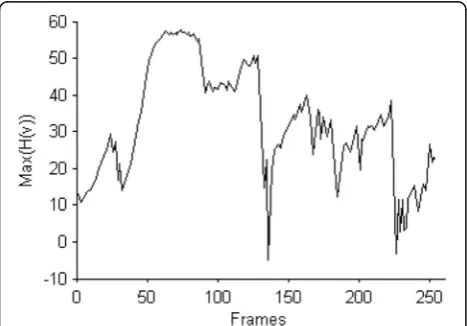
H(v) can only indicate which candidate region in the same frame is closer to the target region, but can not judge the deformation or occlusion of the target. We
calculated the maximum confidence max(H(v)) of some
frames in the car video, and the line diagram of max (H (V)) is shown as shown in Fig.1.
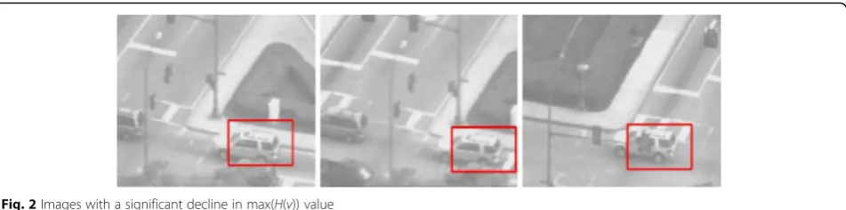
From Fig.1, we can see that max(H(v)) value at 127th frame, 136th frame, and 220th frame has been greatly
re-duced. Figure 2 shows the tracking target at 127th
frame, 136th frame, and 220th frames.
It can be seen from Fig.2 that all of three frames have different degrees of occlusion. When the tracking target is not occluded, max(H(v)) appears a trend of gradual growth and tends to be stable. Therefore, it can be judged by the change of max(H(v)) that the target has
larger deformation or occlusion. LetC(k) be the discrim-ination degree for the occlusion or larger deformation of thekth frame, which can be defined as:
C kð Þ ¼H
k−1−Hk
Hk−1 ð7Þ
where Hk−1 represents the maximum confidence
max(H(v)) at the frame k−1 andHk represents the max-imum confidence max(H(v)) at the framek.
Given a thresholdξ, ifC(k) >ξ, the target is considered as completely occluded or disappeared; ifC(k) <ξ, the target is in the normal tracking state or partial occlusion state.
3.2 Occlusion tracking
In general, occlusion starts from the edge of the target. In the process of the occlusion, the feature of the region that is occluded will be lost, but the feature of the region that is not occluded still maintains the original feature infor-mation. As long as sub-regions without occlusion can be tracked, the target can be accurately located through sub-regions without occlusion. Therefore, a compressive tracking algorithm based on sub-regions is proposed in this paper. The main idea of the algorithm is to divide the target region into several sub-regions, the candidate re-gions of each sub-region are created, the candidate region compression features of each sub-region are extracted, H(v) is calculated by the Bayesian classifier, and the region with the maximum confidence in terms of the compres-sion feature of candidate sub-regions is selected to calcu-late the discrimination degree C(k). IfC(k) <ξ, the target region is located according to position of sub-regions without occlusion. IfC(k) >ξ, the target is completely oc-cluded or disappearing.
The division of sub-regions has a great impact on the tracking effect. Each sub-region may be overlapped or non-overlapping; sub-region size can be fixed or adap-tive. If the sub-region is too large, it will be too sensitive to occlusion, while if the sub-region is too small, it may lose target information and there will be too many sub-regions; thus, the computational cost of the algo-rithm will be very high. In this paper, the target is di-vided into four sub-regions.
As you can see from Fig. 3, if the sub-region 1 is cluded, the upper left corner in the target area is oc-cluded. If the sub-regions 1 and 2 are occluded, the upper half part in the target area is occluded, and so on. We can not only distinguish effectively whether the tar-get is occluded but also determine the location of the target according to the sub-regions that have not been occluded through method for the sub-region.
SupposeDik−1i∈{1, 2, 3, 4} denotes theisub-region in
the frame k−1, the i candidate sub-regions of the
Tið Þ ¼m zjI zð Þ−Dit−1<r
ð8Þ
where γ denotes the neighborhood radius. Supposing
Ti(m) denotes themth candidate region of the sub-region
i, all candidate region compression featuresV(k) are com-puted according to Eq. (3),H(v) is computed according to Eq. (4), and select the candidate region with the maximum confidence to calculate the C(k). If C(k) >ξ, the target is completely blocked or disappearing, and the target is lo-cated according to the feature matching method; other-wise, the target is located according to position of the sub-region with maximumC(k).
After the target is successfully located, the classifier parameters need to be updated according to the CT al-gorithm. In order to reduce the impact by occlusion, only the sub-regions without occlusion update the prob-ability distribution of the features. Therefore, after the target position is determined, the main steps of updating classifier parameter are as follows:
Step 1: Calculating the confidence Hi(v) of all the
sub-regions of target region;
Step 2: Calculating the discrimination degree Ci(k) of
all sub-regions;
Step 3: Judging by the Ci(k) value whether the
sub-region is occluded or not. IfC(k) >ξ, the classifier is
not updated. If not, the classifier will be updated. The updating method is as follows:
1. The positive and negative samples of sub-regions with
Ci(k) <ζare created. The specific method can be de-fined as:
Ti¼fzjkI zð Þ−Ditk<rg
Bi¼fzjα<kI zð ÞDitk<βgγ<α<β ð 9Þ
2. According to the Eq. (3), the featureVican be obtained. The calculation of the parametersu1
i,δ1i,
u0
i, andδ0i is as follows:
u1
i ¼ 1 n
Xn−1
m¼0 Vm
δ1
i ¼
ffiffiffiffiffiffiffiffiffiffiffiffiffiffiffiffiffiffiffiffiffiffiffiffiffiffiffiffiffiffiffiffiffiffiffiffiffiffiffiffiffiffiffiffiffiffi
1 n
Xn−1
m¼0
Við Þ−m u1ið Þm
2
v u u t
u0i ¼ 1 n
Xn−1
m¼0 BVm
δ0
i ¼
ffiffiffiffiffiffiffiffiffiffiffiffiffiffiffiffiffiffiffiffiffiffiffiffiffiffiffiffiffiffiffiffiffiffiffiffiffiffiffiffiffiffiffiffiffiffiffiffi
1 n
Xn−1
m¼0
BVið Þ−m u0ið Þm
2
v u u t
ð10Þ
This algorithm model for sub-regions partition and
classifier updating is shown in Fig. 4. As can be seen
from Fig. 4, this method can not only judge the target
state effectively, but also has good robustness to partial occlusion, local gray change, and deformations.
3.3 Target re-locate
This method in this paper can deal well with the track-ing problem of partial occlusion. But when the target is completely occluded or disappeared, the algorithm can-not track and locate the target accurately. The target de-tection mechanism in the TLD algorithm is introduced Fig. 3The division of sub-regions
in this paper. A method of target re-location based on improved ORB feature matching is proposed. Firstly, fast corner points are gained, and then, false corner points are removed; finally, the BRIEF descriptor is used to de-scribe the corner points.
(a) Fast corner
In [17], in the neighborhood of a pixel, there are many pixels that are larger than or smaller than the gray level of that point; the pixel will be the corner point, which is de-fined as:
N¼ X ∀x∈circleð Þp
I xð Þ−I pð Þ
j j>εd ð11Þ
where I(p) means the gray value of the candidate
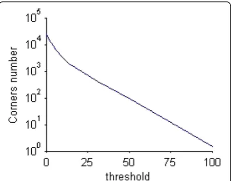
pixel, I(x) represents any pixel of the circular boundary with p as the center, and εd is the threshold. Different
thresholdεdcan be used to control the number of
cor-ner points, and the relationship between the threshold
value and the number of corners is shown in Fig.5. In
order to quickly remove the false corner, εdvalue is 12
in this paper.
(b) Removing edge points
Fast corner points include many edge points and local non-maximum points. The curvature of edge point is larger in the direction perpendicular to the direction of the edge, and smaller along the direction of the edge, while the principal curvatures of the real corner points is larger in any direction [18]. Therefore, the edge points can be removed from fast corner points by principal
curvature. In this paper, the principal curvature is calcu-lated by the 2 × 2 Hessian matrixH, which is defined as:
H xð;yÞ ¼ Dxx Dxy
Dxy Dyy
ð12Þ
The four elements ofHcan be obtained by the adjacent difference. According to the property of Hessian matrix, the principal curvature ofH is proportional to the eigen-value of Hessian matrix. Since the principal curvature of the real corner point is larger in any direction [18], if the difference between the two eigenvalues is larger, it shows that the candidate corner point is on the edge; otherwise, the candidate corner is the real corner point. Here, we do not directly calculate two eigenvalues but calculate the ratio
of two eigenvalues. Let α be the larger eigenvalue of H
matrix,βis its smaller eigenvalue.
Trð Þ ¼H DxxþDyy¼αþβ Detð Þ ¼H DxxDyy−Dxy
2
¼αβ
ratio¼Trð ÞH 2
Detð ÞH ¼
αþβ
ð Þ2
αβ
ð13Þ
In Lowe’s paper [19],α=γβ, ratio = (γ+ 1)2/γ, and (γ= 10). If ratio is less than (10 + 1)2/10, the feature points are preserved, otherwise discarded.
(c) Removing the pseudo corner points
The edge points can be removed via the steps (b). But there are still some local non-maximum points. It can be further judged by calculating the Laplace value of the pixels in the small neighborhood around the candidate corner point; if the candidate corner point is the Laplace extreme point, then the corner point is preserved and vice versa [20]. The calculation of Laplace extremum is as follows:
L xð Þ ¼ X ∀ðp;qÞ
I pð Þ þI qð Þ−I xð Þ
ð Þ ð14Þ
(d) The direction of the fast corner point
Fast corner point does not have direction. In [21], the direction of fast feature points is obtained by gray cen-troid method. The specific methods are as follows:
Firstly, the moment of the neighborhood of the feature point is computed. Thei+jmoment is defined as:
Mij¼
X
x
X
y
xiyjI xð;yÞ ð15Þ
And then the centroid is obtained with these moments.
C¼ Cx;Cy
¼ M10 M00 ;M01 M00
ð16Þ
The orientation of the centroid then simply is
θ¼ arctan Cy
Cx
ð17Þ
whereM00¼X
x X
y
Iðx;yÞ, M10¼X x
X
y
xIðx;yÞ,
andM01¼X
x X
y
yIðx;yÞ.
(e) BRIEF descriptor
The BRIEF descriptor is a bit string description of an image patch from a set of binary intensity tests; a binary testτis defined as
τðp;x;yÞ ¼ 1 if p xð Þ<p yð Þ 0 other
ð18Þ
wherep(⋅)denotes the function of binary comparisons and (x,y) is a sample pair. Each test sample is a ran-domly 5 × 5 window of a 31 × 31 pixel patch. The feature is defined as a vector ofnbinary tests:
fn
dð Þ ¼p
X
1≤i≤n
2i−1τðp;x;yÞ ð19Þ
As a result, the length of descriptor is n. n= 128,
256, 512…, in this paper, n= 256. The function p(x) is computed as a gray values sum in the5 × 5 window
around pixel x. In order to improve the
computa-tional speed, the method of integrating graphs is used to compute the sum of the gray value of the image patch.
The BRIEF descriptor is robust to illumination changes, but it is sensitive to noise and rotation. In order to solve the noise sensitive problem, the image is prepro-cessed by Gauss filter in the ORB algorithm. In order to solve the problem of rotation invariance, for feature set ofn, binary tests at location(x,y)define a 2 ×nmatrix.
S¼ x1……xn
y1……yn
ð20Þ
The rotation matrix Rθis generated using FAST
prin-cipal direction angleθ, which is defined as:
Rθ¼ −cossinθθ consinθθ
ð21Þ
Therefore, feature set with orientation at location (x,y) is defined as:
Sθ ¼RθS ð22Þ
Now, the new feature descriptor becomes:
gnðp;θÞ ¼fn
dð Þ jp ðxi;yiÞ∈Sθ
ð23Þ
The BRIEF with orientation has larger variance and a mean near 0.5, which makes its description performance more irrelevant and distinguishable [22].
In the end, 256 high variance and uncorrelated binary strings are selected as the final ORB descriptors by greedy algorithm, and the specific steps are as follows:
1. The first element in the setT, which is composed of all binary strings, is put into the result setR. 2. The elements in the set T are in turn compared
with the elements in the set R. If the correlation between them is greater than a given threshold value, the binary string is abandoned; otherwise, it will be added to the container R.
3. Repeat step 2 until there are 256 elements in the result set R. If the number of elements in the result set R is less than 256, then the
Fig. 7Tracking algorithm based on ORB feature
correlation threshold is increased and the greedy algorithm is performed again, until there are 256 binary strings in the result set R.
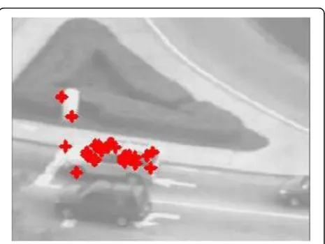
Figure 6 shows the matching results based on ORB
features. As can be seen from Fig. 6, most of the
matching points are focused on the right targets, and only a few of them are wrong.
In order to improve the robustness of the algorithm, the reference point of the target location is decided by
the median values of the matched feature points in the horizontal and vertical, which is defined as:
x0¼midð Þxi
y0¼midð Þyi ð24Þ
where mid(xi)represents the median value of the
hori-zontal coordinates and mid(yi)represents the median
value of the vertical coordinates.
The reference point is selected as the center point of the target tracking, and the coordinates of the upper left corner Fig. 9Template library establishment and update
of the tracking box are calculated according to Eq. (25), so that the position of the tracking target could be determined.
rect:x¼x0−1
2width rect:y¼y0−1
2height
ð25Þ
where rect. x and rect. y, respectively, mean the co-ordinate of upper left corner of tracking box and width and height are the tracking box’s width and height, re-spectively. The target detection based on ORB features is shown in Fig.7:
The partial matching results based on the ORB on car video are shown in Fig.8.
It can be seen from Fig. 8 that the method based on
ORB feature matching can track the target accurately
when there are many matching points. Combined with CT algorithm, the method in this paper can effectively improve the accuracy of tracking.
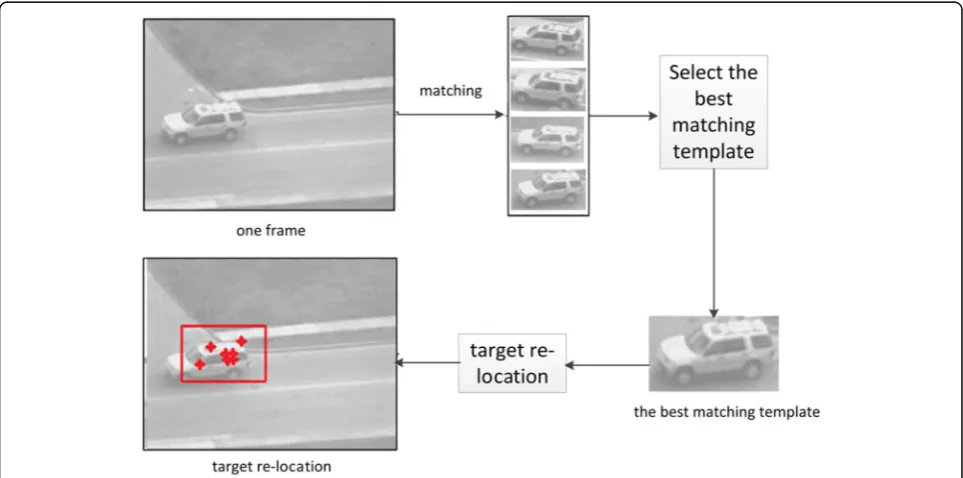
When the target is re-located by ORB feature, the accur-acy of position depends on the number of successful matching feature points. When the target appears again, if there is a huge change in shape, the number of successful matching feature points may be less, which results in the difficulty of accurate positioning. Aiming at this problem, a matching template library is constructed in this paper. After the target is lost, all the templates in the template library are used to search the target. If a template in a template li-brary matches a frame image, the number of matching points is greater than the given threshold value, the tem-plate is considered as the matching temtem-plate. The matching template with the largest number of matching points is
called the best matching template. Then, the location of the target is determined according to the matching points corre-sponding to the best matching template. In order to im-prove the speed of matching, there are not too many templates in the template library; therefore, in this paper, a new method for updating similar templates is proposed. Firstly, the tracking state is determined by tracking module. If the target is in the normal tracking state, the ORB feature of the target area is extracted. Then, the extracted ORB fea-ture is matched with the template in the template library in turn. If the number of matching points is less than the given threshold t, this area is added to the template library, as shown in Fig.9.
By updating the template library, some templates are stored in the template library, which improves the robust-ness of the matching. In order to improve the positioning accuracy, the best template matching strategy is proposed in this paper. The specific process is shown as follows:
1. After the target is lost, all the templates in the template library are used to search the target, respectively. 2. If a template exists in the template library, the
number of matching points with the current image is greater than the given threshold, and then, the template is the matching template;
3. If there may be multiple matching templates, the template with the largest number of matching points is considered as the best matching template; 4. The location of the target is determined according to
the best matching template, and the relocation is completed.
The template matching process is shown in Fig.10:
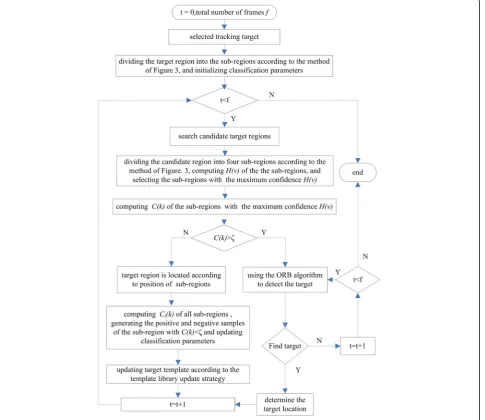
3.4 Algorithm flow
The flow chart of the improved CT algorithm based on tar-get division and feature point matching is shown in Fig.11.
4 Results and discussion
In order to verify the effectiveness of this proposed algo-rithm, the algorithm is implemented by VS2010 +OpenCV2.4 and ran on the computer of Intel Corei7-4510U @2.0GHz processor, and 8GB of RAM, using car video for testing, and compared with the ori-ginal CT algorithm. The testing error in the experiment is given by the below equation:
errorð Þ ¼i
ffiffiffiffiffiffiffiffiffiffiffiffiffiffiffiffiffiffiffiffiffiffiffiffiffiffiffiffiffiffiffiffiffiffiffiffiffiffiffi
xi−xti
ð Þ2þ
yi−yti
ð Þ2
q
ð26Þ
(a)
(b)
(c)
(d)
(e)
(f)
Fig. 12Tracking results of the partial car video.a,b,c,d,eandfrepresent 10th frame, 20th frame, 30th frame, 40th frame, 50th frame and 60th frame, respectively
where (xi,yi) and (xti,yti) represent the central point
coordinates of the predicted target and the real target, respectively.
4.1 Comparison and analysis of partial occlusion
Figure 12 shows the partial tracking results of the two
algorithms in the first 60 frames of the car video. The blue rectangle indicates the tracking result of CT algo-rithm, and the red rectangle is the tracking result of the
improved algorithm. As can be seen from Fig.12, since
the 30th frame, the target is gradually getting away from sight of the camera. The tracking window of the original CT algorithm is constantly shifting to the right, while the target can be more accurately tracked using our im-proved method. Because the imim-proved method is based on sub-regions, relied on the information of the non-obscured sub-regions, the position of the target can be predicted. After the 50th frame, the target is shown wholly in the video; the tracking window of the original CT algorithm is shifting to right for a large number of background information being counted into the update of parameters, while the target can be precisely tracked
again using the improved algorithm. Figure13plots the
tracking error in terms of precisely the first 60 frames. It can be seen from Fig.13that there is no larger occlusion in the first 20 frames of the car video, and the tracking error of the original CT algorithm and the improved al-gorithm in this paper is small. The target is gradually getting out of the camera scene from 30th frames to 40th frames, and the tracking error of the original CT al-gorithm is increasing, but our proposed alal-gorithm can provide constantly good performance, due to the im-proved algorithm can determine the location of the
obscured target more accurately based on the
non-obscured sub-regions of the target. The target grad-ually reappears from 50th frames, and the tracking error of the original CT algorithm is still high; this is because the original CT algorithm has learned a lot of back-ground information, which makes the predicted tracking position deviate from the target region, while the result of our improved algorithm is relatively stable. Therefore, the algorithm in this paper is more accurate and robust when the target is partially occluded.
4.2 Comparison and analysis of complete occlusion
Figure 14 shows the partial tracking results of the two
algorithms in 560–600 frames of the car video. The blue rectangle box represents the tracking result of the CT al-gorithm. The red rectangle box is the tracking result of
(a)
(b)
(c)
(d)
(e)
(f)
Fig. 14 Tracking results of the partial car video.a,b,c,d,eandfrepresent 560th frame, 565th frame, 570th frame, 575th frame, 580th frame and 600th frame, respectively
the improved algorithm. It can be seen from Fig. 14, from the 560th to the 565th frames, that the tracking box of the improved algorithm disappears, and the tracking results of the original CT algorithm shows a large offset. This is because the determination method of target disappearance is introduced in this paper. The original CT algorithm cannot judge the disappearance of the target, so when the target is completely blocked or completely off the scope of the camera, the CT algo-rithm updates a lot of background information; thus, background is wrongly used as a target. At the 570th frame, the tracking box of the proposed algorithm ap-pears again, and the location of the target is quite accur-ately re-located; in contrast, the tracking result of the original CT algorithm deviates completely from the tar-get. The performance advantage of our proposed algo-rithm should thank to the re-location method based on ORB feature matching.
Figure 15 shows the tracking error diagram from
560th frame to 600th frame. As the discriminating mechanism in the target occlusion or disappearance sit-uations introduced in our improved algorithm, the track-ing error from 560th frame to 568th frame cannot be calculated, so it is set to null value. We can tell from Fig.15that the proposed algorithm can relocate the tar-get after the tartar-get is lost and the tracking error can be kept at a relatively stable and low level after the reloca-tion, while in the CT algorithm, because the classifier learns the information of the obstruction, the obstruc-tion might be regarded as the target by mistake, and then, the tracking error becomes larger and larger.
Table1shows the average error of the tracking results of the two algorithms in the car video. As can be seen from the table, this improved algorithm is better than the CT algorithm; the tracking accuracy is higher.
From the above two experiments, it can be seen that the original CT algorithm is potential to update a lot of background information because it does not judge the occlusion when facing the occlusion problem, which makes the background mistakenly considered as the tar-get and makes the error larger; the improved algorithm
can judge the target’s state effectively by dividing
Table 2Processing rate (frames/s)
Algorithm Car
CT algorithm 24
Improved algorithm 18
Fig. 16Comparison results of two algorithms on car video
Table 1Average error
Algorithm Car
CT algorithm 84.428
sub-regions. When the target is in normal tracking and partial occlusion, the target is located accurately using the sub-regions with the highest discriminate degree. The classifier only updates the unblocked sub-region, which avoids updating background information. When the target is completely occluded or lost, the target can be located by the method of the ORB feature matching, which makes up with the deficiency of the original CT algorithm and improves the tracking accuracy.
4.3 Comparison and analysis of time efficiency
Table2lists the calculation speed of the two algorithms.
As can be seen from Table 2, the proposed algorithm
has not doubled the time efficiency compared with the original CT in the case of an increase of four times the number of candidate targets at most. This is because the most time-consuming part of the calculation is the fea-ture extraction; this part of the calculation is done by the integral graph in one time. At the same time, when facing partial occlusion, the classifier is only updated for the unblocked sub-region, which also reduces the pro-cessing time.
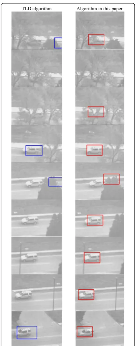
4.4 Comparison between the algorithm in this paper and TLD algorithm
TLD algorithm is the most popular tracking algorithm, which combines tracking algorithm and recognition al-gorithm, and introduces the tracking failure identifica-tion mechanism. Inspired by the design of TLD algorithm, the algorithm in this paper introduces the tar-get detection mechanism on the basis of original CT
al-gorithm. Figure16shows the tracking effect of the TLD
algorithm and the algorithm in this paper on the same frame of the car video.
It can be seen from Fig. 16 that the proposed
algo-rithm has better stability. This is because our algoalgo-rithm of this paper mainly depends on the CT algorithm. The CT algorithm has the advantages of classifier updating and learning, which is more accurate and robust than the L-K optical flow in the TLD algorithm. In the TLD algorithm, if there is difference between the target and template in the TLD template library, it will be difficult for TLD algorithm to detect the target.
Table 3 lists the test results of the two algorithms.
Table 3 indicates that the algorithm proposed in this
paper shows better performance compared to the TLD algorithm, and false rate and missing rate are both lower.
5 Conclusions
Aiming at the problem of poor ability of anti-occlusion in compressive tracking (CT), an improved CT algo-rithm based on target segmentation and feature point matching is proposed. The problem of target tracking in occlusion is solved by target segmentation. The target is captured again by local feature matching after the dis-appearance of the target. The experimental results show that the improved algorithm has strong robustness. However, the method still has some shortcomings. For example, when the target reappears, the scale of the target may change and the scale of the target tracking box needs to be solved after relocation.
Abbreviations
CRF:Corner response function; CT: Compressed tracking; ORB: ORiented Brief; TLD: Tracking learning detection
Acknowledgements
The authors thank the editor and anonymous reviewers for their helpful comments and valuable suggestions.
Funding
This work was supported in part by a grant from the National Natural Science Foundation of China (No. 61403060, 61603146), a grant from Six-talent peaks project in Jiangsu Province, China (No. XYDXXJS-012), Research on Natural Science of Colleges and Universities in Jiangsu(No.15KJA460003), Modern Educational Technology of Jiangsu (No.2016-R-49007), Top-notch Academic Programs Project of Jiangsu Higher Education Institutions,Science and Technology Project in Huai'an City(No.HAG201602), and the Key Labora-tory of Intelligent City and Virtual Reality in Huai'an City(No.HAP201605).
Availability of data and materials We can provide the data.
Authors’contributions
All authors take part in the discussion of the work described in this paper. The author WW wrote the first version of the paper, the author WZ did part experiments of the paper, and MJ, YY, and XC revised the paper in different version of the paper, respectively. All authors read and approved the final manuscript.
Authors’information
Wenhao Wang received his B.S. degree in Mechatronics from Nanjing University of Science and Technology, Nanjing, China, in 2000, and the M.S. degree in software engineering from Nanjing University of Science and Technology, Nanjing, China, in 2004. He is currently an associate professor in the Faculty of Computer & software Engineering at Huaiyin Institute of Technology. His research interests include digital image processing, pattern recognition, and algorithm optimization. Contact: [email protected] Mingxin Jiang received her B.S. degree in Measurement & Control Technology and Instrument and the M.S. degree in Communications and Information System from Jilin University, Changchun, China, in 2002 and 2005. She received a Ph.D. degree in Signal and information processing, Dalian University of Technology, China, in 2013. She was a post-doctoral re-searcher with the Department of Electrical Engineering in Dalian University of Technology from 2013 to 2015. She is currently an associate professor in Faculty of Electronic information Engineering at Huaiyin Institute of
Table 3The comparison of false rate and missing rate on the car video
Algorithm Frames False detection number Missing rate (%) Missed rate (%)
TLD 810 25 16.93 2.64
Technology. Her research interests include multi-object tracking, video con-tent analysis, and vision sensors for robotics. Contact: [email protected] Yunyang Yan received his B.S. degree in Computer Science and Technology from Nanjing Institute of Aeronautics, Nanjing, China, in 1988, the M.S. degree in Computer Science and Technology from Southeast University, Nanjing, China, in 2002, and the Ph.D. degree in Pattern Recognition and Intelligent System from Nanjing University of Science and Technology, Nanjing, China, in 2008. He is currently a professor in Faculty of Computer & Software Engineering at Huaiyin Institute of Technology. His research interests include digital image processing, pattern recognition, and management information system. Contact: [email protected] Xiaobing Chen received his B.S. degree in Mechanical Manufacture & Automation, the M.S. degree in Computer Graphics, and the Ph.D. degree in Aeronautical & Astronautic Manufacturing, from Nanjing University of Aeronautics & Astronautics, China, in 1992, 2003, and 2012, respectively. He is currently a professor in Faculty of Computer and Software Engineering at Huaiyin Institute of Technology. His research interests include computer graphics, 3D modeling, and 3D printing. Contact: [email protected] Wendong Zhao received his B.S. degree in Electronic Engineering and the M.S. degree in Computer Technology from Jiansu University, Zhenjian, China, in 1996 and 2007, respectively. He is currently an associate professor in Faculty of Computer and Software Engineering at Huaiyin Institute of Technology. His research interests include graphics and image processing, video content analysis, and Internet of Things engineering. Contact: [email protected]
Ethics approval and consent to participate Approved.
Consent for publication Approved.
Competing interests
The authors declare that they have no competing interests, and all authors have seen the manuscript and approved to submit to your journal. We confirm that the content of the manuscript has not been published or submitted for publication elsewhere.
Publisher’s Note
Springer Nature remains neutral with regard to jurisdictional claims in published maps and institutional affiliations.
Received: 19 April 2018 Accepted: 3 July 2018
References
1. S Wang, H Lu, F Yang, et al., inProceedings of the IEEE Conference on Computer Vision: November 6–13, 2011. Superpixel tracking (IEEE, Barcelona, 2014), pp. 1323–1330
2. A Bugeau, P Perez, Track and cut: simultaneous tracking and segmentation of multiple objects with graph cuts. EURASIP Journal on Image and Video Processing.2, 447–454 (2008)
3. S Oron, A Bar-Hillel, D Levi, S Avidan, Locally orderless tracking. Int. J. Comput. Vis.111, 213–228 (2015)
4. J Kwon, KM Lee, inProceedings of the IEEE Conference on Computer Vision and Pattern Recognition: June 20–25, 2009. Tracking of a non-rigid object via patch-based dynamic appearance modeling and adaptive Basin Hopping Monte Carlo sampling (IEEE, Miami, FL, 2009), pp. 1208–1215
5. Z Kalal, J Matas, K Mikolajczyk, inProceedings of the IEEE Conference on Computer Vision Workshops: Sept. 27 2009–Oct. 4 2009. On-line learning of robust object detectors during unstable tracking (IEEE, Kyoto, 2009), pp. 1417–1424
6. G Helmut, inProceedings of the British Machine Vision Conference: September 4-7, 2006. Real-time tracking via on-line boosting (IEEE, Edinburgh, 2006), pp. 47–56
7. A Adam, E Rivlin, I Shimshoni, inProceedings of the IEEE Conference on Computer Vision and Pattern Recognition: June 17–22, 2006. Robust Fragments-based Tracking using the Integral Histogram (IEEE, New York, 2006), pp. 798–805
8. SMS Nejhum, J Ho, MH Yang, Visual tracking with histograms and articulating blocks. Computer Vision & Image Understanding114, 901–914 (2008)
9. HX Li, CH Shen, QF Shi, inProceedings of the IEEE Conference on Computer Vision and Pattern Recognition: June 20–25,2011. Real-time visual tracking using compressive sensing (IEEE, Colorado Springs, 2011), pp. 1305–1312 10. K Zhang, L Zhang, MH Yang, inProceedings of the European Conference on
Computer Vision: October 7–13, 2012. Real-time compressive tracking (Springer, Florence, 2012), pp. 866–879
11. PM Fonseca, J Nesvadba, Face tracking in the compressed domain. EURASIP Journal on Advances in Signal Processing.1, 1–11 (2006)
12. K Zhang, L Zhang, MH Yang, Fast compressive tracking. IEEE Trans. Pattern Anal. Mach. Intell.36(10), 2002–2015 (2014)
13. QP Zhu, J Yan, DX Deng, Compressive tracking via oversaturated sub-region classifiers. IET Comput. Vis.17(6), 448–455 (2013)
14. L ZHANG, J HAN, B LI, et al., The scale adaptive feature compressed tracking. J Natl Univ Defense Technol35, 146–151 (2013) 15. PA Deotale, VJ Preetida, Object detection and localization using
compressed sensing. Advances in Signal Processing and Intelligent Recognition Systems678, 127–141 (2018)
16. DL Donoho, Compressed sensing. IEEE Trans. Inf. Theory52, 1289–1306 (2006)
17. E Rosten, T Drummond, inProceedings of the European Conference on Computer Vision: May 7–13, 2006. Machine learning for high-speed corner detection (Springer, Graz, 2006), pp. 430–443
18. MS Verkeenko, Development of an algorithm for fast corner points detection. Journal of Computer and Systems Sciences International53(3), 392–401 (2014)
19. DG Lowe, Distinctive image features from scale-invariant keypoints. Int. J. Comput. Vis.60, 91–110 (2004)
20. TTH Tran, E Marchand, inProceedings of the IEEE Conference on Robotics and Automation: April 10–14, 2007. Real-time keypoints matching: application to visual servoing (IEEE, Roma, 2007), pp. 3787–3792
21. E Rublee, V Rabaud, K Konolige, et al., inProceedings of the IEEE Conference on Computer Vision: Nov 6–13, 2011. ORB: an efficient alternative to SIFT or SURF (IEEE, Barcelona, 2012), pp. 2564–2571