R E S E A R C H
Open Access
Robust semi-automatic 2D-to-3D image
conversion via residual-driven optimization
Hongxing Yuan
Abstract
Semi-automatic 2D-to-3D conversion provides a cost-effective solution to the problem of 3D content shortage. The performance of most methods degrades significantly when cross-boundary scribbles are present due to their inability to remove unwanted input. To address this problem, a residual-driven energy function is proposed to remove unwanted input introduced by cross-boundary scribbles while preserving expected user input. Firstly, confidence of user input is computed from residuals between the estimation and user-specified depth values, and it is applied to the data fidelity term. Secondly, the residual-driven optimization is performed to estimate dense depth from user scribbles. The procedure is repeated until a maximum number of iterations is exceeded. Input confidence based on residuals avoids the propagation of unwanted scribbles and thus enables to generate high-quality depth even with cross-boundary input. Experimental results demonstrate that the proposed method removes unwanted scribbles successfully while preserving expected input, and it outperforms the state-of-the-art when presented with cross-boundary scribbles.
Keywords: 3D video, 2D-to-3D conversion, Depth, Cross-boundary scribbles, Optimization
1 Introduction
2D-to-3D conversion aims to estimate depth from 2D images and generates stereoscopic views from the depth, which is a key technology to produce 3D content [1]. Existing approaches are mainly categorized into two groups: automatic and semi-automatic methods.
Automatic methods try to create depth from 2D images using various depth cues, such as dark channel [2], motion [3], lighting bias [4], defocus [5], geometry [6], boundary [7], etc. Each cue is only applicable to certain scenes [8], and thus, these methods are hard to provide acceptable results in any general content. Recently, neural networks have been employed to learn the implicit relation between depth and color values [9–12]. However, these learning-based methods are limited to the trained image types [13]. Semi-automatic methods address these issues by intro-ducing human interactions. The objective of these approaches is to produce a dense depth-map from user scribbles which indicate the labeled pixels are farther or closer from the camera [14]. In order to solve the problem
pri-Yuan et al. [22] incorporated non-local neighbors into the RW algorithm to improve depth quality. Liang et al. [23] extended this scheme to support video conversion using spatial-temporal information. Wang et al. [24] prop-agated user-specified sparse depth into dense depth using an optimization method originally used for colorization [25]. Wu et al. [26] improved this method with depth consistency between superpixels. Liao et al. [27] used a diffusion process to generate a depth map from user coarse annotations.
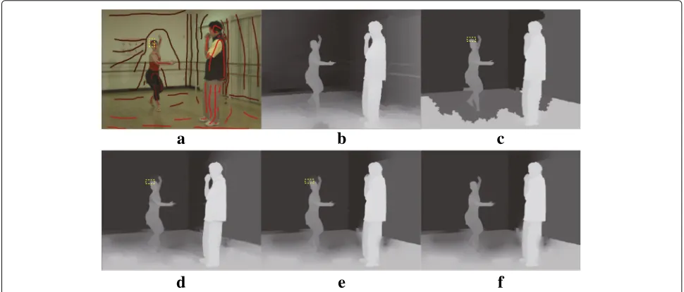
Depth-map is typically made of smooth regions sepa-rated by sharp transitions along the boundaries between different objects [28]. Therefore, existing semi-automatic methods require that user scribbles do not cross object boundaries; otherwise, the quality of produced depth degrades significantly. As shown in Fig.1, when user scrib-bles cross object boundaries, the state-of-the-art methods [18, 22, 24] will produce depth artifacts. In 2D-to-3D conversion, the cross-boundary scribbles are introduced by users carelessly. As for a cross-boundary scribble, its longer part is usually user expected input and shorter part is unwanted input. It can be seen from Fig. 1f that the proposed method can remove depth artifacts caused by unwanted user input from cross-boundary scribbles.
Semi-automatic image segmentation methods have addressed the problem of cross-boundary scribbles [29–31]. Although Subr et al. [29] and Bai et al. [30] can reduce artifacts caused by cross-boundary scribbles, they focus on the foreground object segmentation and are hard to apply in 2D-to-3D conversion. Oh et al. [31] used occur-rence and co-occuroccur-rence probability (OCP) of color values
at labeled pixels to estimate the confidence of user input. This method can be used for 2D-to-3D conversion, but it may mistake expected scribbles for unwanted ones.
Surprisingly, there are few methods to consider the impact of cross-boundary scribbles on 2D-to-3D con-version. To address this problem, we propose a robust method based on residuals between the user-specified and estimated depth values during the iteratively solving process. Thanks to the confidence of user scribbles mea-sured by the residuals, experimental results show that the proposed method can remove depth artifacts caused by cross-boundary scribbles. The two most relevant to this work are Wang et al. [24] and Hong et al. [32]. Unlike the optimization model in Wang et al. [24], the proposed method utilizes residuals to eliminate the depth artifacts caused by cross-boundary scribbles. The main difference to Hong et al. [32] is that they use residuals to determine the relative weight between data fidelity and regulariza-tion, whereas this paper leverages residuals to compute the confidence of user scribbles.
Recently, Ham et al. [33] proposed a static dynamic filter (SDF) to reduce artifacts caused by structural differences between guidance and input signals. Although SDF [33] can handle differences in structure, it is not robust to out-liers introduced by cross-boundary scribbles. Yuan et al. [34] proposed an1optimization method to remove user erroneous scribbles. However,1norm assumes that input image can be approximated by the sum of a piecewise-constant function and a smooth function [35]. Depth artifacts will be introduced when the assumption does not hold.
a
b
c
d
e
f
Fig. 1Depth estimation with cross-boundary user input (depth artifacts caused by cross-boundary scribbles are marked by yellow rectangles).
aInput image with user scribbles (the cross-boundary scribble is marked by the yellow rectangle).bGroundtruth.cHybrid GC and RW [18].
User Labeling Sparse Depth Extraction
Input 2D image
Confidence Computation
for User Scribbles Based on Residuals Confident Data
Fidelity Term
Regularization Term Energy
Solving DIBR
Energy Function
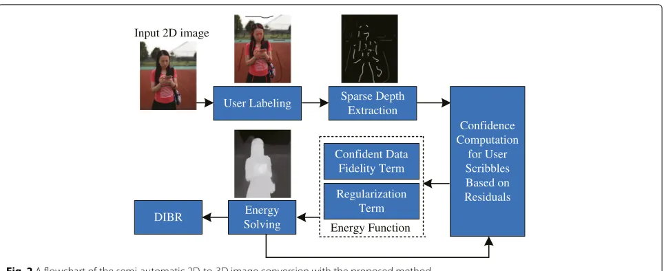
Fig. 2A flowchart of the semi-automatic 2D-to-3D image conversion with the proposed method
The remainder of this paper is organized as follows. In Section2, the proposed method is described. The experi-mental results are given in Section3. Finally, conclusion is given in Section4.
2 Method
The workflow of 2D-to-3D image conversion based on the proposed method is shown in Fig.2. Firstly, the user specifies sparse depth on an input image, where scrib-bles indicate the labeled pixels are closer or farther from the camera. Secondly, a sparse depth-map is extracted according to the intensities of user scribbles. Thirdly, the
confidence of user scribbles is calculated based on the residuals between the estimated and user-specified depth values. Then, an energy function constraint by the confi-dence is designed and minimized to obtain the estimated dense depth-map. The procedure is repeated from the confidence computation step, until a maximum number of iterations is exceeded. Finally, the stereoscopic 3D image is generated by depth image-based rendering (DIBR).
2.1 Model
LetObe the set consisting of pixels with user-specified depth values. The objective of this paper is to estimate
0.4 0.6 0.8 1
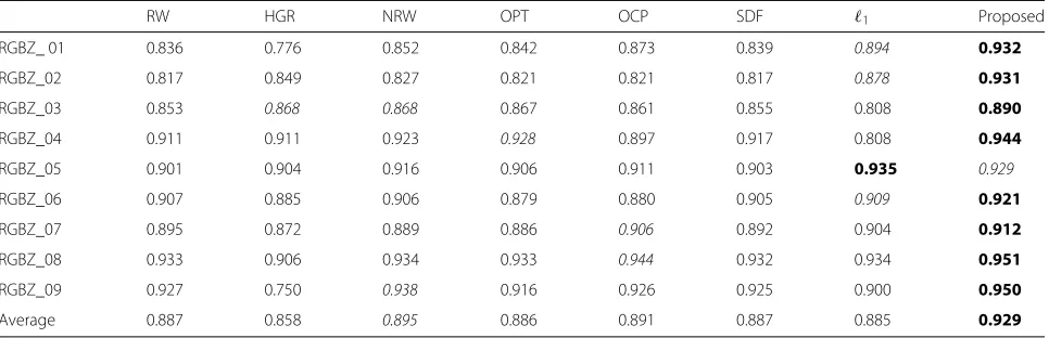
Table 1SSIM of estimated depth on RGBZ datasets when cross-boundary scribbles are present
RW HGR NRW OPT OCP SDF 1 Proposed
RGBZ_ 01 0.836 0.776 0.852 0.842 0.873 0.839 0.894 0.932
RGBZ_02 0.817 0.849 0.827 0.821 0.821 0.817 0.878 0.931
RGBZ_03 0.853 0.868 0.868 0.867 0.861 0.855 0.808 0.890
RGBZ_04 0.911 0.911 0.923 0.928 0.897 0.917 0.808 0.944
RGBZ_05 0.901 0.904 0.916 0.906 0.911 0.903 0.935 0.929
RGBZ_06 0.907 0.885 0.906 0.879 0.880 0.905 0.909 0.921
RGBZ_07 0.895 0.872 0.889 0.886 0.906 0.892 0.904 0.912
RGBZ_08 0.933 0.906 0.934 0.933 0.944 0.932 0.934 0.951
RGBZ_09 0.927 0.750 0.938 0.916 0.926 0.925 0.900 0.950
Average 0.887 0.858 0.895 0.886 0.891 0.887 0.885 0.929
The first and second best SSIM at each row are shown in bold and italics, respectively
an accurate dense depth-mapdfrom the user input and the given image I even when cross-boundary scribbles are present. It can be expressed as solving the energy minimization problem:
d=arg min d∈Rn
i∈O
ri(di−ui)2
data fidelity
+
n
i=1
j∈Ni
wij(di−dj)2
regularization
, (1)
wheredi andui denote the estimated and user-specified depth values at pixel i, respectively. nis the size of the input imageI.Nirepresents the set of 8-connected neigh-bors for pixeli.wij is a weighting function to make pix-els with similar colors have similar depth values and is defined as
wij=
exp−β Ii−Ij 2
ifj∈Ni,
0 otherwise, (2)
whereIiandIjare the color values of imageIat pixeliand
j, respectively.βin Formula (2) is a parameter controlling the strength of the weightwij.
ri in Formula (1) is a confidence measure of the user-specified depth value at pixeliand is defined asz
ri=
exp−η(di−ui)2
ifi∈O,
0 otherwise. (3)
Here, ηis a constant that controls how dissimilar two depth values are. In Formula (1), the data fidelity term enforces the estimated depth values of labeled regions to approximate the user-specified ones. Unlike Wang et al. [24], the proposed method maintains this consistency only when user inputs are confident. The confidenceriis low when the residual(di−ui)2is high. The regularization term is used to penalize the difference of the estimated depth values between each pixel and its neighbors.
2.2 Solver
Formula (1) is nonlinear todand thus is an unconstrained, non-linear optimization. A fixed point iteration strategy is adopted to solve Formula (1). Letdk =
dk i
n×1andu denote vectors representing the estimated depth image in iteration kand user-specified depth values, respectively. The i-th element ofuis user-specified depth valueui if
i ∈Oand 0 otherwise. Then, in iterationk, the objective function to be minimized is expressed as
E
dk
=dk−u T
Rk−1
dk−u
+λdk,TLdk, (4)
whereRk−1is an×ndiagonal matrix and itsi-th diagonal
element isrik−1. Here,rki−1=exp
−ηdki−1−ui
2 ifi∈
Oand 0 otherwise.Lis then×nsparse Laplacian matrix. Its element Lij = −wij (i = j) andLii = j∈Niwij. To
Table 2SSIM of estimated depth on Middlebury datasets when cross-boundary scribbles are present
RW HGR NRW OPT OCP SDF 1 Proposed
Tsukuba 0.724 0.716 0.723 0.727 0.708 0.724 0.722 0.731
Venus 0.969 0.961 0.968 0.970 0.966 0.969 0.971 0.974
Teddy 0.861 0.846 0.865 0.862 0.860 0.861 0.868 0.865
Cones 0.900 0.871 0.900 0.902 0.850 0.897 0.885 0.903
Average 0.864 0.848 0.864 0.865 0.846 0.863 0.862 0.868
a
b
e
f
i
g
h
c
d
j
k
l
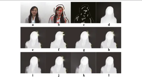
Fig. 4Results of RGBZ_01 with cross-boundary input.aInput image.bUser-labeled image.cSparse depth.dGroundtruth depth.eDepth of RW.
fDepth of HGR.gDepth of NRW.hDepth of OPT.iDepth of OCP.jDepth of SDF.kDepth of1.lDepth of the proposed method. Please zoom in to see details
a
b
c
d
a
b
e
f
i
c
d
g
h
j
k
l
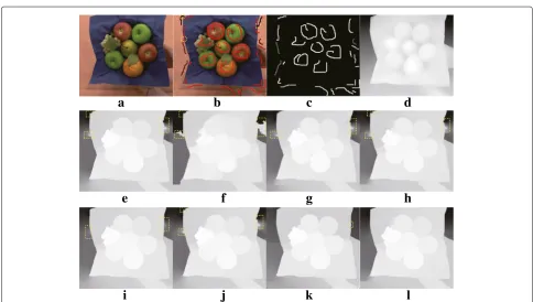
Fig. 6Results of RGBZ_03 with cross-boundary input.aInput image.bUser-labeled image.cSparse depth.dGroundtruth depth.eDepth of RW.
fDepth of HGR.gDepth of NRW.hDepth of OPT.iDepth of OCP.jDepth of SDF.kDepth of1.lDepth of the proposed method. Please zoom in to see details
c
a
e
f
i
j
d
b
g
h
k
l
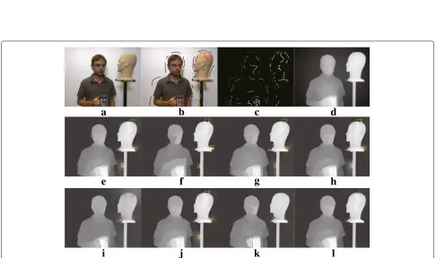
Fig. 7Results of RGBZ_04 with cross-boundary input.aInput image.bUser-labeled image.cSparse depth.dGroundtruth depth.eDepth of RW.
a
b
e
f
i
j
c
d
g
h
k
l
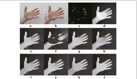
Fig. 8Results of RGBZ_05 with cross-boundary input.aInput image.bUser-labeled image.cSparse depth.dGroundtruth depth.eDepth of RW.
fDepth of HGR.gDepth of NRW.hDepth of OPT.iDepth of OCP.jDepth of SDF.kDepth of1.lDepth of the proposed method. Please zoom in to see details
a
b
e
f
c
d
a
b
e
f
i
j
c
d
g
h
k
l
Fig. 10Results of RGBZ_07 with cross-boundary input.aInput image.bUser-labeled image.cSparse depth.dGroundtruth depth.eDepth of RW.
fDepth of HGR.gDepth of NRW.hDepth of OPT.iDepth of OCP.jDepth of SDF.kDepth of1.lDepth of the proposed method. Please zoom in to see details
a
b
e
f
i
j
c
d
g
h
k
l
Fig. 11Results of RGBZ_08 with cross-boundary input.aInput image.bUser-labeled image.cSparse depth.dGroundtruth depth.eDepth of RW.
minimize the energy function in Formula (4), taking its derivatives ondk, Formula (5) can be obtained.
∂Edk ∂dk =2R
k−1dk−u+2λLdk. (5)
The energy function in Formula (4) can be minimized by
setting ∂E
dk
∂dk in Formula (5) equal to zero, and Formula (6) is obtained.
Rk−1+λL
dk =Rk−1u. (6)
The linear system in Formula (6) is sparse, and thus, it can be solved using standard methods such as pre-conditioned conjugate gradient.
2.3 Analysis
It can be seen from Formula (4) that in each iteration, user-specified depth values can only be preserved if the residuals between estimated and user-specified depth val-ues are small.
Specifically, the unwanted user input introduced by cross-boundary scribbles will make the depth values of labeled pixels differ from their neighbors. Meanwhile, the
regularization term will enforce the estimation to be con-sistent with their neighbors, and thus make the estimated depth to deviate from the user input. As a result, the resid-ual between the estimated and user-specified depth values of the unwantedly labeled pixel will be increased, and the confidence computed from the residual in Formula (3) will be decreased to zero during the iterative solu-tion process. Therefore, the proposed method can remove unwanted user input introduced by cross-boundary scribbles.
As for user-expected input, the specified values of labeled pixels are consistent with their neighbors; thus, the estimation mainly depends on the data fidelity term which enforces the estimated depth to approximate the user input. Therefore, the residuals of expectedly labeled pixels are almost 0, and their confidence will be remained at 1 with the proper setting ofηin Formula (3). For this reason, the proposed method can preserve the expected user input.
Figure 3 shows the change curve of confidence from user scribbles in an input image. It can be seen that confidence of the unwanted input rapidly drops to 0 while confidence of the expected input remains at 1.
a
b
e
f
c
d
3 Experimental results and discussion 3.1 Experimental details
RGBZ (red, green, blue plusz-axis depth) datasets [36] are used for comparison which include objects, human figures, and multiple human interaction. Performance are also evaluated on four Middlebury stereo datasets, Tsukuba, Venus, Teddy, and Cones [37]. The source code and more experimental results can be downloaded from https://github.com/tcyhx/rdopt.
In the proposed method, the bandwidth parameters,η, are empirically set to 9000. A maximum number of five iterations is used to solve Formula (1).β is set to 100 for RGBZ datasets and 50 for Middlebury datasets. Results of the proposed method are compared to the
state-of-the-art: RW [17], hybrid GC and RW (HGR) [18], nonlocal RW (NRW) [22], optimization (OPT) [24], OCP [31], SDF [33], and1[34]. Note that OCP originally aims for inter-active segmentation, and this paper applies it to 2D-to-3D conversion by replacing the confidence in Formula (3) with the aggregation of the OCPs in a local neighbor-hood. Structural similarity (SSIM) [38] is used for perfor-mance evaluation since it can predict human perception of image quality. The standard deviation of SSIM in the experiments is set to 4 so as to evaluate the similarity of semi-global structure [39].
In the experiments, a trained user is asked to draw scrib-bles with a standard brush by referring to the groundtruth depth values, where higher intensities indicate the labeled
i
j
k
l
e
f
g
h
a
b
o
t
c
d
p
n
m
s
q
r
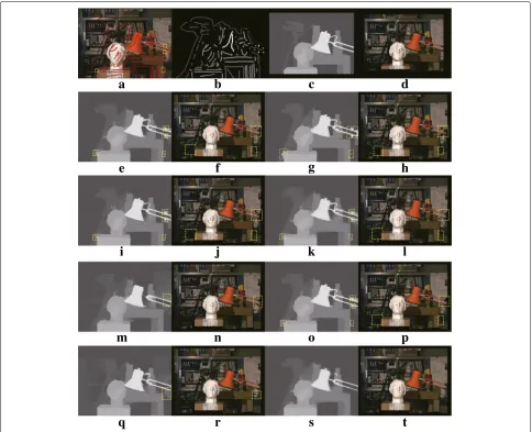
Fig. 13Results of Tsukuba with cross-boundary input.aUser-labeled image.bSparse depth.cGroundtruth depth.dSynthesized view using c.
eDepth of RW.fSynthesized view usinge.gDepth of HGR.hSynthesized view usingg.iDepth of NRW.jSynthesized view usingi.kDepth of OPT.
pixels are closer to the camera. Since depth propagation from user scribbles relies on color or intensity similarity between neighboring pixels, more scribbles are drawn in high textured areas. To make the comparison as fair as possible, a sparse depth-map is extracted from user scrib-bles, and each algorithm estimates a dense depth-map from the sparse depth-map.
3.2 Experiments with cross-boundary user scribbles In this section, a user is asked to assign the initial depth values manually by drawing some scribbles across
object boundaries. Tables 1 and 2 show the SSIM val-ues of the proposed algorithm in comparison with other methods on the RGBZ and Middlebury datasets, respec-tively. As shown in Tables1and2, the proposed method achieves the highest average SSIM among all of the peting methods for both datasets. Except for the com-parison with1in RGBZ_05 and Teddy, the SSIM values of the proposed method are higher than those of the other methods.
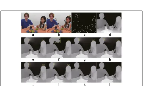
For RGBZ datasets, qualitative comparisons are shown in Figs. 4, 5, 6, 7, 8, 9, 10, 11 and 12. Qualitative
i
j
k
l
e
f
g
h
a
b
o
c
d
p
n
comparisons on Middlebury datasets are given in Figs. 13, 14, 15, and 16. The rendered images based on depth are only shown for Middlebury datasets in order to avoid making the lengthy paper. In each figure, the yellow rectangles on depth-maps or synthe-sized views represent artifacts caused by cross-boundary scribbles while the purple ones denote artifacts caused by other issues. The cross-boundary scribbles of user-labeled images are marked by the yellow rectangles (Figs.4,5,6,7,8,9,10,11,12b,13,14,15, and16a).
RW [17] assumes that user scribbles should not cross object boundaries and thus generates depth
artifacts around cross-boundary labeled regions (see Figs.4,5,6,7,8,9,10,11,12,13,14,15, and16e). These artifacts cause distortions when a new view is synthe-sized from the depth as shown in Figs.13,14,15, and16f. HGR [18] relies on GC to preserve depth boundaries. However, GC is sensitive to the outliers. The quality of depth-maps produced from HGR thus degrades signifi-cantly when user scribbles cross object boundaries (see Figs. 4, 5, 6, 7, 8, 9, 10, 11, 12f, 13, 14, 15, and 16g), which leads to significant degradation of quality in syn-thesized views (see Figs.13, 14,15, and 16h). Although introducing non-local constraints, NRW [22] is difficult
i
j
k
l
e
f
g
h
a
b
o
t
c
d
p
n
m
s
q
r
Fig. 15Results of Teddy with cross-boundary input.aUser labeled image.bSparse depth.cGroundtruth depth.dsynthesized view usingc.
eDepth of RW.fSynthesized view using e.gDepth of HGR.hSynthesized view usingg.iDepth of NRW.jSynthesized view usingi.kDepth of OPT.
i
j
k
l
e
f
g
h
a
b
o
t
c
d
p
n
m
s
q
r
Fig. 16Results of Cones with cross-boundary input.aUser-labeled image.bSparse depth.cGroundtruth depth.dsynthesized view usingc.
eDepth of RW.fSynthesized view usinge.gDepth of HGR.hSynthesized view usingg.iDepth of NRW.jSynthesized view usingi.kDepth of OPT.
lSynthesized view usingk.mDepth of OCP.nSynthesized view usingm.oDepth of SDF.pSynthesized view usingo.qDepth of1.rSynthesized view usingq.sDepth of the proposed method.tSynthesized view usings. Please zoom in to see details
Table 3SSIM of estimated depth on RGBZ datasets when cross-boundary scribbles are absent
RW HGR NRW OPT OCP SDF 1 Proposed
RGBZ_01 0.925 0.913 0.936 0.932 0.924 0.933 0.863 0.934
RGBZ_02 0.932 0.917 0.934 0.928 0.919 0.880 0.920 0.928
RGBZ_03 0.876 0.892 0.890 0.888 0.872 0.881 0.817 0.890
RGBZ_04 0.928 0.936 0.938 0.944 0.907 0.934 0.821 0.945
RGBZ_05 0.925 0.919 0.930 0.928 0.911 0.927 0.934 0.932
RGBZ_06 0.923 0.895 0.921 0.908 0.890 0.908 0.913 0.921
RGBZ_07 0.910 0.892 0.905 0.910 0.910 0.907 0.904 0.915
RGBZ_08 0.949 0.920 0.951 0.949 0.950 0.948 0.939 0.951
RGBZ_09 0.946 0.877 0.953 0.943 0.938 0.918 0.902 0.951
Average 0.924 0.907 0.929 0.926 0.914 0.915 0.890 0.930
The first and second best SSIM at each row are shown in bold and italics, respectively
handle artifacts introduced by the cross-boundary scrib-bles (see Figs. 4, 5, 6, 7, 8, 9, 10, 11, 12j, 13, 14, 15, and16o), which leads to distortions in synthesized views as shown in Figs. 13, 14, 15, and 16p. 1 [34] tends to produce a nearly piecewise constant depth-map with sparse structures. Therefore, it generates artifacts when depth discontinuities do not coincide with object bound-aries (see purple rectangles of Figs.4,5, 6,7, 8,9k,14q, and16q), which causes distortions in synthesized views (see purple rectangles of Figs. 14r and 16r). The pro-posed method alleviates the influence of cross-boundary user scribbles successfully and produces high-quality depth-maps (see Figs. 4, 5, 6, 7, 8, 9, 10, 11, and 12l, and13,14,15and16s). Therefore, the proposed method can reduce distortions in synthesized views caused by cross-boundary input as shown in Figs. 13, 14, 15 and16t.
3.3 Experiments without cross-boundary user scribbles In this section, the user carefully draws on an input image, ensuring that scribbles do not cross object boundaries. In this case, unwanted scribbles are usually inside objects when depth discontinuity occurs. Tables 3 and 4 show the SSIM obtained from different methods on RGBZ and
Middlebury datasets, respectively. It can be seen from Table3that the proposed method gives the highest aver-age SSIM on RGBZ datasets. As shown in Table4, both the proposed method and OPT [24] obtain the high-est average SSIM on Middlebury datasets. Therefore, the proposed method has comparable performance to the state-of-the-art methods when user scribbles do not cross object boundaries.
4 Conclusion
To remove unwanted input from cross-boundary scrib-bles in semi-automatic 2D-to-3D conversion, this paper proposes a residual-driven energy function for depth estimation from user input. The residual between the estimation and user-specified depth value will be large at the unwantedly labeled pixel due to inconsistency with its neighbors and be small at expectedly labeled pixel due to consistency with the neighbors. Therefore, the residual can differentiate unwanted scribbles from the user input. The experimental results demonstrate that the proposed method eliminates the depth artifacts caused by cross-boundary scribbles effectively and out-performs existing methods when cross-boundary input is present.
Table 4SSIM of estimated depth on Middlebury datasets when cross-boundary scribbles are absent
RW HGR NRW OPT OCP SDF 1 Proposed
Tsukuba 0.731 0.725 0.729 0.733 0.711 0.733 0.726 0.731
Venus 0.975 0.970 0.972 0.974 0.966 0.972 0.972 0.975
Teddy 0.865 0.860 0.867 0.866 0.860 0.862 0.869 0.865
Cones 0.904 0.888 0.902 0.905 0.858 0.902 0.892 0.905
Average 0.869 0.861 0.868 0.870 0.849 0.868 0.865 0.870
Abbreviations
RGBZ: Red, green, blue plusz-axis depth; SVM: Support vector machines; RW: Random-walks; GC: Graph-cuts; OCP: Co-occurrence probability; DIBR: Depth image-based rendering; HGR: Hybrid GC and RW; NRW: Nonlocal RW; OPT: Optimization; SSIM: Structural similarity
Acknowledgements
The author would like to thank the editors and anonymous reviewers for their valuable comments.
Funding
This research was supported by Zhejiang Provincial Natural Science Foundation of China under Grant No. LY16F010014, and Ningbo Natural Science Foundation under Grant No. 2017A610109.
Availability of data and materials
The author can provide the data and source code.
Authors’ contributions
HY designed the research, analyzed the data, then wrote and edited the manuscript. The author read and approved the final manuscript.
Authors’ information
Hongxing Yuan is currently an Associate Professor at the School of Electronics and Information Engineering, Ningbo University of Technology, China. He received doctor’s degree from University of Science and Technology of China, in 2010. His current research interests include computer vision, 3D video processing, and 2D-to-3D conversion.
Competing interests
The author declares that he has no competing interests.
Publisher’s Note
Springer Nature remains neutral with regard to jurisdictional claims in published maps and institutional affiliations.
Received: 31 January 2018 Accepted: 17 July 2018
References
1. W Huang, X Cao, K Lu, Q Dai, AC Bovik, Toward naturalistic 2D-to-3D conversion. IEEE Trans. Image Process.24(2), 724–733 (2015) 2. T-Y Kuo, Y-C Lo, C-C Lin, inProceedings of the IEEE Intl. Conf. on Acoustics,
Speech and Signal Process. 2D-to-3D conversion for single-view image based on camera projection model and dark channel model (IEEE, Piscataway, 2012), pp. 1433–1436
3. Y-K Lai, Y-F Lai, Y-C Chen, An effective hybrid depth-generation algorithm for 2D-to-3D conversion in 3D displays. J. Disp. Technol.9(3), 154–161 (2013)
4. H Han, G Lee, J Lee, J Kim, S Lee, A new method to create depth information based on lighting analysis for 2D/3D conversion. J. Cent. South Univ.20(10), 2715–2719 (2013)
5. J Lin, X Ji, W Xu, Q Dai, Absolute depth estimation from a single defocused image. IEEE Trans. Image Process.22(11), 4545–4550 (2013) 6. C-C Han, H-F Hsiao, Depth estimation and video synthesis for 2D to 3D
video conversion. J. Sign. Process. Syst.76(1), 33–46 (2014) 7. T-T Tsai, T-W Huang, R-Z Wang, A novel method for 2D-to-3D video
conversion based on boundary information. EURSIP J. Image Video
11. I Laina, C Rupprecht, V Belagiannis, F Tombari, N Navab, inProceedings of the Intl. Conf. on 3D Vision (3DV). Deeper depth prediction with fully convolutional residual networks (IEEE, Piscataway, 2016), pp. 239–248 12. J Xie, R Girshick, A Farhadi, inProceedings of the European Conf. on
Computer Vision (ECCV). Deep3D: fully automatic 2D-to-3D video conversion with deep convolutional neural networks (Springer, Berlin, 2016), pp. 842–857
13. A Lopez, E Garces, D Gutierre, inProceedings of the Spanish Computer Graphics Conference. Depth from a single image through user interaction (Wiley, Hoboken, 2014), pp. 1–10
14. R Rzeszutek, R Phan, D Androutsos, inProceedings of the ACM Intl. Conf. on Multimedia. Depth estimation for semi-automatic 2D to 3D conversion (ACM, New York, 2012), pp. 817–820
15. M Guttmann, L Wolf, D Cohen-Or, inProceedings of the IEEE Intl. Conf. on Computer Vision (ICCV). Semi-automatic stereo extraction from video footage (IEEE, Piscataway, 2009), pp. 136–142
16. D S‘ykora, D Sedlacek, S Jinchao, J Dingliana, S Collins, Adding depth to cartoons using sparse depth (in)equalities. Comput. Graph. Forum.29(2), 615–623 (2010)
17. R Rzeszutek, R Phan, D Androutsos, inProceedings of the IEEE Intl. Conf. on Multimedia & Expo. Semi-automatic synthetic depth map generation for video using random walks (IEEE, Piscataway, 2011), pp. 1–6
18. R Phan, D Androutsos, Robust semi-automatic depth map generation in unconstrained images and video sequences for 2D to stereoscopic 3D conversion. IEEE Trans. Multimedia.16(1), 122–136 (2014)
19. X Xu, L-M Po, K-W Cheung, K-H Ng, inProceedings of the IEEE Intl. Conf. on Signal Processing, Communication and Computing (ICSPCC). Watershed and random walks based depth estimation for semi-automatic 2D to 3D image conversion (IEEE, Piscataway, 2012), pp. 84–87
20. Z Zhang, C Zhou, Y Wang, W Gao, Interactive stereoscopic video conversion. IEEE Trans. Circuits Syst. Video Technol.23(10), 1795–1807 (2013)
21. Q Zeng, W Chen, H Wang, C Tu, D Cohen-or, D Lischinski, B Chen, Hallucinating stereoscopy from a single image. Comput. Graph. Forum. 34(2), 1–12 (2015)
22. H Yuan, S Wu, P Cheng, P An, S Bao, Nonlocal random walks algorithm for semi-automatic 2D-to-3D image conversion. IEEE Signal Proc. Let.22(3), 371–374 (2015)
23. Z Liang, J Shen, inProceedings of the IEEE Intl. Conf. on Digital Signal Processing. Consistent 2D-to-3D video conversion using spatial-temporal nonlocal random walks (IEEE, Piscataway, 2016), pp. 672–675
24. O Wang, M Lang, M Frei, A Hornung, A Smolic, M Gross, inProceedings of the Eur. Symp. Sketch-Based Interfaces and Modeling. StereoBrush: interactive 2D to 3D conversion using discontinous warps (Springer, Berlin, 2011), pp. 47–54
25. A Levin, D Lischinski, Y Weiss, Colorization using optimization. ACM Trans. Graph.23(3), 689–694 (2004)
26. S Wu, H Yuan, P An, P Cheng, Semi-automatic 2D-to-3D conversion using soft segmentation constrained edge-aware interpolation. ACTA Electron. Sin.43(11), 2218–2224 (2015)
27. J Liao, S Shen, E Eisemann, inGraph. Interface Conf. Depth Map Design and Depth-based Effects With a Single Image (ACM, New York, 2017), pp. 57–63
28. M Calemme, P Zanuttigh, S Miiani, M Cagnazzo, B Pesquet-Popescu, in Proceedings of the IEEE Intl. Conf. on Image Processing. Depth map coding with elastic contours and 3D surface prediction (IEEE, Piscataway, 2016), pp. 1106–1110
34. H Yuan, P An, S Wu, Y Zheng, Error-tolerant semi-automatic 2D-to-3D conversion via l1 optimization. Acta Electron. Sin.46(2), 447–455 (2018) 35. M Jung, Piecewise-smooth image segmentation models with l1
data-fidelity terms. J. Sci. Comput.70(3), 1229–1261 (2017) 36. C Richardt, C Stoll, NA Dodgson, H-P Seidel, C Theobalt, Coherent
spatiotemporal filtering, upsampling and rendering of RGBZ videos. Comput. Graph. Forum.31(2), 247–256 (2012)
37. D Scharstein, R Szeliski, in2003 IEEE Computer Society Conference on Computer Vision and Pattern Recognition, 2003. Proceedings. High-accuracy stereo depth maps using structured light (IEEE, Piscataway, 2003), pp. 195–2021
38. Z Wang, AC Bovik, HR Sheikh, EP Simoncelli, Image quality assessment: from error visibility to structural similarity. IEEE Trans. Image Process. 13(4), 600–612 (2004)