R E S E A R C H A R T I C L E
Open Access
Whole-body tactile sensing through a force
sensor using soft materials in contact areas
Toshiaki Tsuji
1,2*, Naoyuki Kurita
1and Sho Sakaino
1Abstract
A force/torque sensor is a useful tool for detecting an external force acting on a robot. Techniques to detect a contact position from a single force/torque sensor have also been developed, but these have used rigid materials in the contact areas. In terms of safety, the material should have shock-absorbing characteristics. Hence, this paper investigates the use of a urethane sponge in the contact areas and evaluates the performance of contact point calculation. First, the relationship between the external force and the displacement of the urethane sponge is measured and a model of the deformation is discussed. Second, a compensation method for soft material deformation is proposed. Finally, the performance of the whole-body tactile sensing system is verified through several experimental results.
Keywords: Force sensing; Tactile sensing; Haptics
Background
Recent years have seen the use of robots in an increas-ing range of areas. However, the characteristic features of robots, namely, high-speed motion and high-load oper-ation, are hardly utilized in daily life. It is expected that our lives will be enriched by the spread of human support robots that possess these characteristics. But still numer-ous issues remain with regard to popularizing human support robots. One of these is the necessity of ensuring safety, as these robots will work in environments where they will come into contact with people. Vacuum cleaning robots, one of the few winning examples of commercial-ized domestic robots, exert only small forces to avoid potential injury to humans. Hence, it is not imperative for this type of robot to be provided with a force-sensing mechanism.
On the other hand, human-support robots [1-4] that can exert large forces should have a force-sensing mech-anism in view of safety. Since any part of the robot can come into contact with a human or object in the environ-ment, whole-body tactile sensation technology is needed. Robots intended for human support are required to have a
*Correspondence: tsuji@ees.saitama-u.ac.jp
1Graduate School of Science and Engineering, Saitama University, 255 Shimo-okubo, Sakura-ku, Saitama, Japan
2JST PRESTO researcher, Kawaguchi, Japan
“sense of touch”. The term “sense of touch” used here indi-cates the capacity to detect the point of application and direction of an external force. Moreover, as contact may occur at any points on the robot, it is desirable that the robot have a sense of touch over its entire body. Whole-body tactile sensing technology is thus essential for the popularization of human support robots.
Several studies have proposed whole-body tactile sens-ing methods for robots. These methods consider the following tactile sensing data: (a) contact location and (b) magnitude and direction of contact force. The most common whole-body tactile sensing method employs a tactile sensor array as a “skin” [5]. Additionally, con-formable and scalable tactile sensors [6], and flexible and stretchable tactile sensors [7] have been developed. A skin can be easily customized to a robot by covering non-flat surfaces. Although whole-body tactile sensing can be real-ized, doing so would warrant the use of a large number of devices on the surface.
One approach to the issue is the use of a tactile camera system. “Gelforce” [8] is composed of a transparent elastic body, two layers of blue and red markers, and a CCD cam-era. Force vectors are calculated based on the captured marker movement. The use of a camera reduces the num-ber of sensor devices required, while the system requires space for projection.
Some studies have shown that a robot’s sensing region can be expanded by equipping it with a force sensor. Salisbury proposed a tactile sensing method that identifies the contact point and the force vector on an insensi-tive end-effector using a six-axis force sensor [9]. Bicchi proposed the concept of intrinsic contact sensing that involves the identification of the contact point and force vector [10]. A few researchers have focused on the use of six-axis force sensors for realizing whole-body haptics. Iwata and Sugano developed an interface for human sym-biotic robots. They realized whole-body tactile sensation by molding the end-effector of the force sensor into a shell shape with touch sensors [11]. The authors have proposed “haptic armor,” a tactile sensation mechanism based on a force sensor having a shell-shaped end-effector without any devices [12]. The mechanism has the advantage of cost and wiring reduction, while allowing for six-axis resultant force detection. It is possible to apply the technology for a haptic interface [13] or for personal authentication [14].
Whole-body tactile sensation, and thus, improved human safety, can be realized using a tactile sensor array, a camera, and a force sensor. However, in the event of a collision, a robot can damage a human even if the robot is equipped with a whole-body tactile sensing system. There are a few solutions to this problem that involve the use of image sensors for avoiding collisions [15], but these methods are not always effective at blind angles. As previously mentioned, the end-effector of a whole-body tactile sensing system is composed of a soft material, except for the force sensor. Force sensing methods have used end-effectors made of acrylic, polyvinyl chloride, and aluminum, all of which are highly rigid materials. It is unknown whether a system with a soft material can provide good performance. Therefore, in this paper, we propose a whole-body tactile sensing system using a force sensor with soft material in contact areas. Since an error produced by a deformation of the material is the main issue, this paper presents a method of compensating for soft material deformation. In our previous publications, we have confirmed the advantage of the method through experimental trials [16,17]. This paper consolidate the theory and verify the method through the experimental results.
Methods
Whole-body haptics with force sensor
A simple diagram of force and moment measurement for a robot with a cover supported by a force sensor is shown in Figure 1. External force is detected by the sensor device because the force is transmitted through the cover, which is the end-effector of the force sensor. The equilibrium of forces on the end-effector leads to the following:
Fe+Fo=0, (1)
o
M
o
P
o
F
P
ee
F
Line given by (3)
6-axis force sensor 0
) ( e =
f P
Figure 1Force and torque measurement on haptic armor.
whereF denotes the triaxial force, superscriptedenotes the external force, and superscript o denotes the reac-tion force generated at the fixing point. It is assumed that spin torque, as discussed in [12], at the contact point is negligible.
Although the haptic armor does not have an array struc-ture, it is possible to calculate the contact point only if a single contact point is assumed. The contact point calcu-lation is based on the equilibrium of torque acting on the end-effector:
Fe×Pe−Po+Mo=0, (2)
whereP denotes the triaxial position of a contact point. Pedenotes the contact point andPodenotes the point at which the end-effector is fixed to the sensor device. Mo is the triaxial reaction torque acting at the fixed point. Equation (2) can be rewritten as follows:
Pze= −M
o x−FzePyo
Fe y
+Poz+ F
e z
Fe y
Pye
= M
o y−FzePox
Fe x
+Pzo+F
e z
Fe x
Pex.
(3)
Here, the subscriptsx,y, andzrefer to the axes of the Cartesian coordinates. Mxo,Moy, Fxe, Fye, and Fze are mea-sured by the force sensor, whereas Pox, Poy, and Poz are derived by direct kinematics. As is evident from the red broken line in Figure 1, (3) yields a straight line parallel to Fe. The straight line constrainsPe.
As noted previously, the end-effector is made of a highly rigid material. Suppose that the shape of this case is given by the following equation:
fk
Pe=0 (k=1, 2,· · ·,p), (4)
wherepdenotes the number of surfaces.fk is a function
(4), which is the same as the equation that does not include external force. Under the assumption that a force is applied from outside the end-effector, contact point positionPecan be estimated by the simultaneous solution of (3) and (4).
However, it is difficult to calculate an accurate contact point for an end-effector made of a soft material because the end-effector is deformed by the applied external force. In the next subsection, we discuss compensation for soft material deformation.
Compensation for soft material deformation
This section describes the model of with soft material and introduce the way to compensate the error produced by the deformation. An end-effector made of a soft material is deformed under an external force as shown in Figure 2. Here,Pidenotes the point that the external object initially contact with the surface.Pedenotes the contact point on the surface deformed by the external force. Displacement dis derived as follows:
d=Pe−Pi. (5)
Then, (4), equations representing rigid surfaces, can be developed as follows:
fk
Pi = 0 (6)
fk
Pe = dn. (7)
Here,dndenotes the component ofd, which is vertical
to the surface.
Eqs. (6) and (7) show that the method described in the previous subsection contain error owing to the dis-placement of soft material. Hence, this paper proposes a method to compensate the error based on the esti-mation of displacement. As previous studies on contact force models show, displacement of a soft material often includes hysteresis and nonlinearity [18]. This study intro-duces a simplified model of soft material deformation, which is estimated via linear approximation of the external
i
P
d
0
)
(
i=
k
f
P
n e
k
d
f
(
P
)
=
e
P
soft material
Figure 2Model of deformation.
force and the displacement characteristics of the soft material under an applied external force. Considering the displacement only in the nominal direction, the linear approximation for estimating the displacement of the soft material can be described as follows:
dn=KFn+b. (8)
Here,Fndenotes the normal-direction force on the soft
material surface, andK andb denote linear approxima-tion parameters, which are provided by a preliminary test recording the external force acting on and the displace-ment characteristics of the soft material.
It is possible to estimate soft material displacement using (8), while the equation calculates the displacement from the force in nominal axis. The transformation from the absolute coordinates to the contact point coordi-nates, relative coordinates that have z-axis in the nominal direction of the surface, are described below.
dr = Rkde (9)
Fr = RkFe (10)
Here, Fr and dr are external force and displacement vectors in contact point coordinates, respectively.Rk is a
rotational matrix that transforms absolute coordinates to relative coordinates based on thekth surface.Rkis derived
from the kinematic information of each surface. SinceFn
is the normal direction component of the force,Fn =Fzr.
By substituting the equation to (8), displacement of the soft materialdnis estimated.
6-axis force sensor Aluminum pillars
supporting the frame
Acrylic frame Soft material
Robotic body
6-axis force sensor Soft material
Rigid material
Soft material
6-axis force sensor
frame of robot frame of robot
End effector
Figure 4Mechanisms of fixing soft material on force sensor.
Calculation of the compensated position of the contact point is shown below. By developing (9), we obtain
de=R−k1dr. (11)
By substituting (11) to (5), compensated contact posi-tionPeis acquired.
Pe = Pi+de (12) = Pi+R−k1dr (13) In many cases, the soft material is deformed in the nor-mal direction because the external force is applied in the normal direction. Although there are small displacements in other directions, it is assumed that these are negligible. Then, (14) is acquired from (8) and (13).
Pe=Pi+R−k1[0 0 dn]T
=Pi+R−k1[0 0 KFn+b]T.
(14)
Equation (14) shows thatPecan be calculated from the force information if the shape of the end-effector and contact parametersKandbare known.
Structure of haptic armor with soft material
Figure 3 shows a structural diagram of a haptic armor composed of soft material. An end-effector made of soft material is supported by an acrylic frame. Figure 4 shows diagrams of mechanisms for fixing soft material on a force sensor. As proposed in [19], consider that the fixation method used is a force sensor covered with soft material, as shown in the right example in Figure 4. This fixation method has two disadvantages:
• For an external force applied close to the edge of the end-effector, the correct contact point is not determined because the external force and displacement characteristics are different.
• In the case of a large external force, the end-effector may come into contact with the robot body. This degrades the performance because Eqs. (1) and (2)
hold under the assumption that the end-effector is supported only on the force sensor.
Therefore, this study employs the mechanism of the left example in Figure 4. Under the assumption that the thick-ness of the soft material is even, accurate compensation is available. It is quite common that some areas have dif-ferent thickness owing to irregularity of the shape. The performance of the error compensation will be degraded in such area, while the accuracy is still better than the result without any compensation.
Soft material characteristics
A single-support end-effector equipped with a force sen-sor was used for achieving whole-body tactile sensation
Push pull gage
Linear motion unit
Urethane sponge
(100 100 10mm)
0 5 10 15 20
Displacement of the soft material [mm]
External force [N]
Linear approx.
1sttrial
2ndtrial
3rdtrial
4thtrial
5thtrial
0 10 20 30
5 15 25 35
3
2
1
Figure 6Relationship between external force and displacement of urethane sponge from 0.0 N to 20.0 N.
capability. Because of mechanical vibration in the end-effector, the accuracy of contact point estimation decreases if the end-effector’s mass is large. In this study, low-density urethane was used as the soft material for the end effector for reducing the effect of mechanical vibration. The point of action was set at the center of a 100× 100× 50 mm urethane sponge (0.022 g/cm3), Figure 5 shows the photo of the equipment, while it is the example using 10 mm thick sponge. An external force was applied through a digital push–pull gauge (RX-5, Aikoh Engineering Corporation) with a gauge attachment (012B, φ15) on top. The soft material displacement was mea-sured with a manually operated motion unit (KUDP20-A, Misumi Corporation). The force and displacement char-acteristics of the urethane sponge were measured with the experimental system.
Figure 6 shows the relationship between the external force and the displacement of the urethane sponge. In the experiment, the external force was increased from 0.0 to 20.0 N and decreased from 20.0 to 0.0 N. The same experiment was conducted five times. External force and displacement characteristics of the urethane sponge exhibit hysteresis. Thus, the displacement of the urethane sponge includes an error resulting from hysteresis. How-ever, the average difference of displacement for the same force was 3.93 mm. Additionally, the maximum difference was 5.67 mm, and this was obtained in the first test in which an external force of 8.0 N was applied. The three straight lines in Figure 6 indicate the three types of linear approximations:
1. Linear approximation based on the data measured when increasing the external force from 2.0 to 20 N,
2. Linear approximation based on the data measured when increasing the external force from 2.0 N to
20.0 N and decreasing the external force from 20.0 to 2.0 N, and
3. Linear approximation based on the data measured when decreasing the external force from 20.0 to 2.0 N.
The parameters K and b for the three types of lin-ear approximation are listed in Table 1. The data at 0.0 N were not used for the linear approximation. This is attributed to the threshold force at contact initia-tion. In our experiments, the threshold force was set to 1.5 N. The linear approximations were performed over the 0.0–20.0 N range. The range was decided so that it would not overlap with nonlinear ranges. Figure 7 shows the result of preliminary experiment, where the external force was increased to 40.0 N. The bars indicate the standard deviation of the displacement, which is mainly caused by hysteresis effect. As shown in Figure 7, the characteris-tics are linear below 25.0 N and nonlinear above 25.0 N. Thus, displacement could be estimated accurately using the relationship between the external force and the dis-placement of the urethane sponge for forces smaller than 25.0 N.
This paper introduces a displacement estimation method based on linear approximation, while it is also possible to have more accurate estimation with other precise models. However, this study estimates the
Table 1 Linear approximation parameters
K(mm/N) b(mm)
Linear approximation 1 1.32 4.70
Linear approximation 2 1.21 8.12
0 10 20 30 40 50
0 10 20 30 40
Displacement of the soft material [mm]
External force [N]
Figure 7Relationship between external force and displacement of urethane sponge from 0.0 N to 40.0 N.
displacement by a linear function for the simplicity. Sim-plicity is an overriding matter because this method is useless with time consuming calibration. Additionally, estimation with a nonlinear model does not improve the performance so much because the hysteresis effect, which is difficult to consider in the estimation, is larger than nonlinearity effect.
Results and discussion Experimental equipment
An end-effector with soft material was fabricated from a 50-mm-thick urethane sponge, as shown in Figure 8. Table 2 lists the machine’s dimensions. A six-axis force sensor (IFS67M25A50-140-ANA, Nitta Corporation) was
attached to the end-effector’s fulcrum. For the surface of the end-effector, the following set of equations corre-sponds to (7):
f1(Pe)= −Pze+
Poz+dz1
=dn,
f2(Pe)= −Pye+
Poy+dy
=dn,
f3(Pe)= Pey−
Po
y−dy
=dn,
f4(Pe)= −Pxe+
Po
x+dx
=dn,
f5(Pe)= Pex−
Pox−dx
=dn,
(15)
It should be noted that the function fk returns a positive value when Pe is on the inner side of the
Table 2 Experimental system parameters
dx Distance from center of Surface 1 edge 300 mm
dy Distance from center of Surface 1 edge 300 mm
dz1 Distance from center of Surface 2–5 edge 300 mm dz2 Distance from center of Surface 2–5 edge 200 mm
T Thickness of urethane sponge 50 mm
surface. Substituting (8) to (15), we obtain the following equations:
f1
Pe,Fe= −Pze+Poz+dz1
+K Fze−b,
f2
Pe,Fe= −Pye+Poy+dy
+K Fye−b,
f3
Pe,Fe=Pye−Poy−dy
−K Fye−b,
f4
Pe,Fe= −Pxe+Pxo+dx
+K Fxe−b,
f5
Pe,Fe=Pxe−Pox−dx
−K Fxe−b,
(16)
Here, the direction of the external force is fixed as it applies from the outside of the surface to the inside, under the assumption that only pushing force acts on the surface. For the surface area of each surface, we have
D1=
Pe||Pex−Pxo| ≤dx,|Pey−Poy| ≤dy
,
D2=
Pe||Pex−Pox| ≤dx,−dz2≤Pez−Poz≤dz1 ,
D3= Pe||Pex−Pox| ≤dx,−dz2≤Pez−Poz≤dz1 ,
D4=
Pe||Pe
y−Poy| ≤dy,−dz2≤Pze−Pzo≤dz1
,
D5=
Pe||Pey−Poy| ≤dy,−dz2≤Pze−Pzo≤dz1
.
(17)
Here, the third term in (16) shows the soft material displacement estimated from the linear approximation.
In the case where the end-effector is composed of a highly rigid material, parametersKandbare zero because such materials hardly deform under the application of an external force. Therefore, whenK andbequal zero, (16) is the equation that corresponds to (4). We conducted four experiments for validating the proposed method. First, an experiment to evaluate the aging degradation is shown. Second, an experiment to compare the defor-mation with different thickness of the urethane sponge is shown. Third, an experiment was conducted for eval-uating the difference between the linear approximation and the variation of characteristics across the end-effector. In the last place, an experiment was conducted for val-idating whole-body tactile sensing capability with soft material.
Evaluation of aging degradation
One important issue of using soft material for force sensa-tion is performance degradasensa-tion owing to aging. Sugiura
et al. have realized force sensing using a photo reflec-tor in soft material and have shown the linearity between material density and voltage response of a photo reflec-tor [20]. Although this result may be one of the results to support small degradation, the evaluation does not include the effect of the degradation by the variation of material density. Hence, this study shows the effect of aging through the experimental result of an old ure-thane sponge. The sponge was used in the contact area of the robot for 6 months. In spite of the 6 month use, the sponge was in the state without any visible plastic deformation.
Figure 9 shows the relationship between external force and displacement of urethane sponge, evaluated 6 month after the experiment shown in Figure 6. ParametersKand
b derived by linear approximation 2 were 1.298 mm/N and 6.186 mm, respectively. Comparing with the results
0 5 10 15 20
Displacement of the soft material [mm]
External force [N]
Linear approx.
1sttrial
2ndtrial
3rdtrial
4thtrial
5thtrial
0 10 20 30
5 15 25 35
3 2 1
0 10 20 30 40
0 5 10 15 20
50mm thick 30mm thick 10mm thick
External force [N]
Displacement
of the soft material
[m
m]
Figure 10Displacement of urethane sponge with different thickness.
in Figure 6 and Table 1, it was confirmed that the basic property did not change.
Evaluation with different thickness of soft material
Figure 10 shows three results on the relationship between external force and displacement of urethane sponge. It compares the results with different thickness. It shows that the results with 50 mm and 30 mm thick sponges are more linear compared to the result with 10 mm thickness with strong nonlinearity. It infers that the applicable range
of displacement estimation depends on the thickness of the soft material.
Evaluation of compensation
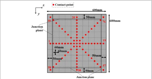
The three linear approximations yielded experimental results for an external force applied at the center of a 100×100×50 mm urethane sponge. Thus, this section presents the linear approximation to a 50-mm-thick ure-thane sponge. There are areas that are not 50 mm thick, such as areas close to the edge of the end-effector. There-fore, the error due to linear approximation was estimated through experimentation for determining the points of action of an external force on Surface 1, as shown in Figure 11. The points of action were set at intervals of 30 mm and numbered from 1 to 76. The points along the
xaxis were numbered 1–19, those along theyaxis were numbered 20–38, those along thexy-axis were numbered 39–57, and those along the−xy-axis were numbered 58– 76. An external force of 15 N was applied in the z-axis direction to these points with a digital push–pull gauge.
Figure 12 shows the error of each linear approxima-tion along thezaxis. The error for the non-compensation case is the distance from the default position to the deformed position on the end-effector. This is the soft material displacement of the end-effector. The average errors obtained for points 1–76 using linear approxima-tions 1, 2, and 3 were 1.7, 3.3, and 4.7 mm, respec-tively. Thus, for the linear approximation experiments, the average error was less than 5.0 mm. No individual error
2 4 6 8 10 12 14 16 18
20 22 24 26 28 30 32 34 36 38
40 42 44 46 48 50 52 54 56
58 60 62 64 66 68 70 72 74 76
0 5 10 15 20 25 30
0 5 10 15 20 25 30
5 10 15 20 25 30
0 5 10 15 20 25 30
0
W/o compensation
Compensation 1 Compensation 2Compensation 3 W/o compensationCompensation 1 Compensation 2Compensation 3
W/o compensation
Compensation 1 Compensation 2Compensation 3 W/o compensationCompensation 1 Compensation 2Compensation 3
Norm
al d
irection
error [
m
m
]
Number
C t t i t b 20 38
Norm
al d
irection
error [
m
m
]
Norm
al d
irection
error [
m
m
]
Norm
al d
irection
error [
m
m
]
Number
C t t i t b 58 76
Number
(a)
Contact point number 1-19Number
(c)
Contact point number 39-57(b)
Contact point number 20-38(d)
Contact point number 58-76Figure 12Experimental results of contact points 1–76.
was greater than 10 mm. The reason for the minimum error when using linear approximation 1 is the increasing external force in the experiment. Due to the mechanical structure of the acrylic frame, it has a property that the deformation increases when a force is applied at the cen-ter of the frame. Since the model assumes that the acrylic frame is composed of a rigid body, the deformation of the frame appears as an error in the experimental results. It seems that for the errors at points 10, 29, 48, and 67, at the center of the end-effector, can be ascribed to the deformation of the acrylic frame. We conclude that linear approximation can be used for estimating soft-material displacement. The next section describes the use of linear approximation 2 for the experiment because it is generally assumed that an external force applied to the end-effector increases as well as decreases.
Whole-body tactile sensing capability with soft material An experiment was conducted for determining the point of action of an external force on five end-effector surfaces.
As shown in Figure 13, the point of action was set at the center of each surface for Surfaces 1–5. Additional points of action were set along the grid at 200-mm increments, thus resulting in a total of nine points per surface. A total of 45 such points were set over the entire end-effector. An external force of 15 N was applied at these points along thez-axis with a digital push–pull gauge. Figure 14 shows three types of average errors for the 45 points. These results were obtained under the following conditions:
(a) End-effector with soft material (urethane sponge), as shown in Figure 13, without compensation for linear approximation;
(b) End-effector with soft material (urethane sponge), as shown in Figure 13, with compensation for linear approximation 2; and
(c) End-effector with highly rigid material (acrylic), as shown in Ref. [12].
Figure 13Points of application of external force.
points of action were set over the entire end-effector and along the grid at 200-mm increments, resulting in nine points per surface. As the dark bars in Figure 14 show, the average errors of these 45 points for (a), (b), and (c) were 27.2, 16.3, and 13.2 mm, respectively. The average error of (a) was larger than that of (c) because end-effector dis-placement was not estimated. For (b), the disdis-placement was estimated by linear approximation. The light bars in Figure 14 show the relative errors by the ratio of absolute error to the size of the end-effector. Since (a) and (b) have 20% larger end-effector, the relative error become smaller in these two cases. The difference between (b) and (c) is quite small in relative error. Therefore, we conclude that whole-body tactile sensing capability with a soft material
10 20 30 40
0 50
absolute error relative error
Urethane sponge End-effector w/o compensation
600 600 550mm
Urethane sponge End-effector with compensation
600 600 550mm
Acrylic End-effector
Ref. [6]
500 500 500mm
A
v
erage absolute
error [mm]
A
v
era
g
e relative
error[%]
1.0 2.0 3.0 4.0
0 5.0
Figure 14Average errors in whole-body tactile sensing capability with soft material and highly rigid material in contact areas.
can be realized by using compensation based on external force and displacement characteristics. Incidentally, there were errors in all cases, i.e., (a), (b), and (c). These errors are unavoidable because commercial force sensors have a maximum of 1% nonlinearity and 1% hysteresis.
Conclusion
This paper proposed a whole-body tactile sensation sys-tem with soft material in the contact areas and a method of compensating for soft material deformation. The error of a calculated contact point with the soft material is sim-ilar to that with a highly rigid material, when the compen-sation for the deformation is introduced. Experimental results verified the validity of the proposed mechanism. Future work will focus on evaluating the compensation for the deformation with other soft materials.
Competing interests
The authors declare that they have no competing interests.
Authors’ contributions
TT drafted the manuscript, participated in the design of the study, and carried out part of the studies. NK carried out the main part of the studies and participated in the design of the study. SS participated in its design and coordination. All authors read and approved the final manuscript.
Acknowledgement
This study was supported in part by a Grant-in-Aid for Scientific Research (C) (24560539).
Received: 14 January 2014 Accepted: 4 July 2014
References
1. Mukai T, Hirano S, Nakashima H, Sakaida Y, Guo S (2011) Realization and safety measures of patient transfer by nursing-care assistant robot riba with tactile sensors. J Robot Mechatron 23(3):360–369
2. Ueki S, Kawasaki H, Ito S, Nishimoto Y, Abe M, Aoki T, Ishigure Y, Ojika T, Mouri T (2012) Development of a hand-assist robot with
multi-degrees-of-freedom for rehabilitation therapy. IEEE ASME Trans Mechatron 17(1):136–146
3. Guidali M, Schlink P, Duschau-Wiche A, Riener R (2011) Online learning and adaptation of patient support during adl training In: Proc. IEEE Int. Conf. on Rehabilitation Robotics
4. Tsuji T, Yamada M, Kaneko Y (2013) A robot measuring upper limb range of motion for rehabilitation database. J Robot Mechatron 25(3):515–520 5. Schmitz A, Maiolino P, Maggiali M, Natale L, Cannata G, Metta G (2011)
Methods and technologies for the implementation of large-scale robot tactile sensors. IEEE Trans Rob 27(3):389–400
6. Ohmura Y, Nagakubo A, Kuniyoshi Y (2006) Conformable and scalable tactile sensor skin for curved surface. In: Proc. IEEE Int. Conf. on Robotics and Automation, pp 1348–1353
7. Tada Y, Inoue M, Kawasaki T, Kawahito Y, Ishiguro H, Suganuma K (2008) A principle and characteristics of a flexible and stretchable tactile sensor based on static electricity phenomenon. J Rob Soc Jpn 26(2):210–216 8. Sato K, Kamiyama K, Kawakami N, Tachi S (2010) Finger-shaped gelforce:
sensor for measuring surface traction fields for robotic hand. IEEE Trans Haptics 3(1):37–47
9. Salisbury J (1984) Interpretation of contact geometries from force measurements. In: Proc. IEEE Int.Conf. on Robotics and Automation, pp 240–247
11. Iwata H, Sugano S (2002) Whole-body covering tactile interface for human robot coordination. In: Proc. IEEE Int. Conf. on Robotics and Automation, pp 3818–3824
12. Tsuji T, Yasuyoshi K, Abe S (2009) Whole-body force sensation by force sensor with shell-shaped end-effector. IEEE Trans Ind Electron 56(5):1375–1382
13. Tsuji T, Ito T (2009) Command recognition by haptic interface on human support robot. In: Proc. IEEE/RSJ Int. Conf. on Intelligent Robots and Systems, pp 3178–3183
14. Arakawa J, Tsuji T, Tan D (2010) Personal identification method for robot with whole-body sensing mechanism. In: Proc. IEEE Int. Conf. on Industrial Electronics, Control and Instrumentation, pp 1590–1595
15. Cervera E, Gracia-Aracil N, Martinez E, Nomdedeu L, Pobil A (2006) Safety for a robot arm moving amidst humans by using panoramic vision. In: Proc. IEEE Int. Conf. on Robotics and Automation, pp 1348–1353 16. Kurita N, Hasunuma H, Sakaino S, Tsuji T (2013) Whole-body tactile
sensing by a force sensor using soft material at contact areas. In: Proc. JSME Robotics and Mechatronics Conference. 2A1-A09. (in Japanese) 17. Kurita N, Hasunuma H, Sakaino S, Tsuji T (2013) Simplified whole-body
tactile sensing system using soft material at contact areas. In: Proc. IEEE Int. Conf. on Industrial Electronics, Control and Instrumentation, pp 4264–4269
18. Lankarani HM, Nikravesh PE (1994) Continuous contact force models for impact analysis in multibody systems. Nonlinear Dynam 5(2):193–207 19. Hayashi M, Sagisaka T, Ishizaka Y, Yoshikai T, Inaba M (2007) Development
of functional whole-body flesh distributed three-axis force sensors to enable close interaction by humanoids. In: Proc. IEEE/RSJ Int. Conf. on Intelligent Robots and Systems, pp 3610–3615
20. Sugiura Y, Kakehi G, Withana A, Lee C, Sakamoto D, Sugimono M, Igarashi T (2011) Detecting shape deformation of soft objects using directional photoreflectivity measurement. In: Proc. ACM Symp. User Interface Software and Technology, pp 509–516
doi:10.1186/s40648-014-0011-x
Cite this article as:Tsujiet al.:Whole-body tactile sensing through a force sensor using soft materials in contact areas.ROBOMECH Journal20141:11.
Submit your manuscript to a
journal and benefi t from:
7Convenient online submission
7Rigorous peer review
7Immediate publication on acceptance
7Open access: articles freely available online
7High visibility within the fi eld
7Retaining the copyright to your article