http://www.sciencepublishinggroup.com/j/ajesa doi: 10.11648/j.ajesa.20190701.13
ISSN: 2376-6069 (Print); ISSN: 2376-6085 (Online)
A Microcontroller Based Intelligent Traffic Control System
Md. Shamsul Arifin
*, Sheikh Alimur Razi, Akramul Haque, Nur Mohammad
Department of Electrical and Electronic Engineering, Chittagong University of Engineering and Technology, Chittagong, Bangladesh
Email address:
*
Corresponding author
To cite this article:
Md. Shamsul Arifin, Sheikh Alimur Razi, Akramul Haque, Nur Mohammad. A Microcontroller Based Intelligent Traffic Control System.
American Journal of Embedded Systems and Applications. Vol. 7, No. 1, 2019, pp. 21-25. doi: 10.11648/j.ajesa.20190701.13
Received: June 26, 2018; Accepted: April 11, 2019; Published: May 9, 2019
Abstract:
A new microcontroller based intelligent traffic control system is proposed in this paper. Instead of changing traffic lights automatically for a given interval, this system allows passing the vehicles considering the number of vehicles on the roads. An Atmega 32 microcontroller and infrared sensors (IR sensors) are used to implement the traffic system. An algorithm is also developed for this purpose. The system is simulated and implemented also by constructing a test rig. The results from the simulation and experimental test rig confirm its appropriateness of using in the roads of different cities. No further processing scheme is required for this intelligent traffic control system.Keywords:
Microcontroller, IR Sensors, Traffic Control System1. Introduction
Traffic control and management system is one of the most important issues for the modern cities in most of the countries. Thereby, in Bangladesh, this issue is becoming vulnerable day by day [1]. In Dhaka city of Bangladesh, a large number of vehicles are moving in different roads every day. Moreover, the number of road vehicles is growing fast in other cities of Bangladesh like Chittagong, Khulna, Rajshahi etc.
In contrast to this infrastructure growth is slow as compared to the growth in number of vehicles because of space and cost constraints. Additionally, traffic system in Bangladesh is non-lane based and chaotic. Moreover, the pedestrian cross the road and move through the road very unconsciously. However lacking of a pedestrian friendly smart traffic system and manual management system encourage them to be more unconscious regarding the traffic safety. Every year a number of people died in road accident. However a lot of road accident occur due to manual management of traffic system i.e. managing the road crossing with the help of a traffic police. A smart and cost effective traffic control system is therefore necessary for the cities of Bangladesh.
On the contrary, the traffic system of North America and Europe are more organized and lane based most of the time. The infrastructure is also appropriate to support the traffic of the cities. In some part of these countries, the pedestrians are allowed to pass after applying to cross the road by pressing a switch. Although
everything is quite well, significant amount of accident occurs due to not obeying traffic signal. So design a robust and pedestrian friendly traffic management is essential for all of us.
Typically traffic systems operate on a timing mechanism that turns on the lights after a given time interval. The classical system uses weight as a trigger mechanism [2]. For these types of systems, the traffic police or operator has no option to control the system if any emergency situation occurs. Additionally, the classical system has no intelligence. That is why; the system itself cannot contribute for managing the vehicles to move efficiently [1-2].
In recent years, significant amount of work has been done to relate the traffic system and modern technologies. Various systems uses RFID and GSM module to transmit data and communicate with specific vehicles [3-4]. Specific software and algorithm is also developed to manage vehicles in roads and smart phones are also incorporated in this regard [5–7]. Image processing and face detection technologies are also incorporated to manage the system more effectively [8].
Additionally, fuzzy logic has become popular at the present time as it is based on simple mathematics and it works more accurately. Another vital advantages of fuzzy system is it is easy to implement. Fuzzy logic control is widely use in power system control, converter designing, aerospace controlling etc [9-15]. That’s why, some researchers is also trying to improve the traffic system using neural network, fuzzy logic etc. [9-11].
Although several works has been done to manage the traffic system, however the major task is to implement and to manage the cost. Thereby, these are not appropriate for most of the developing countries like Bangladesh.
In this paper a smart automatic traffic control system is proposed. In this system can take decision considering the number of vehicles in a road. It takes samples after a given time interval and allows the traffic lights to stay on sequentially so that the busiest roads gets the first priority. Infrared based transmitter and receiver are used here as sensors. An Atmega 32 microcontroller is used to manage the operations of the total system. An algorithm is also developed for the system, which is loaded in the microcontroller. The control scheme is easy to implement and to manage.
This paper is organized as follows. In section II, presents the basic block diagram and describes the interconnections among the components of the systems. Section III describes the individual units of the systems. In Section IV the operation of the system is described. The simulation result and implementation is described in section V. Finally, in
section VI, a conclusion is drawn.
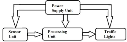
2. Block Diagram of the System
Figure 1 shows a typical block diagram of the traffic control system. The total system consists of four units like the power supply unit, the sensor unit, the processor unit and the display unit. The power supply unit gives uninterrupted power to the other units of the system. The sensor unit gives the data to processor unit to process data and based on the data, the processor unit gives necessary instructions on display unit. The display unit shows desired output.
3. The Proposed Traffic Control System
The total system can be divided into several units. The structure and tasks of these units are illustrated in following subsections.
3.1. Power Supply Unit
This unit consists of a 220/9 volt transformer, a bridge rectifier and a generic integrated circuit for regulated power supply. At first using the transformer the voltage level is altered to 9 Volt. Then the rectifier is used to convert the AC signal to DC and at last stage Integrated circuit IC 7805 is used to produce regulated 5 Volt. The circuit diagram of this unit is given in figure 2.
Figure 2. Circuit diagram of power supply unit.
However this power supply unit is designed to drive the experimental prototype. For the practical system it is necessary to get support from the power distribution network so that the traffic light can operate. Additionally, this sort of power supply unit is also required to operate the control switches.
3.2. Sensor Unit
The sensor unit consists of an Infrared transmitter and an infrared receiver. The connection diagram of this unit is presented in figure 3. The resistors connected here ensures proper biasing. When the transmitted signal is received the receiver transmits zero to microcontroller and vice versa.
This mechanism is applied to detect the presence of cars.
3.3. Processor Unit
The processor unit consists of an Atmega 32 microcontroller. Port C &D are used to make connections of traffic lights. Port A is used to make connections of sensors.
3.4. Display Unit
The display unit consists of traffic lights. Figure 4 shows a typical component of the display unit.
Figure 4. Circuit diagram of display unit.
4. Operation of the Proposed System
The proposed traffic system operates considering the number of vehicles in a road. Figure 5 shows the typical connection of four roads. In each road, equal numbers of sensors (S1 to S8) are connected for actuating the number of vehicles at a specific time. When there is no vehicle in front of the sensors the sensors detects no obstacle. As a result it transmits high signal (logic 1) to the microcontroller. On the other hand, low signal (logic 0) is transmitted if any vehicles are detected by sensors.
Figure 5. Arrangements of traffic lights on road.
All the signals transmitted by sensors are received by the microcontroller. A program is loaded in the microcontroller to detect the road with maximum vehicles. Thereby considering this number of vehicles, the road having maximum number of vehicles is cleared first by giving green signal to corresponding road. Then the road having second maximum vehicles is cleared in a similar way and so on. The interval of giving green signal to each road is same. When
green signal is given to a specific road to pass the vehicles the other three roads is stopped by giving red signal.
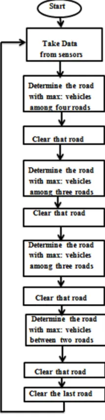
The flow chart given in figure 6 better describes the algorithm of the proposed traffic system. According to the flow chart the road having maximum vehicles are determined and cleared first. Then among the rest of three roads, the road having maximum vehicles is determined again and cleared then. In this way the algorithm proceeds.
Figure 6. Flow chart of the system.
5. Results and Discussions
5.1. Simulation Results
5.2. Experimental Results
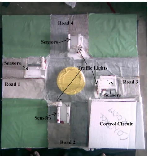
The proposed traffic system and the developed algorithm has implemented in a test rig as shown in Figure 8. To implement this test rig the LEDs of different colors are considered as the traffic lights and IR transmitter and receivers are used as sensors. An Atmega 32 microcontroller is used as a processor unit. The program is written
considering different situation of the road and possible decision is also included in the program depending on the respective situation. Then the program is loaded in the microcontroller.
Like the simulation here the vehicle passing time is considered as 5 second and one second transition time. The data are taken from sensors for consideration after every 24 seconds. From the test rig, desired output is obtained.
Figure 7. Simulation model of the proposed system.
Figure 8. Implementation of the system.
6. Conclusion
The main objective of this project work is to develop a cost-effective and intelligent vehicle traffic control system to manage the vehicles moving in different roads. The results from the simulation and experimental test rig validate its applicability for Dhaka and other cities of Bangladesh. However it can be used smoothly to the cities of other countries also. The system consists of a microcontroller embedded with the control algorithm. The algorithm decides about the vehicles numbers from sensor data and takes necessary decision to clear the road effectively.
The numerical values used for the programming can be changed considering the requirements of the roads, cities, vehicles and the system. This flexibility makes the system effective to achieve maximum saving.
References
[1] M. S. Arifin, M. R. Palash, M. I. Khalil, M. M. S. Khan, and M. H. Haque, “A Microcontroller Based Smart Traffic System” GUB J. Sci. Eng., vol. 2, no. 1, pp. 40–44, 2015.
[2] W. Sun and K. C. Mouskos, “Network-wide traffic responsive signal control in urban environments,” in Joint Conference on Information Sciences, pp. 734–737,2000.
[3] R. Sundar, S. Hebbar, and V. Golla, “Implementing intelligent traffic control system for congestion control, ambulance clearance, and stolen vehicle detection,” IEEE Sens. J., vol. 15, no. 2, pp. 1109–1113, 2015.
[4] A. Patnaik, V. Natarajan, B. Karthikeyan, and P. Surendran, “Automatic traffic control system for single lane tunnels,” 2014 Int. Conf. Adv. Electr. Eng. ICAEE 2014, pp. 1–4, 2014.
[5] A. Goel, S. Ray, and S. Chandra, “Intelligent Traffic Light System to Prioritized Emergency Purpose Vechicles based on Wireless Sensor Network,” Int. J. Comput. Appl. 2012.
[6] P. Shih, C. Tsai, and C. Hsu, “An Efficient Automatic Traffic Sign Detection and Recognition Method for Smartphones,” in 10th International Congress on Image and Signal Processing, BioMedical Engineering and Informatics (CISP-BMEI 2017), pp. 1–5, 2017.
[7] S. Kong, F. Application, and P. Data, “Methods and Software for Managing Vehicle Priority in a Self-Organizing Traffic Control System,” US 9,536,427 B2, 2017.
[8] C. O. Manlises, J. M. Martinez, J. L. Belenzo, C. K. Perez, and M. K. T. A. Postrero, “Proc. Real-time integrated CCTV using face and pedestrian detection image processing
algorithm for automatic traffic light transitions,” in International Conference on Humanoid, Nanotechnology, Information Technology, Communication and Control, Environment and Management (HNICEM), pp. 1–4, December 2015.
[9] J. Favilla, A. Machion, and F. Gomide, “Fuzzy traffic control: adaptive strategies,” in Second IEEE International Conference on Fuzzy Systems, pp. 506–511, 1993.
[10] G. Kulkarni and P. Waingankar, “Fuzzy logic based traffic light controller,” in International conference on Industrial and information systems, (ICIIS), 2007, pp. 107–110.
[11] Y. Bi, X. Lu, D. Srinivasan, Z. Sun, and Z. Sun, “Optimal Type-2 Fuzzy System For Arterial Traffic Signal Control,” IEEE Trans. Intell. Transp. Syst., pp. 1–19, 2017.
[12] Sousa, Gilberto CD, Bimal K. Bose, and John G. Cleland. "Fuzzy logic based on-line efficiency optimization control of an indirect vector-controlled induction motor drive." IEEE Transactions on Industrial Electronics Vol: 42, No. 2 pp: 192-198, 1995.
[13] Wing-Chi, Chi K. Tse, and Yim-Shu Lee. "Development of a fuzzy logic controller for DC/DC converters: design, computer simulation, and experimental evaluation." IEEE Trans. on Power Electronics, Vol: 11, No. 1, pp: 24-32. 1996.
[14] Simoes, M. Godoy, Bimal K. Bose, and Ronald J. Spiegel. "Fuzzy logic based intelligent control of a variable speed cage machine wind generation system." IEEE transactions on power electronics Vol: 12, No. 1, pp: 87-95, 1997.