University of Pennsylvania
ScholarlyCommons
Publicly Accessible Penn Dissertations
1-1-2016
Scaled Autonomy for Networked Humanoids
Stephen Gerald Mcgill
University of Pennsylvania, [email protected]
Follow this and additional works at:
http://repository.upenn.edu/edissertations
Part of the
Robotics Commons
This paper is posted at ScholarlyCommons.http://repository.upenn.edu/edissertations/1888 For more information, please [email protected].
Recommended Citation
Scaled Autonomy for Networked Humanoids
Abstract
Humanoid robots have been developed with the intention of aiding in environments designed for humans. As such, the control of humanoid morphology and effectiveness of human robot interaction form the two principal research issues for deploying these robots in the real world. In this thesis work, the issue of
humanoid control is coupled with human robot interaction under the framework of scaled autonomy, where the human and robot exchange levels of control depending on the environment and task at hand. This scaled autonomy is approached with control algorithms for reactive stabilization of human commands and planned trajectories that encode semantically meaningful motion preferences in a sequential convex optimization framework.
The control and planning algorithms have been extensively tested in the field for robustness and system verification. The RoboCup competition provides a benchmark competition for autonomous agents that are trained with a human supervisor. The kid-sized and adult-sized humanoid robots coordinate over a noisy network in a known environment with adversarial opponents, and the software and routines in this work allowed for five consecutive championships. Furthermore, the motion planning and user interfaces developed in the work have been tested in the noisy network of the DARPA Robotics Challenge (DRC) Trials and Finals in an unknown environment.
Overall, the ability to extend simplified locomotion models to aid in semi-autonomous manipulation allows untrained humans to operate complex, high dimensional robots. This represents another step in the path to deploying humanoids in the real world, based on the low dimensional motion abstractions and proven performance in real world tasks like RoboCup and the DRC.
Degree Type
Dissertation
Degree Name
Doctor of Philosophy (PhD)
Graduate Group
Electrical & Systems Engineering
First Advisor
Daniel D. Lee
Keywords
Humanoids
Subject Categories
SCALED AUTONOMY FOR NETWORKED HUMANOIDS
Stephen Gerald McGill, Jr.
A DISSERTATION
in
Electrical and Systems Engineering
Presented to the Faculties of the University of Pennsylvania
in
Partial Fulfillment of the Requirements for the
Degree of Doctor of Philosophy
2016
Supervisor of Dissertation
Daniel D. Lee
Professor of Electrical and Systems Engineering
Graduate Group Chairperson
Alejandro Ribeiro
Professor of Electrical and Systems Engineering
Dissertation Committee
George J. Pappas, Professor of Electrical and Systems Engineering
Youngmoo Kim, Associate Professor of Electrical and Computer Engineering Drexel University
SCALED AUTONOMY FOR NETWORKED HUMANOIDS
COPYRIGHT
2016
Stephen Gerald McGill, Jr.
This work is licensed under the
Acknowledgements
My advisor Daniel Lee provided a challenging and inspirational atmosphere in his lab, entrenching
me in the mindset of experimental validation and real world system robustness. The opportunities
for growing in leadership roles within RoboCup and the DARPA Robotics Challenge have proven
invaluable. His constant focus on approaches to and presentation of scientific research has forever
changed my thinking. My experience with Dr. Lee will serve me well throughout my professional
career.
To Daniele Nardi, I am grateful for his hospitality and guidance through my research time with
him at Sapienza University of Rome and the fruitful discussions on benchmarking, human interfaces
and robotics. I would like to thank Dennis Hong for the relationships built at Virginia Tech and
UCLA and his confidence in our joint research over many years and the unique perspective on
successful projects. I am thankful for Youngmoo Kim’s support and personable mentorship that
were never far away at Drexel. To George Pappas, I am grateful for his invaluable advice through
this process in both office and hallway conversations. The guidance of my committee members is
truly appreciated.
Seung-Joon Yi contributed to my lab research, and through the yearly competitions in RoboCup
and the DARPA Robotics Challenge, we dealt with the stressful situations in stride and built a great
friendship in the process. To Larry Vadakedathu for all of the mechanical work and support in team
management. For Yida Zhang and Karen He for the invaluable software work and team focused
attitude over the years. As the new members of our lab, Bhoram, Jinwook, Heejin and Daewon
bring a wonderful breathe of fresh air and good friendships.
- doctoral work no exception. My brothers Will and Nick have provided insightful feedback time
after time, with encouragement and competitive drive through many adventures. My parents Steve
and Claire are the most supportive, selfless pair on the planet whom I find to be my foremost role
models. There is no way that I could have completed any of this work without their counseling
family environment.
The work that has been accomplished through my PhD career has been supported by the
Of-fice of Naval Research (ONR) under grants N00013-11-1-0078 and SAFFiR N00014-11-1-0074,
the National Science Foundation (NSF) PIRE program under OISE-0730206, and the Defense
Advanced Research Projects Agency (DARPA) through grant N65236-12-1-1002 in the DARPA
Robotics Challenge. Additional support through the University of Pennsylvania’s Ashton
Fellow-ship and the EU Erasmus Mundus’ Transatlantic PartnerFellow-ship for Excellence in Engineering program
between Sapienza University of Rome and the University of Pennsylvania.
The amazing people throughout the School of Engineering and Applied Science brought me
cherished relationships and experiences. In particular, the staff in ESE, MBO, RAS as well as the
tremendous leadership from the Dean’s office have been tremendously supportive. The faculty, staff,
and students in the GRASP lab over the years provided a fantastic intellectual environment and I
ABSTRACT
SCALED AUTONOMY FOR NETWORKED HUMANOIDS
Stephen G. McGill, Jr.
Daniel D. Lee
Humanoid robots have been developed with the intention of aiding in environments designed
for humans. As such, the control of humanoid morphology and effectiveness of human robot
in-teraction form the two principal research issues for deploying these robots in the real world. In
this thesis work, the issue of humanoid control is coupled with human robot interaction under the
framework of scaled autonomy, where the human and robot exchange levels of control depending
on the environment and task at hand. This scaled autonomy is approached with control algorithms
for reactive stabilization of human commands and planned trajectories that encode semantically
meaningful motion preferences in a sequential convex optimization framework.
The control and planning algorithms have been extensively tested in the field for robustness and
system verification. The RoboCup competition provides a benchmark competition for autonomous
agents that are trained with a human supervisor. The kid-sized and adult-sized humanoid robots
co-ordinate over a noisy network in a known environment with adversarial opponents, and the software
and routines in this work allowed for five consecutive championships. Furthermore, the motion
planning and user interfaces developed in the work have been tested in the noisy network of the
DARPA Robotics Challenge (DRC) Trials and Finals in an unknown environment.
Overall, the ability to extend simplified locomotion models to aid in semi-autonomous
ma-nipulation allows untrained humans to operate complex, high dimensional robots. This represents
another step in the path to deploying humanoids in the real world, based on the low dimensional
Contents
1 Introduction 1
1.1 Motivation and Evaluation . . . 2
1.1.1 Contributions . . . 3
1.1.2 RoboCup and Field Robotics . . . 4
1.2 Hardware . . . 6
1.2.1 Humanoid Platform . . . 6
1.2.2 Sensors and Actuators . . . 12
1.2.3 Power and Computation . . . 17
1.2.4 End Effectors . . . 19
1.3 Software Architecture . . . 22
1.3.1 Hierarchical Behaviors . . . 24
1.3.2 User Interfaces . . . 30
2 Humanoid Motion Models 34 2.1 Representations and Planning . . . 34
2.1.1 Function Approximation . . . 35
2.1.2 Trajectory Planners . . . 36
2.1.3 Task Parameterization . . . 37
2.1.4 Dimensionality Reduction Techniques . . . 38
2.1.5 Sequential Low Dimensional Structures . . . 44
2.2.1 Regressions and Segmentation . . . 47
2.2.2 Inverse Optimal Control . . . 49
2.2.3 Low Dimensional Optimization . . . 49
2.2.4 Human Interface . . . 50
3 Dynamics and Scaled Autonomy 53 3.1 Coordinated Manipulation . . . 54
3.1.1 Alignment Strategies . . . 55
3.1.2 Grasping Strategies . . . 57
3.1.3 Performance . . . 57
3.2 Locomotion Synchronization . . . 58
3.2.1 Footstep Planning . . . 59
3.2.2 Proportional Distance Control . . . 60
3.2.3 Stability Metrics . . . 60
3.2.4 Performance . . . 60
3.3 Real-time Imitation of Human Motion . . . 63
3.3.1 Kinematic Retargeting . . . 64
3.3.2 Simplified Dynamics Model . . . 66
3.3.3 Real-time Stabilization . . . 67
3.3.4 Performance . . . 72
3.4 Bimanual Manipulation . . . 72
3.4.1 Task-based Coupled Motion . . . 75
3.4.2 Performance . . . 76
4 Human Preferences for Optimization 80 4.1 Problem Formulation . . . 80
4.1.1 Human Preferences . . . 82
4.1.2 Anytime Refinement . . . 82
4.2.1 Inverse Kinematics Optimization . . . 84
4.2.2 Jacobian Task Space Controller . . . 85
4.3 Dimensionality Reduction . . . 86
4.3.1 Basis Filtering . . . 87
4.3.2 Singularities . . . 89
4.4 Learning User Preferences . . . 89
4.4.1 Interaction . . . 90
4.4.2 Difference Formulation . . . 92
4.4.3 Loss Function . . . 93
4.4.4 Multiple User Preferences . . . 96
4.5 Supervised Perception . . . 96
4.5.1 Assisted Visual Servoing . . . 98
4.5.2 Object Detection . . . 99
4.5.3 Constrained Segmentation . . . 103
4.6 Results and Future Work . . . 105
4.6.1 Planning Performance . . . 106
4.6.2 Learning Performance . . . 107
4.6.3 Perception Performance . . . 110
4.6.4 Future Interface Design . . . 111
5 DARPA Robotics Challenge 115 5.1 Upper Body Control . . . 118
5.1.1 Task Level Arm Control . . . 118
5.1.2 Preliminary Arm Planner . . . 120
5.1.3 Optimizing Arm Planner . . . 121
5.1.4 Torso Movement Compensation . . . 123
5.2 Degraded Human Communication . . . 126
5.2.2 Communication Architecture . . . 131
5.2.3 Perception Interaction . . . 136
5.2.4 Motion Interaction . . . 138
5.3 Performance . . . 138
5.3.1 DRC Trials Tasks . . . 140
5.3.2 DRC Finals Tasks . . . 148
5.3.3 Network Usage . . . 156
5.3.4 Lessons Learned . . . 158
List of Tables
1.1 Specifications comparison of Track A and B robots at DRC Trials 2013 . . . 9
1.2 Actuator specifications of THOR-OP joints . . . 12
3.1 Number of successful trials for imitating different upper body motions. . . 73
3.2 User error in distance for manipulation alignment. . . 78
3.3 User error in angle for manipulation alignment . . . 78
3.4 User time to completion for manipulation alignment . . . 78
4.1 Motion Configuration Preferences . . . 82
5.1 Settings for transmitting perception data to operators . . . 129
5.2 DRC Trials Performance of Team THOR . . . 140
List of Figures
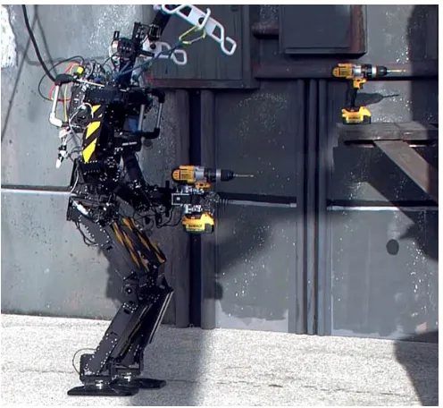
1.1 The THOR-OP robot approaching the wall to break while holding a drill in its hand. 5 1.2 DARwIn-OP robot and its dimensions represent a miniaturized humanoid robot for
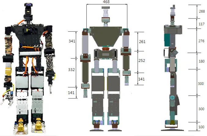
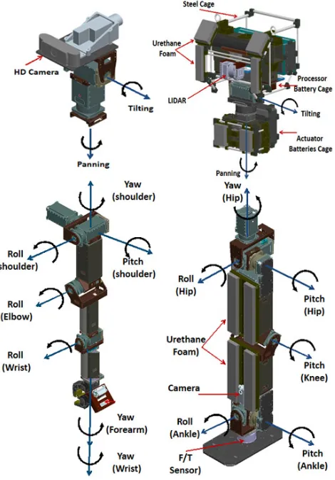
development. . . 7 1.3 THOR-RD robot and its dimensions (in millimeters) . . . 8 1.4 The structural components for a single THOR-OP robot use standardized dimensions. 10 1.5 Kinematic configuration of THOR-OP . . . 11 1.6 Three different arm configurations evolved during development of the THOR-OP. . 13 1.7 (a) The gripper for the DRC Trials consisted of two under actuated fingers to wrap
around an object, and a rigid palm to give support. (b) The underactuated mecha-nism in the finger. . . 14 1.8 The overall structure of the THOR-OP hardware interconnections includes four
in-dependent motor communication buses. . . 15 1.9 The transparent view of the Dynamixel Pro modular actuator we use for the
THOR-OP robot. . . 16 1.10 CPU utilization of the various processes running onboard the robot. Computation
fluctuated during walking phases and arm planning routines. . . 17 1.11 The power consumption varies during different phases of a locomotion cycle. The
top shows when THOR-OP is taking a large step over a threshold of 2.5in high, while the bottom represents walking in place. (DS: double support,LS: left support,
RS: right support.) . . . 18 1.12 The iterations of gripper design. (a) Two fingered gripper with a fixed palm. (b)
Modular 3 fingered gripper. (c) Final version with a slim profile to minimize self collision. . . 20 1.13 Foot designs suggested for the THOR-RD robot. (a) Stock THOR-OP foot (b)
Pro-totype foot with wide support area and internal damper. (c) Large sized foot made of carbon fiber to reduce weight. (d) Stock THOR-RD foot. (e) Adjustable foot with bolt on supports. . . 21 1.14 The flexible software leads to various supported humanoid robotic platforms. Top,
from left: THOR-RD, DARwIn-OP, Aldebaran Nao. Bottom, from left: Simulated ATLAS, DARwIn-HP, Mini-HUBO, DARwIn-LC. . . 23 1.15 Block Diagram of the Software Architecture. . . 24 1.16 The software architecture centers around shared memory . . . 25 1.17 Teamplay is simulated using Webots to rapidly prototype behaviors that perform
1.19 The motion diagram shows how humanoid steps are planned. . . 29 1.20 The system architecture is divided into low level drivers (boxed in red) that interface
with separate Motion and Perception systems. At the highest level, finite state ma-chines direct behavior based on these systems, communicating over shared memory and a message passing system. . . 30 1.21 A tablet interface can command and display simple streams of information.During
the DRC Trials, the visual systems during the driving task was commanded via iPad. 31 1.22 Virtual car parts provide a structured model of interaction . . . 32 1.23 The user interface provides a variety of perception cues, which includes the current
configuration of the robot (shown in grey rendering), the target configuration of the robot (shown in green rendering), 2D obstacles (shown in vertical rods), 3D mesh and high and low bandwidth video feeds. . . 32
3.1 Two DARwIn-OP humanoid robots and carry a stretcher. . . 55 3.2 Images are segmented based upon color. Top, DARwIn-OP’s blue eyes are
seg-mented and recognized as circles. Bottom, the stretcher is recognized as two long color blobs. . . 56 3.3 Both coupled humanoid systems and quadruped robots share similar configurations.
Pairs of legs are connected via a rigid object or spine . . . 58 3.4 The footstep touchdowns over time. The top waveform is the first robot’s foot steps,
while the bottom waveform is the second robot’s footsteps. . . 59 3.5 Over time, the gaits synchronized to within a hundredth of a second to desired phase
offset. This is a tolerance of about 3%. . . 61 3.6 Squared and absolute deviations for measuring stability. Dashed line represents
stability in thex direction, normal line represents stability in the ydirection, and thick dashed/dotted is the sum of these stabilities. . . 62 3.7 Stabilizing a robot in realtime requires a tracking system with networking and
hu-manoid control, diagrammed here. . . 63 3.8 Left: Joint IDs assigned to the physical DARwIn-OP. Right: Kinematic model of
the DARwIn-OP . . . 64 3.9 The extended LIPM with two additional arm masses. . . 66 3.10 Three push recovery strategies. (a) Ankle strategy that applies a control torque at
the ankle joint. (b) Hip strategy which uses the angular acceleration of the torso and limbs to apply counteractive ground reaction forces. (c) Step strategy that changes the support point by stepping. . . 68 3.11 The DARwIn-OP robot imitating the full body behavior of human operator in real
time . . . 68 3.12 Stability regions for each push recovery controller. White and gray region denotes
stable and unstable region of state space. Black and red lines denote stable and unstable state trajectories from various initial states. . . 71 3.13 The real-time imitation of various full-body human motions by the DARwIn-OP
robot. . . 73 3.14 Novice users are able to quickly grab a steering wheel without prior training. . . . 74 3.15 Above, human interface for configuring constraints for teleoperation. Below, one
4.1 The human preference optimization allowed for quick upper body planning of the THOR-RD robot during the DRC Finals. . . 81 4.2 In obstacle laden situations, preferences help the operator to keep the arm tucked
without modeling the environment. . . 83 4.3 Some initial trajectories require joint interpolation since the Jacobian controller
times out. The straight lines at the end of the trajectories show how the controller switches. . . 87 4.4 The optimization routine is able to smooth out the trajectory, even if two different
controllers were used in generation. . . 88 4.5 Above, the THOR-RD robot plans a path with the elbow protruding out with high
manipulability in the middle of the joint range. Below, the robot plans a path with the elbow tucked in for maneuvering in tight spaces. The target transform for both paths is the same. . . 89 4.6 Motion planning for grabbing a drill requires motor axes to be aligned for gravity,
while door opening requires tucked arms that do not collide with the door jamb. Valve turning and hose connecting require less restrictions. These planning prefer-ences can be learned from human interaction. . . 91 4.7 The human interface provides an animation of the trajectories. These animations
can be edited by the user to provide interaction cues that form a loss function. . . . 92 4.8 The user intervenes in the pathξ†at timesti marked with vertical lines to generate
interventionsξ†(ti). The maximum joint space change is around 25 degrees in this
example path. . . 93 4.9 The task space is minimally affected from user interactions. The maximum changes
are about 3cm and 6 degrees in this example . . . 94 4.10 The user interactions imply a high trust for the immediate re-planned path, but high
dislike for the recent path. Here,β =1 . . . 95 4.11 Infrared camera readings on a shipboard environment. (a) Infrared images do not
saturate under normal conditions. (b) In high heat environments, saturation makes image processing more difficult. . . 97 4.12 The YouBot is outfitted with scissors to cut a variety of cables. . . 99 4.13 The graphical user interface for eliciting user visual preferences can be accessed
through a tablet (a.) or desktop web browser (b.) . . . 100 4.14 The image on the left shows the lines detected in the color channel of highest
vari-ance. The right image highlights the edges in the image. . . 101 4.15 The Radon space image, shown on the left, shows the votes for lines in an image.
Nearby parallel lines signify a wire, shown on the right, from a zoom-in of the left Radon image. . . 102 4.16 Colortables are made with a QT user interface for classifying ball colors (left). The
generated lookup table can be monitored in real time in MATLAB (right). . . 104 4.17 Automatic plane detection from LIDAR scans for localization. . . 105 4.18 The RRT∗planner has unpredictable task space motion (top). Through the
4.19 The preference based planner establishes a predictable motion in task space during initial generation (top) that is further optimized (bottom). Each line represents one dimension in task space. . . 109 4.20 The human user is shown scenes from the DARPA Robotics Challenge Finals in
order to teach the best trajectory preferences. . . 110 4.21 The Valve pose should keep the arm near the center of the joint limits, the Door arm
pose should avoid extending its elbow and the Drill configuration should align with the gravity vector. . . 110 4.22 Semi-autonomous selection of the footstep positions. (a) Original RGBD data. (b)
An autonomous segmentation of steppable surfaces. (c) The human augmented admissible foot landing positions selected by operator. . . 111 4.23 During the DRC Trials, the operator would command the robot to complete the
valve task based on experience, disallowing the robot to chose its own policies. . . 112 4.24 A probabilistic scenario allows the robot to act autonomously, and receive updates
from a human for replanning. Here, given a command to turn the yellow valve, the probabilities are updated. . . 114
5.1 THOR-RD enters the indoor environment after opening the door in the DRC Finals. 117 5.2 The multiple phases of the loaded door opening task . . . 119 5.3 Arm configurations can overload the arm when too much torque is expected from
the 20W motors. Here, the wrist motor sags significantly due to the weight of the drill. . . 122 5.4 Two cases requiring human preferences for arm planning: (a) tucked arm stances
are required for obstacle laden situations and (b) poor arm configurations can lead to thermal shutdown of actuators when holding heavy objects. . . 123 5.5 The two different arm motions for the door and valve tasks at DRC Finals Competition.123 5.6 3D constructions provided from the LIDAR with different settings. (a) Fast mesh
(b) Slow mesh . . . 125 5.7 The quasi-static full body balancing control moved the torso significantly to offset
the weight of the arms. . . 125 5.8 The operator interface setup included three main screens for the user to guide the
robot and observe its environment. . . 126 5.9 The system layout for the operator interface allowed multiple machines to be used
simultaneously. . . 127 5.10 Multiple cameras provided different perspectives for manipulations. (a) Head
cam-era (b) Hand camcam-era . . . 128 5.11 A secondary camera helps overcome the poor depth perception of the main camera.
(a) Third person view. (b) The main camera feed. (c) Secondary camera feed on high bandwidth channel. (d) Secondary camera feed on low bandwidth channel. . . 130 5.12 During the Finals, tens and hundreds of kilobytes of data during one second network
openings over the high bandwidth link for camera and depth data, respectively. . . 134 5.13 Feedback packets (a) were sent at three different rates, depending on how the
5.15 THOR-OP at the 2013 DRC Trials performing four of five tasks in which it scored points. . . 139 5.16 THOR-OP used hook to hold and rotate the handle for door task. A nearly 80
degree was required to open the door which was unexpected and harder than our testing setup which only required 60 degree. . . 143 5.17 THOR-OP successfully approached to the table and got grasp of the drill. The upper
finger was actually pressing the trigger of the drill at the moment shown in figure above. . . 144 5.18 THOR-OP was almost there to touch the wye with the hose head and score the 2nd
point when the power cable for the left wrist popped out. The forearm drooped down but the gripper was able to keep a good grip of the hose. . . 145 5.19 THOR-OP taking a step on the cinder blocks. . . 147 5.20 THOR-OP successfully scored a point in the ladder task. . . 148 5.21 THOR-RD drives the vehicle with its head rotated 180 degrees. Due to the default
birdwalk knee configuration, the robot is mounted backwards in the car. . . 149 5.22 The high and low bandwidth view during the DRC Finals Valve task: The robust
passive hand allows for quick alignment, and the low resolution image feed provides an immediate feedback during operation. . . 150 5.23 The operator guides THOR-RD through the doorway with the help of LIDAR
feed-back over the low bandwidth channel. . . 151 5.24 The robot pulls the plug out of the socket and mounts it in the other socket during
the DRC Testbed. . . 154 5.25 The THOR-RD robot traverses over the DRC Finals uneven terrain in a simulated
environment. . . 154 5.26 The THOR-RD robot climbing a set of stairs using the toe and heel lift controller. . 155 5.27 Network usage for picking of the drill during poor network conditions, with a five
second moving average. . . 156 5.28 Operator command rates slowed down upon transitioning from the outdoor network
conditions to indoor conditions. . . 157 5.29 Comparison of operator command rate between indoor and outdoor situations. . . . 157 5.30 (a) THOR-RD robot falls down after stepping on the surface irregularities. (b) Close
Chapter 1
Introduction
Humanoids represent the quintessential high dimensional robotic system, composed of two
kine-matic chains that represent legs and two chains that represent arms. Representing the human form,
they are ideal systems for dynamic locomotion and manipulation tasks use in human environments
and present an intuitive form for operators. Unfortunately, humanoids are susceptible to losing
bal-ance and their kinematic chains pose a challenging high dimensional planning problem for control.
While they represent the human morphology, these robots cannot mimic human motion exactly due
to kinematic and dynamic differences. With planning and retargeting challenges, both autonomous
planners and human teleoperation remain cumbersome, slow and suboptimal.
Physically motivated models of humanoids can abstract the kinematic chain properties into
sim-ple inverted pendulum dynamical equations of motion. These models help to keep humanoids stable,
but disallow complicated motions. On the other end of the spectrum, model-less motion trajectories
allow rich motions, but afford no way to stabilize the humanoid from falling. This work seeks to
es-tablish a middle ground, where models can inform complex motion planners of stability constraints
and human operators can inform planners of complex motion preferences. Of note, this work with
focus on methods for technically representing the human intent encoding for the robot to plan
mo-tions. Simple interfaces for human operator are provided, with research into optimal interfaces and
1.1
Motivation and Evaluation
Walk controllers that rely on model based abstractions allow a number of independent parameters,
such as step height and cadence, to be tuned for optimal performance. Trained engineers find such
parameters very useful and understandable when tuning the walk engine for new robots or new
terrains. These parameters provide a low dimensional space that controls the dynamic motions of
robots with over 20 degrees of freedom. However, these parameters are determined using linear
inverted pendulum (LIP) models to represent humanoid walking motions. Optimal control of
sim-plified models like LIP and spring loaded inverted pendulum models have attained success in many
walking engines [34], [63], [149]. Current research into optimal control has led to convex
optimiza-tion problem formulaoptimiza-tions [32], [122] that effectively solve planning problems in the control loop
window. However, to set up a new dynamic motion, such as swinging its arms in a dynamic way,
a whole new physical model is required. The effects of the arm motions are then determined after
solving systems of dynamic equations.
Because model based techniques have this fundamental drawback, mapping human input
di-rectly to trajectory generation can be a good technique for complicated motions. The popular
dy-namic motor primitives approach [54] allows users to provide a set of example trajectories, via
kinesthetic teaching or motion capture techniques, and the motor primitive system will find a
ref-erence trajectory using locally weighted regression [6]. Teleoperation of trajectories of humanoids
ranges from direct joint control that involves some level of kinematic retargeting [36], [114] to task
based abstractions [161]. The reference trajectory, however, is of the same dimension of the robot
joint space, or possibly the task space. While a set of dependent structures within this joint space
trajectory can be found, it is unclear if these dependent structures can be conveyed meaningfully to
a human user.
The high dimensionality of the reference trajectory and the learned examples means that
mod-ification and understanding of the motions is difficult. Solving for optimal trajectories in a high
dimensional state space means encountering the curse of dimensionality where computation and
subspace that captures the essence of the example trajectories can make the optimization problem
more tractable. To decompose the example trajectories into a low dimensional space, the animation
and planning problem is viewed from optimal control and motion classification viewpoints [129],
[143]. When describing optimization problems, appropriate cost functions in the original state space
abound, including effort, energy, maximum torque, and more; they offer engineers an artistic
out-let to craft behaviors. My work includes an optimization formulation that includes human input to
generate complicated motions that prior motion planners would not be able to accomplish.
Finally, the ultimate goal of humanoid robotics is to work in typical environments designed for
humans. Until very recently, most humanoid robotics research focused on small subsets of that
goal, such as walk control, human robot interaction or stationary manipulation in well controlled
laboratory environments. Attempts to build a complete, robust, remotely operated humanoid robot
system for practical tasks have been deterred mainly due to the steep hardware costs as well as the
risks associated with operating an intrinsically unstable humanoid in uncontrolled environments.
Thus it is critical to test approaches to humanoid robotics in the real world with a focus on robust
software and hardware systems, augmented with development of user interfaces for motion feedback
and planning.
1.1.1 Contributions
The contributions of this thesis focus on allowing humanoid robots, whose high level models are
described in Chapter 2, to act in semi-autonomous ways. First, in Chapter 3, the dynamics of
humanoid robots are considered when allowing a human to control a humanoid. Secondly, in
Chap-ter4, optimal planning is considered when mapping low dimensional human motion intuition into
concrete high dimensional upper body plans. Presented in Chapter5 are results from deployment
of these algorithms in the DARPA Robotic Challenge1(DRC) that prove reliability. Additionally,
the software described in Section1.3 used to power these robots has been released under an open
source license.
The dynamics of a humanoid robot are decidedly different than wheeled robots or even legged
robots with four support legs. Humanoid robots are inherently unstable and require control
rou-tines to maintain balance. Two previous methods – full body multi-mass optimization and the linear
inverted pendulum model – provide ways to stabilize these robots for locomotion that trade-off
com-putation and complexity. Described in Section3.3are methods to maintain stability with a simple
extension of the multi-mass model while avoiding computational overhead of full body optimization
routines. In Section3.2, the same linear inverted pendulum model is used to stabilize humanoids
with high level parameters of footstep timing. Critically, this model of extending the linear inverted
pendulum model for zero moment point locomotion planning scales from autonomous manipulation
to bimanual teleoperation.
While the stabilization methods seek to providereactivecontrol of a humanoid robot,planned
motion is often required for more dexterous maneuvers. With the noted high dimensionality of
hu-manoid robots, this planning process is cumbersome when including a human operator who is not
familiar with the dynamics or kinematics of the robot’s end effectors. The stabilization routines,
then, are coupled with a sequential convex optimization problem described in Section4.1that
codi-fies adjustable intuitive human preferences into cost functions. The sequential convex optimization
formulation allows for on-the-fly computation of motion plans. Additionally, the formulation is
extended in Section4.4to robot learning from demonstration. The robot is able to learn the human
preferences from simple corrections from the human operator during motion execution.
1.1.2 RoboCup and Field Robotics
Implementation strategies on small and large scale humanoid robots have resulted in publications
on the software framework [92] and hardware design [162] for these humanoids. Our stable and
modular design resulting success in the RoboCup soccer competition where we won championships
in the Humanoid league consecutively in the years from 2011 through 2015 [33], [80], [81], [165],
[166]. Deployed in the RoboCup soccer competition for five years on four different platforms, the
stiff competition has hardened this code into a robust framework. For use by the broader community,
the soccer modules flourish as an open source project, used by many teams, that abstracts away the
The RoboCup federation also provides other forums to showcase human robot interaction and
manipulation behaviors. In the RoboCup@Home challenge [156], robots must interact in human
dwellings to perform manipulation tasks – thus a human in the loop situation is highly desirable. In
contrast, the RoboCup@Work league [75] can benefit from humans teaching manipulation routines.
Disaster scenarios, as showcased in the RoboCup Rescue League [70], require complementary
au-tonomy and teleoperation, so teaching the robot to perform autonomously can bridge these two
needs. Already, work described in Section 4.5.3shows how the human can inform autonomous
perception routines in RoboCup soccer, with Section4.5providing more examples of optimization
routines for perception being informed by user interactions.
To extend on the applicability of RoboCup leagues, the motion and perception behaviors have
been tested in the previously described DARPA Robotics Challenge in Team THOR’s (Tactical
Hazardous Operations Robot) successful DRC Trials entry and DRC Finals performance using a
low cost, modular disaster response humanoid robot described in Section1.2. The accompanying
software architecture allowed rapid development, quick migration to hardware changes and multiple
parallel control options.
Figure 1.1: The THOR-OP robot approaching the wall to break while holding a drill in its hand.
platform endurance required for a practical disaster response situation. More specifically, the robot
should be able to operate in unstructured environments that include piles of blocks, ladders and
doorways, industrial valves, power tools and vehicles. Tasks in this operation domain require full
body control and cohesion amongst software components hitherto not seen before. In addition, only
limited and unreliable bandwidth is allowed for communication between the robot and the operator.
This penalizes precludes the use of heavy on external computation or direct teleoperation with a
human operator at hand. The DRC provided a terrific proving ground for many of the algorithms
discussed in this thesis work.
1.2
Hardware
The companion humanoid hardware platforms of DARwIn-OP and THOR-OP consist of
standard-ized, advanced actuators and structural components. These aspects allow for efficient maintenance,
quick reconfiguration and a relatively low build cost. The reasoning and qualities of the humanoid
platform is discussed in Section1.2.1. Additional hardware that is deployed on humanoid
morphol-ogy is discussed in the ensuing sections.
1.2.1 Humanoid Platform
Humanoid robots are well positioned to work in the real world, as they take on human morphology.
The ultimate goal of humanoid robotics is to work in typical environments designed for humans.
However, until very recently, most humanoid robotics research focused on small subsets of that
goal – such as walk control, human robot interaction or stationary manipulation in well controlled
laboratory environments. Attempts to build a complete, robust, remotely operated humanoid robot
system for practical tasks suffer from steep hardware costs as well as risks associated with operating
an intrinsically unstable humanoid in uncontrolled environments. To tackle the first issue,
develop-ment of novel techniques can begin on small scale platforms. Additionally, DARPA has sponsored
Small Scale Platform
The DARwIn-OP [42], [43] represents a miniaturized version of a humanoid that is useful for testing
before applying to larger scale robot. The DARwIn-OP, shown in Figure1.2 has a fully defined
lower body with six degrees of freedom for each leg – mimicking a full-sized robot. For the upper
body, however, limits the dexterity to three degrees of freedom. The upper body is, however, useful
for getup maneuvers.
Figure 1.2: DARwIn-OP robot and its dimensions represent a miniaturized humanoid robot for development.
An open source design2, the DARwIn-OP robot is 45cm tall, weighs 2.8kg, and has a 3-axis
accelerometer and a 3-axis gyroscope for inertial sensing. It has position-controlled Dynamixel
servos for actuators, which are controlled by a custom ARM Cotrex-M3 based microcontroller with
a control frequency of 100Hz. To sense the world, it employs a USB camera for visual feedback.
Computation is done via an onboard Intel Atom-based embedded PC. The robot is powered by a
three cell lithium polymer battery, nominally rated at 11.1V, in order to supply high current demands
to the motors.
Large Scale Platform
The THOR-OP robot consists of 33 Dynamixel actuators with seven in each arm, six in each leg,
two in the torso, two for the head, three in the right hand and one for panning the chest LIDAR
(Light Detection And Ranging). The robot stands 1.47m tall, weighs 54kg and has a wingspan of
approximately 1.95m. The hardware components are composed of modular actuators and
standard-ized structural components, shown in Figure1.4. This eases testing of different configurations and
field service damaged components. Exposed data and power cables are routed cleanly to minimize
the risk of losing connection.
Figure 1.3: THOR-RD robot and its dimensions (in millimeters)
Table 1.1: Specifications comparison of Track A and B robots at DRC Trials 2013
Robot Weight(kg) Height(cm) Wingspan(cm)
CHIMP 181 157 305
Atlas 150 188 260
Valkyrie 130 188 203
RoboSimian 108 164 221
Schaft 95 148 262
HUBO 60 140 204
THOR-OP 49 147 195
Finals competition, but we heavily customized our version according to our design philosophy. Our
customizations include end effectors, arm dimensions, electrical interface modules, and minimal
sensors. The most unique aspect of our platform is the asymmetric arm setup. One arm is equipped
with an actuated gripper and the other arm has a passive hand consisting of two metal rods. To keep
the distances from shoulder to end effectors roughly the same for each arm, we use asymmetric arm
dimensions as well. The longer arm with the passive end effector includes a shorter upper arm and
lower link lengths.
Table1.1shows the specification of all track A and track B robots that participated at the DRC
Trials, where our robot was one of the lightest and smallest robots. Despite the lightweight and
compact design, the robot was capable of performing all of the heavy duty tasks for the DRC Trials,
which includes manipulating heavy power tools, driving a vehicle and walking over uneven terrain
reasonably well. Figures 1.3and1.5 show the detailed shape, linkage dimensions and kinematic
configuration of the robot.
Lower Body Design
The lower body consists of a pelvis and legs, which has of total 12 Dynamixel Pro actuators. We
use the conventional 6 DOF leg design most of current humanoid robots use [57], [65], [67], [110],
[121] which has 3 co-located hip joints, one knee joint and two co-located ankle joints. Our legs are
distinctively wider and thinner than other robots due to the shape of the modular actuator we use
for the legs, and the knee joints have an offset to achieve fully 180 degrees range of motion (ROM).
Figure 1.4: The structural components for a single THOR-OP robot use standardized dimensions.
stored in a small suitcase for easy transport. The foot has gone through many iterations during
development, and the current design has fixed ridges for strength and stiffness. The front of the
legs are covered with thick urethane padding for protection from possible fall or knee strike during
locomotion.
The knee joint is powered by two custom actuators to have sufficient torque for standing up
from the ground and traversing uneven terrain. The hip joints ensure a very wide range of motion
while reducing self collision.
Upper Body Design
The upper body consists of two arms for manipulation, a sensor head and panning chest LIDAR
for perception and on-board computers for computation. Our initial arm design was a conventional
6 DOF one [110], which has three co-located shoulder joints for pitch, roll and yaw, one joint for
elbow and two co-located wrist joints. During testing, we have found that the six DOF arm has
a smaller workspace than required, which gets even worse with torso movement based balancing
control. Thus, we have revised the arm with three co-located wrist joints. Instead of a more common
which has a cleaner structure and has a big advantage when the robot is rotating an object, such as
turning a doorknob. Finally, we extended the arm length for an even larger workspace, as shown in
Figure1.6.
Figure 1.5: Kinematic configuration of THOR-OP
The torso section houses the panning chest LIDAR, on-board computers and battery
compart-ments; it is connected to the pelvis with two waist joints. The battery compartment is located close
to the overall center of mass (COM) so that the robot can work stably with or without batteries.
As it houses the main sensory, computation and power components, it has a steel roll cage which
doubles as gripping handles for additional protection. Above the torso, we have a simple sensor
head connected by two DOF neck joints. Table1.2 enumerates name, power rating and range of
motion for all the joints of the THOR-OP robot.
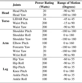
Table 1.2: Actuator specifications of THOR-OP joints
Joints Power Rating Range of Motion (Watts) (Degrees)
Head Head Pitch 20 -90 to 90
Head Yaw 20 -180 to 180
Torso LIDAR Pan 16 -45 to 45
Waist Pitch 200 -15 to 90
Waist Yaw 200 -90 to 90
Arm
Shoulder Pitch 200 -180 to 180
Shoulder Roll 200 0 to 180
Shoulder Yaw 100 -180 to 180
Elbow Pitch 100 0 to 160
Forearm Yaw 20 -180 to 180
Wrist Yaw 20 -180 to 180
Wrist Roll 20 -90 to 90
Leg
Hip Yaw 100 -60 to 55
Hip Roll 200 -90 to 35
Hip Pitch 200 -90 to 35
Knee Pitch 200 0 to 180
Ankle Pitch 200 -90 to 35
Ankle Roll 100 -90 to 35
that are designed to be used with the Dynamixel Pro actuators. They are extruded aluminum tubing
and brackets with regularly spaced bolt holes, and one can easily assemble them with hex bolts.
Figure1.4shows the structural components required for a single THOR-OP robot; the total
man-hours needed for a complete assembly from parts is estimated at 24 man-hours. With the benefit of the
modular construction of the robot, we could quickly iterate through a number of different designs.
Figure1.6shows the evolution of arm design over the course of our testing. The evolution of the
arm DOF and link lengths were completed in a short time due to the easily adaptable design.
1.2.2 Sensors and Actuators
The THOR-OP robot is decorated, Figure 1.8, with a broad range of sensors. On the head, one
Logitech C920 HD ProWebcam USB camera provides up to HD video coupled with a stereo
(a) 6 DOF arm
(b) Initial 7 DOF arm
(c) Final 7 DOF arm
Figure 1.6: Three different arm configurations evolved during development of the THOR-OP.
Logitech C905 Webcam. During testing, we evaluated an ultra wide angle USB camera to provide
additional situational awareness, but we chose not to use it as the specific unit occupied the full USB
bus and seriously affected the whole system performance.
The robot is equipped with two ethernet based Hokuyo UTM-30LX-EW LIDAR sensors, one
on the head and one in the chest. We tested outdoors and found that the LIDARs are not affected by
direct sunlight even without any special shades or covers. The chest LIDAR mounted vertically on a
yawing actuator is used to generate a local 3D representation of the surroundings for manipulation.
From our testing experience, we were confident that the 3D mesh from the chest LIDAR provided
accurate enough information for the robot to localize objects and navigate to target positions.
The head LIDAR, mounted horizontally, is mainly used to generate a 2D map using the SLAM
algorithm described in [18], however, this is not utilized since all tasks are performed in a
small-scale environment setup, where mapping is not necessary. Also, using one sensor instead of two
reduced the bandwidth usage, which was advantageous given the degraded network condition in the
DRC trials.
We used a Microstrain 3DM-GX3-45 inertial sensor located close to the center of mass of the
robot. For pose estimation, we utilized its raw accelerometer and gyro data and its extended Kalman
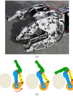
Figure 1.7: (a) The gripper for the DRC Trials consisted of two under actuated fingers to wrap around an object, and a rigid palm to give support. (b) The underactuated mechanism in the finger.
Our main design policy for the THOR-RD platform is to keep it simple and reliable, so we
keep the sensor suite nearly unchanged from the trials. A Microstrain 3DM-GX4-25 inertial sensor
provides raw accelerometer and gyro data along with filtered pose estimates. Four independent
RS485 chains provide communication to the four chains of motors via a USB interface. Two ATI
Mini58 force-torque sensors on the feet aid balancing algorithms. One Logitech C920 HD Pro USB
webcam mounted on the head captures audio and video. For more situational awareness, the left
wrist is equipped with a Logitech C905 Webcam.
For depth perception, two ethernet based Hokuyo UTM-30LX-EW LIDAR sensors are utilized.
A servo motor pans a vertically mounted LIDAR in the chest. A head mounted LIDAR provides
Figure 1.8: The overall structure of the THOR-OP hardware interconnections includes four inde-pendent motor communication buses.
2.0 sensor that provides both RGB image and colored depth readings, both in indoor and outdoor
environments. It was omitted from the Finals due to weight and power supply concerns.
The humanoid morphology is materialized with chains of position controlled servo motors.
While hydraulic actuators and high bandwidth current control occupies the minds of researchers
in robotics, the platforms in this work utilize traditional position controlled methods. One positive
properties of position controlled motors and their PID control loop, is that hierarchy in control is
preserved. No high level computation tells the exact current outputs; rather, a local micro controller
calculates these properties.
Dynamixel MX
The DARwIn-OP utilizes position controlled servo motors that communicate over a half duplex
TTL serial bus. All motors are MX-28 series3that provides stall torques of 2.5Nm and run at 12V.
The THOR-OP robot utilizes the MX-28 series for panning a LIDAR sensor and the MX-106
series4 motors for the grippers. These motors are rated for 12V; however, for manipulation, the
motors utilize 24V. This overvoltage has the potential to damage the servos but allows for more rich
and reliable gripping power.
3MX-28 series motorshttp://support.robotis.com/en/product/dynamixel/mx_series/mx-28.htm
Figure 1.9: The transparent view of the Dynamixel Pro modular actuator we use for the THOR-OP robot.
Dynamixel PRO
For most high-load joints, we use the new PRO series of Dynamixel actuators developed by Robotis,
Co. Ltd. We use three different Dynamixel Pro actuator types: H42-20-S300-R, H54-100-S500-R
and H54-200-S500-R. They are rated at 20W, 100W and 200W, respectively, and can be fitted with
a number of different reduction gear boxes.
Two different gearboxes are used, one with in-line output axle and one with parallel output axle.
Both gearboxes use cycloidal reduction gears that have a higher impact tolerance than common
harmonic drives. They utilize 4096-step absolute encoders (after gear reduction) which enables
precise control. With a maximum of 502,000 counts per revolution, the user can measure joint
angles to 0.0007 degrees allowing for high precision control. The actuators communicate over a
serial bus, where a number of actuators can be connected in a daisy chain setup. The actuators can be
commanded through position, torque and speed with electrical current sensing based control. They
are certified by the Korea Testing Laboratory and the Korea Measuring Instrumentation Research
Association to the specifications provided by the manufacturer5.
1.2.3 Power and Computation
For the on-board computation, the THOR-OP robot has two Axoimtek computers with a 1.65Ghz
dual core AMD G-series APU. Communication from these computers to the actuators goes through
a USB interface board and then is divided into four independent RS485 chains. As each of our
modular actuators has built in motor controllers and can be connected in a daisy chain network, our
control setup was simple. Due to the simplicity and efficiency of our software, our computation
load is light and we choose not to use a field computer for the competition, and instead rely on a
single on-board computer. Although this computer is not as powerful as some external computation,
it proved capable enough for our approaches. During testing, computation was concentrated in the
state machine process, which handled both the walk engine and arm planning. Total CPU utilization
was less then 40%. Memory usage was quite low, and the six processes together occupied under
10% of on-board memory.
Figure 1.10: CPU utilization of the various processes running onboard the robot. Computation fluctuated during walking phases and arm planning routines.
The robot operates on 24V for the on-board computer and actuators, except for the LIDAR
and its panning actuator, which utilizes down-converted 12V. The computer power and the actuator
power reside on a separate supply to mitigate harmful current spike effects. THOR-OP has three
LiPo battery compartments, which can power the computer, upper body and lower body in parallel
completely untethered operation, we used an external power supply for actuators and use the battery
to just power the on-board computers. Overall, the robot is fairly efficient, consuming less than
100 watts of power for most cases, with and peak power consumption never exceeding 480 watts.
Figure1.11shows the power consumption of the robot for two different locomotion scenarios.
Figure 1.11: The power consumption varies during different phases of a locomotion cycle. The top shows when THOR-OP is taking a large step over a threshold of 2.5in high, while the bottom represents walking in place. (DS: double support,LS: left support,RS: right support.)
THOR-RD’s computer and sensors run on a portable 12V 120Wh Lithium Ion battery that
pro-vides more than three hours of continuous operation in practice. Motors are powered with two
24V 488Wh Lithium Polymer batteries, which are doubled from the 288Wh batteries we used for
THOR-OP. This big battery increase ensures continuous operation for over an hour in the worst
case: in practice, the robot motor system consumes less than 250W during walking and the batteries
provide enough energy for hours of testing.
Instead of two 1.6Ghz AMD computers in THOR-OP of Trials, we use a single Core i7 Haswell
NUC computer for onboard processing. The Intel CPU provided more than twice the computation
ability with half the power consumption of the AMD computer. Due to our minimalist sensor setup
perception loads in real time. We use another NUC for the field computer that logs sensory data for
later analysis.
1.2.4 End Effectors
One of the few non-standard parts we use for the robot is the end effector. Over the course of
our preparation for the DRC, we designed and iterated multiple gripper designs. The final design
incorporates three active fingers controlled by smaller Dynamixel MX-106R actuators and a passive
palm at the opposing side, shown in Figure1.7(a). In addition, we used modular wrist attachments
with various task specific passive appendages such as rod or hook. Thus, complementing the active
gripper is a passive end effector.
Passive End Effectors
The rules of the DRC Trials specify that the robot may use multiple end-effectors to suit different
tasks as long as the robot carries all of them throughout the challenge. We used a number of
passive end-effectors for tasks that do not require finger actuation, mainly to protect the finger
mechanism from possible damage. We use three different types of appendages: straight rods for
rotating valves and steering wheels, hooks for opening and pulling the doorknob and a gear-shaped
star for tightening the hose tip. They are designed to be robust against possible misalignment, which
allows us to save time needed for fine positioning. Also, we have designed the appendages to be
mounted on the side of the wrist, so that we do not have to detach the whole hand and let the robot
carry them around.
Gripper
Each finger is an underactuated two DOF four-bar linkage that is able to conform around a wide
range of objects with secure grips [120]. To conform around objects, each finger has a passive
joint with a spring-loaded linkage mechanism [78], as shown in Figure 1.7(b). When the finger
(a) (b) (c)
Figure 1.12: The iterations of gripper design. (a) Two fingered gripper with a fixed palm. (b) Modular 3 fingered gripper. (c) Final version with a slim profile to minimize self collision.
the finger wrap around the object. In practice, our hand can securely grip a wide range of objects
including drills, hoses and wooden blocks, while being lightweight at only 797 grams.
For the DRC Finals, field operators can no longer reconfigure the gripper between tasks. A
ver-satile yet robust hand is required to handle all the given tasks while surviving contacts with objects
throughout an entire run. As it is very hard to design an actuating hand that is both lightweight and
robust against impacts, we decided to adopt an asymmetric end effector setup. We use a lightweight
active gripper in one arm and a robust passive hand in the other, and only use the active gripper when
the grasping is crucial for the completion of the task. As we cannot use task-specific appendages
any more, the active gripper needs to be more versatile. The main shortcoming of the previous
gripper is that it has only two active fingers in one side, so the palm must be very precisely aligned
with the gripping object to secure the object with full force. Also, as only one side of the hand has
actuating fingers, it is hard to pick up large objects like the wooden pieces in the Debris Task.
We designed a new three finger gripper with two main goals. It should be able to grab a wide
range of objects while tolerating some positioning error, and it should be lightweight with a short
gripping position to keep the wrist actuator load low. The iterations of the new gripper are shown
in Figure1.12. The initial design utilizes a modular finger design that uses the wrist yaw actuator
as a structural component of the assembly, with each of the modules attaching to it. The modularity
Feet
The foot is the main contact point of a humanoid robot, and its properties, such as geometry and
sole material, can greatly affect the stability of the robot. For this reason, some humanoid robotics
competitions, such as RoboCup, set limits on the foot size and the center of mass height of the robot
to keep the bipedal locomotion challenging. The DRC, on the other hand, has no such rules and it
even allows for statically stable non-humanoid robots, so there is no reason not to equip the robot
with large feet for more stability.
Figure 1.13: Foot designs suggested for the THOR-RD robot. (a) Stock THOR-OP foot (b) Proto-type foot with wide support area and internal damper. (c) Large sized foot made of carbon fiber to reduce weight. (d) Stock THOR-RD foot. (e) Adjustable foot with bolt on supports.
Still, most humanoid robots have fairly small feet, because they look more natural and they help
traversing uneven terrain with more possible footholds. Also, it requires smaller stride lengths to
step on a different surface. The original THOR-OP robot also uses a relatively small foot with thick
sole that works well for flat surface and is necessary for uneven terrain as THOR series robot has
fairly short leg dimension compared to obstacle size. However, the DRC Finals requires utmost
stability from the robot, as robots can be seriously damaged from a single fall due to the lack of
safety measures. Some teams have even decided not to walk most of the time; we have decided to
look for foot design changes that keep all the functionality of the robot while making it more stable.
We tried a number of foot design iterations, shown in Figure 1.13. We prototyped a very big
foot that almost fully covers the unit building block of the rough terrain. Such a large foot hampered
the possibility that the gas pedal area of the Polaris vehicle would pose collision issues with large
feet. The final design incorporates bolted on additional support along the foot edges. The total
width and height of foot can be adjusted easily on the field by remounting the additional supports.
Unfortunately, we found that the Polaris pedal area leaves very little room for foot size expansion,
and did not use oversized feet or bolt on supports.
1.3
Software Architecture
The software framework [92] has its roots in RoboCup international robotic soccer competition
[81]. It provides a coherent way of organizing and executing processes for motion planning, sensor
processing, autonomy and communication interfaces. It is designed to be highly modular to support
a variety of robotic hardware and be quickly ported on new humanoid platforms with minimal
ef-fort. Outside of RoboCup soccer, humanoids perform manipulation tasks and interact with humans.
These tasks are immeasurably important. In the RoboCup @Home league, for instance, robots must
manipulate objects on tables, as well as interpret commands from a human. In RoboCupRescue puts
an emphasis on exploration using sensors not allowed in the soccer competitions. However, the
re-cent DARPA Robotics competition has actually merged RoboCup soccer and the Rescue league by
encouraging humanoid robots to be used in disaster relief scenarios. Many people involved in the
RoboCup effort are working on this DARPA project, and so the software must scale to achieve this
broader impact.
The framework has been tested with different humanoid robots including the Nao [38], DARwIn
series [98] and CHARLI [44]. Due to the extensible nature of the framework, writing only a new
interface module and kinematic description suffice to port the code to new humanoid robots. Various
physical platforms are shown in Figure1.14; for instance the simulated open source ATLAS model
can perform manipulation. The open source release can be obtained online6.
The simple build system and test scripts utilize C/C++ as little as possible, in favor of using
Lua where it makes sense. Providing more operation modes that the DARPA challenge and other
6UPennalizers source code
Figure 1.14: The flexible software leads to various supported humanoid robotic platforms. Top, from left: THOR-RD, DARwIn-OP, Aldebaran Nao. Bottom, from left: Simulated ATLAS, DARwIn-HP, Mini-HUBO, DARwIn-LC.
RoboCup leagues require means that more information, like transformation matrices, need to be
shared. By combining the message passing methods of ZeroMQ7 with shared memory segments,
we are able to achieve these goals, but it is an active area of research to ensure robustness of data
and as little latency as possible. Figure1.16depicts how processes are segmented by role and the
way they interact with shared memory and the network channels.
The software is written in a combination of Lua8, Torch7 tensor manipulation library [27],
C/C++, MATLAB9and JavaScript. The Lua portions operate the high level State Machine, Vision
and Locomotion processes. The C/C++ routines implement the low level processing, handling
interactions to motors and sensor systems along with the kinematics engine. The MATLAB portion
provides debugging and the JavaScript presents a flexible user interface. This platform is small
and efficient framework with just over 15,000 lines of code to support all platforms, including a
simulator.
From designing and gathering components to building and tuning algorithms, humanoid
soft-7ZeroMQ: The Guide.http://zguide.zeromq.org/ 8The Programming Language Luahttp://www.lua.org
Figure 1.15: Block Diagram of the Software Architecture.
ware development can be a cumbersome process. To reduce overhead in applying algorithms and
testing across several humanoid platforms, a modularized software platform provides interfaces the
many components that are common among humanoids. The modularized platform separates low
level components that vary from robot to robot from the high level logic that does not vary across
robots. The low level components include processes to communicate with motors and sensors on the
robot, while supporting simulation packages. The high level components include the state machines
that control how the humanoids move around and process sensor data.
1.3.1 Hierarchical Behaviors
At the lowest level, there are a number of raw I/O processes, which includes the motor control
processes that keeps publishing to four chains of the Dynamixel actuators at 120 Hz, the IMU
process that reads accelerometer, gyro, and filtered orientation data at 100 Hz, the camera processes
that updates camera frame grabs from head and wrist cameras at 15 Hz and 5 Hz, the auditory
process that monitors the microphone signal levels. They typically uses shared memory interface as
the new data are streamed in roughly fixed rate.
Per-Figure 1.16: The software architecture centers around shared memory
ception processes accumulate the sensory data, build a 3D mesh and detect features, before sending
the results to the remote operator. Lower and upper body motion controllers receive high level
commands and generate motions for the lower or upper body, such as locomotion or manipulation
motions.
Finally, a number of finite state machines (FSMs) govern the high level behavior of the robot. An
overarchingBodyFSMcontrols the underlyingMotionFSM,ArmFSM, andHeadFSMmodules. Each
state machine is updated at 120Hz to match the motor update rate. The MotionFSMhandles the
locomotion and balancing of the robot, theArmFSMruns the upper body control, and theHeadFSM
controls head motions. TheBodyFSMtransition between waypoint following, standing and driving
modes by sending signals to the other state machines. Once in a standing mode, theArmFSMcontrols
arm states, such as valve pre-positioning, tucking arms, and entering teleoperation. Transitions are
commanded remotely and forwarding via the remote procedure call system.
Low Level Management
The low level communication with the actuators and sensors is split into a completely separate
pro-cess from the high level behavioral logic. This separation ensures that the low level communication
is continuously operated at the highest rate possible, regardless of the rest of the system.
communication of the robot, possibly resulting in jerky or unstable movement of the robot. The
communication process constantly writes all servomotors’ desired angles and reads the
servomo-tors’ current joint encoder measurements; it also polls onboard sensors such as inertial sensors or
buttons.
The platform-specific motors and sensors process manager interacts with the NaoQi10 module
and, for the more general DARwIn platform, interacts directly with the Dynamixel servomotors
and onboard sensors using the Dynamixel protocol11. Linux shared memory managed motor and
sensor data for use across processes. Two shared memory blocks store motor data and sensory data.
The motor block includes motor command variables such as target position, electrical compliance,
maximum velocity, and other related variables. The sensory block shares readings such as joint
encoder values, as well as accelerometer and gyroscope measurements. By using shared memory,
other processes, like MATLAB, can provide debugging tools.
Simulation
The Webots [95], [153] simulation platform aids in evaluating the software behaviors. Using a
simulator allows for rapid prototyping, with reasonable speeds, even for full physics simulation.
Shown in Figure1.17is an example of two teams of four robots running our code. Each team (or
even each player) can be slightly modified to run a different parameter set. The software is tested
on Mac and Linux operating systems. Support for the Gazebo simulation platform [72] allows a
diversity of simulation platform..
The software platform is extensively tested in competition each year during RoboCup. The
physical model in simulation helps to identify torque limits for motions and validate dynamic
mo-tions before attempting on the physical robot. The simulated physics updates at 8ms, while the
simulated sensors update at the same rates as the physical robot. The operator systems interact with
the simulator or real robot with minor configuration tweaks.
10Aldebaran Nao documentationhttp://doc.aldebaran.com
11Dynamixel protocol specification http://support.robotis.com/en/product/dynamixel/dxl/
Figure 1.17: Teamplay is simulated using Webots to rapidly prototype behaviors that perform simi-larly on real hardware.
Kinematics and Keyframes
The locomotion code uses forward and inverse kinematics solvers that platform specific to account
for the differences in humanoid limb configurations. Due to the possible hardware constraint such
as the hip joint of the Nao robot, platform specific kinematics solvers must be used. Figure1.18
provides an example of two humanoid kinematics configurations.
Using the platform specific kinematics solvers, a system retrieves motor mapping from
anatomi-cal descriptions of the humanoid to joint ids. This allows functions to be named aptly asget head position,
etc. In addition to commanding limb end effectors to certain positions, prerecorded keyframe
mo-tions can be played back. The keyframe motion is typically used for kicking and standing up
behav-iors. Keyframe data is platform specific as well, which is automatically selected for each platform
Figure 1.18: The kinematics of the Nao [38] and DARwIn-OP share a humanoid morphology.
Locomotion
In the framework, the zero moment point (ZMP) [149] based omnidirectional dynamic walking
controller governs humanoid locomotion. An analytic ZMP trajectory is generated in real time
ac-cording to the commanded walk velocity from the Behavioral logic. The center of mass (COM)
tra-jectory is also calculated in real time to meet the ZMP criteria. A combination of the
optimization-based approach such as ZMP preview method [63], [136] and the analytic solution of a piecewise
linear ZMP target is employed for specialized locomotion methods [164]. This combination
pro-vides the best of both worlds for reactive walking with application specific motions. After the foot
and COM trajectory is calculated, the inverse kinematics solver generates joint angle values for the
leg actuators. Shown in Figure1.19is a detailed look at how commanded walking velocities are
transformed into joint commands.
The walking controller also includes stabilization control using sensory feedback to reject
exter-nal disturbances and surface irregularities. Two sources provide sensory feedback - proprioception
and inertial measurements. For proprioception, joint encoder angles from leg actuators and the
rel-ative angle between support leg frame and torso frame are fed to the forward kinematics solver. For
inertial feedback, the current angular velocity of the torso are measured using the torso-mounted