University of Pennsylvania
ScholarlyCommons
Publicly Accessible Penn Dissertations
1-1-2013
Imaging and Understanding Atomic-Scale
Adhesion and Wear: Quantitative investigations
Using in situ TEM
Tevis Jacobs
University of Pennsylvania, [email protected]
Follow this and additional works at:http://repository.upenn.edu/edissertations
Part of theMechanical Engineering Commons, and theMechanics of Materials Commons
This paper is posted at ScholarlyCommons.http://repository.upenn.edu/edissertations/766 Recommended Citation
Jacobs, Tevis, "Imaging and Understanding Atomic-Scale Adhesion and Wear: Quantitative investigations Using in situ TEM" (2013). Publicly Accessible Penn Dissertations. 766.
Imaging and Understanding Atomic-Scale Adhesion and Wear:
Quantitative investigations Using in situ TEM
Abstract
The underlying physics governing tribological interactions - adhesion, friction, lubrication, and wear - are poorly understood. Significant progress has been enabled by nanoscale studies using the atomic force microscope (AFM). However, AFM lacks direct access to the contact geometry and structure. In this thesis, nanoscale adhesion and wear tests were performed inside of a transmission electron microscope (TEM), enabling real-time in situ interrogation of the contact in vacuum. Quantitative data was extracted using custom analysis routines to resolve tip shape, volume changes, and adhesive forces with unprecedented resolution.
From in situ adhesion tests, a novel method was developed to extract the work of adhesion (0.66±0.14 J/ m^2) and range of adhesion (0.25±0.06 nm) between silicon and diamond. The latter quantity has not previously been measured experimentally. TEM adhesion tests and complementary atomistic simulations reveal an order-of-magnitude reduction in apparent work of adhesion as tip roughness increased from atomic-scale to a root-mean-square value of 1 nm. Using an existing analytical model, an empirically derived
roughness-independent adhesion parameter was extracted. In situ wear tests of silicon on diamond at low load revealed the mechanism of wear to be consistent with atom-by-atom processes. The rate of atomic removal varied exponentially with average normal stress, consistent with stress-mediated chemical reaction kinetics. This yields a physically reasonable activation energy (0.85±0.06 eV), and activation volume (6.7±0.3 �). This framework can be generalized to understand and potentially predict wear in many materials undergoing atom-by-atom removal.
Together, these investigations advance the scientific understanding of nanoscale adhesion and wear and help bridge the gap between experiments and atomistic simulations. Three examples are demonstrated where nanometer-scale trends can be predicted using continuum approaches: nanoscale adhesive forces can be calculated using an interaction potential; apparent work of adhesion depends on nanoscale root-mean-square roughness; and the rate of atomic-scale wear reactions is determined by the average normal contact stress. These examples, while only demonstrated in the specific systems studied, suggest strategies and future research directions for understanding, predicting, and controlling tribological phenomena.
Degree Type
Dissertation
Degree Name
Doctor of Philosophy (PhD)
Graduate Group
Materials Science & Engineering
First Advisor
Keywords
Adhesion, AFM, Nanoscale, Roughness, TEM, Wear
Subject Categories
IMAGING AND UNDERSTANDING ATOMIC-SCALE ADHESION AND WEAR:
QUANTITATIVE INVESTIGATIONS USING IN SITU TEM
Tevis David Bartow Jacobs
A DISSERTATION
in
Materials Science and Engineering
Presented to the Faculties of the University of Pennsylvania
in
Partial Fulfillment of the Requirements for the
Degree of Doctor of Philosophy
2013
Supervisor of Dissertation
Signature
Robert W. Carpick, Professor and Chair, Mechanical Engineering & Applied Mechanics
Graduate Group Chairperson
Signature
Russell J. Composto, Professor, Materials Science & Engineering
Dissertation Committee
Daniel S. Gianola, Assistant Professor, Materials Science & Engineering
John L. Bassani, Richard H. and S.L. Gabel Professor, Mechanical Engineering & Applied Mechanics
Ju Li, Battelle Energy Alliance Professor of Nuclear Science and Engineering
IMAGING AND UNDERSTANDING ATOMIC-SCALE ADHESION AND WEAR:
QUANTITATIVE INVESTIGATIONS USING IN SITU TEM
COPYRIGHT 2013
ACKNOWLEDGMENTS
First and foremost, I wish to thank my advisor, a source of inspiration and
guidance throughout the process.
I want to thank Prof. Dan Gianola, Prof. John Bassani, and Prof. Ju Li for serving
on my PhD committee and providing scientific guidance and support along the way.
I have far too many other people to thank. I could not have completed this
without help from countless people. Here is a short (and partial) list of the many people
who have helped me throughout my PhD.
I am grateful for helpful discussions and collaborations with Prof. Kevin Turner.
Also, many thanks to Dr. Dave Grierson for scientific discussions and programming
assistance. Dr. Doug Yates, Dr. Lolita Rotkina, Dr. Jamie Ford, and Dr. Ryan Major
provided a great deal of microscopy and equipment assistance.
Direct scientific and technical assistance with this work was provided by Joel
Lefever, Alex Goodman, and Sarah Badin. Graham E. Wabiszewski performed AFM on
the indenter tip (Chapter 3) and provided much other technical help. I wish to thank
Peter Rockett for help with design, and also manufacturing of the fixture described in
Chapter 3.
I wish to thank my qualifying committee, Prof. Vaclav Vitek, Prof. Mahadevan
Khantha, Prof. Charles McMahan, and Prof. I-Wei Chen, for challenging me and spurring
the creation of the analysis in Chapter 6.
I have been fortunate to have excellent collaborators at various institutions: at the
Marcel Fallet; at National Chung Cheng University (Taiwan): Prof. Yeau-Ren Jeng, Dr.
Kent Wu; at the Center for Integrated Nanotechnology (Sandia): Dr. Jianyu Hwang, Dr.
Jiangwei Wang, Dr. Yang Liu; and at Advanced Diamond Technologies, Inc: Dr.
Nicolaie Moldovan, Dr. Hongjun Zeng, and Dr. John Carlisle.
I wish to thank Pat Overend, Vicky Lee, Irene Clements, Maryeileen Griffith, Sue
Waddington-Pilder, Olivia Brubaker, and Desirae Johnson for support and much
logistical help.
I wish to thank the current, former (and honorary) members of the Carpick
Research Group for support, assistance, guidance, and much fun.
Use of the facilities of the Pennsylvania Regional Nanotechnology Facility is
acknowledged. Also, funding from the National Science Foundation (Grants
ABSTRACT'
IMAGING AND UNDERSTANDING ATOMIC-SCALE ADHESION AND WEAR:
QUANTITATIVE INVESTIGATIONS USING IN SITU TEM
Tevis D. B. Jacobs
Robert W. Carpick
The underlying physics governing tribological interactions – adhesion, friction,
lubrication, and wear - are poorly understood. Significant progress has been enabled by
nanoscale studies using the atomic force microscope (AFM). However, AFM lacks direct
access to the contact geometry and structure. In this thesis, nanoscale adhesion and wear
tests were performed inside of a transmission electron microscope (TEM), enabling
real-time in situ interrogation of the contact in vacuum. Quantitative data was extracted using
custom analysis routines to resolve tip shape, volume changes, and adhesive forces with
unprecedented resolution.
From in situ adhesion tests, a novel method was developed to extract the work of
adhesion (0.66±0.14 J/m2) and range of adhesion (0.25±0.06 nm) between silicon and
diamond. The latter quantity has not previously been measured experimentally. TEM
adhesion tests and complementary atomistic simulations reveal an order-of-magnitude
reduction in apparent work of adhesion as tip roughness increased from atomic-scale to a
root-mean-square value of 1 nm. Using an existing analytical model, an empirically
derived roughness-independent adhesion parameter was extracted. In situ wear tests of
silicon on diamond at low load revealed the mechanism of wear to be consistent with
normal stress, consistent with stress-mediated chemical reaction kinetics. This yields a
physically reasonable activation energy (0.85±0.06 eV), and activation volume
(6.7±0.3 Å). This framework can be generalized to understand and potentially predict
wear in many materials undergoing atom-by-atom removal.
Together, these investigations advance the scientific understanding of nanoscale
adhesion and wear and help bridge the gap between experiments and atomistic
simulations. Three examples are demonstrated where nanometer-scale trends can be
predicted using continuum approaches: nanoscale adhesive forces can be calculated using
an interaction potential; apparent work of adhesion depends on nanoscale
root-mean-square roughness; and the rate of atomic-scale wear reactions is determined by the
average normal contact stress. These examples, while only demonstrated in the specific
systems studied, suggest strategies and future research directions for understanding,
TABLE OF CONTENTS
ABSTRACT'...'VI!
LIST'OF'TABLES'...'XII!
LIST'OF'FIGURES'...'XIII!
LIST'OF'SYMBOLS'...'XVI!
Latin&Characters!...!xvi!
Greek&Characters!...!xvii!
LIST'OF'ACRONYMS'...'XVIII! CHAPTER'1:'THE'IMPORTANCE'OF'NANOTRIBOLOGY'...'1!
101:! Motivation&for&the&study&of&nanotribology!...!2!
102:! Motivation&for&in!situ!investigations&into&tribology&at&the&nanoscale!...!5!
103:! Structure&of&the&present&thesis!...!7!
104:! References!...!9!
CHAPTER'2:'ADHESION'AND'WEAR'AT'THE'NANOSCALE'–'A'REVIEW'...'11!
201:! Structure&of&the&present&chapter!...!11!
202:! Relevant&results&from&continuum&contact&mechanics!...!12!
20201:! The&importance&of&continuum&results&in&a&discussion&of&nanoscale&contacts!...!12!
20202:! Relevant&results&from&sphere0on0sphere&continuum&contact&mechanics!...!15!
20203:! Modeling&adhesion&for&non0spherical&geometries!...!21!
20204:! The&generality&of&measurements&of&work&of&adhesion&and&range&of&adhesion,&and&the&difficulty& of&their&measurement!...!24!
20205:! Concluding&remarks&about&continuum&contact&mechanics&and&the&use&of&adhesion&potentials!25! 203:! Relevant&prior&work&on&adhesion&as&a&function&of&roughness!...!26!
20301:! Relevant&models&of&roughness&and&adhesion&based&on&contact&mechanics&or&van&der&Waals& adhesion&!...!27!
204:! A&review&of&nanoscale&wear&tests&performed&using&the&atomic&forceµscope&and&their&
comparison&to¯o0scale&wear!...!33!
20401:! A&brief&review&of&relevant&results&from&wear&at¯oscopic&length&scales!...!33!
20402:! Nanoscale&wear&tests&using&the&atomic&forceµscope&and&deviations&from&the&Archard& equation&!...!35!
20403:! Nanoscale&wear&laws&based&conceptually&on&reaction&rate&theory!...!37!
20404:! Concluding&remarks&about&AFM0based&nanoscale&wear&tests!...!45!
205:! Investigations&into&nanoscale&wear&using&ex!situ!and!in!situ!imaging;&demonstrated&nanoscale&wear& mechanisms!...!45!
20501:! Imaging&a&wearing&probe&using&ex!situ!electronµscopy!...!45!
20502:! Fully&in!situ&investigations&into&nanoscale&wear!...!50!
20503:! Concluding&remarks&about&ex!situ&and&fully&in!situ&nanoscale&wear&tests!...!52!
206:! References!...!54!
CHAPTER'3:'METHODOLOGY'–'USING'TEM'TO'INVESTIGATE'NANOSCALE' CONTACT'PHENOMENA'...'58!
301:! Examining&AFM&tips&in&the&TEM&(for!ex!situ!testing)!...!58!
30101:&Limitations&of&previous&fixture&designs&for&imaging&of&AFM&probes&using&TEM!...!59!
30102:&Description&of&the&novel&fixture&design&for&imaging&of&AFM&probes&using&TEM!...!61!
30103:&An&improvement&in&mounting&reproducibility&enabled&by&the&novel&fixture!...!62!
30104:&Examples&of&use&of&the&novel&fixture,&and&suggested&applications&beyond&the&present& investigation.!...!63!
302:&! Apparatus&and&calibration&for&in!situ&adhesion&and&wear&tests&inside&the&TEM!...!64!
30201:! Instrumentation!...!64!
30202:! Modification&for&increasing&the&resolution&of&contact&force&measurement!...!66!
30203:! Calibration&of&the&indenter&motion&and&the&cantilever&spring&constant&prior&to&testing!...!67!
303:&! Test&methodology&for&in!situ&adhesion&and&wear&tests&inside&the&TEM!...!68!
30301:! Mounting&of&AFM&chips&for&testing!...!68!
30302:! Materials&selection&and&surface&preparation&for&adhesion&and&wear&testing!...!71!
30303:! Methodology&for&in!situ!adhesion&testing!...!73!
30304:! Methodology&for&in!situ!wear&testing!...!75!
304:&! Data&processing:&Analyzing&and&quantifying&the&images&and&video!...!76!
30401:! Direct&observation&of&tip&shape&and&modification&in&the&TEM&images&and&video!...!76!
30402:! Algorithms&for&extracting&the&outer&profile&of&the&AFM&tips!...!77!
30403:! Algorithms&for&fitting&the&overall&tip&shape,&and&computing&its&surface&roughness!...!79!
30404:! Algorithm&for&extracting&the&snap0in&distance&and&pull0off&force&from&videos&of&tests!...!80!
30405:! Algorithms&for&integrating&the&interaction&potential&and&computing&relevant&quantities!...!81!
30406:! Algorithms&for&aligning&pre0/post0wear&contours&and&calculating&volume&lost!...!83!
305:&! References!...!86!
4"1:! Using*an*interaction*potential*to*calculate*expected*adhesion*values*for*model*shapes!...!88!
4"1"1:! Calculating*tip"sample*force"separation*curves*using*probes*with*standardized*shapes:*the* forward*calculation!...!89!
4"1"2:! Restricting*the*minimum*tip"sample*separation*distance*to*the*value*of*the*adhesive*range!.!93! 4"1"3:! Calculating*adhesion*parameters*for*the*same*standardized*shapes:*the*reverse*calculation!.!96! 4"2:! Measuring*adhesive*interaction*parameters*in*real*materials!...!98!
4"2"1:! Modification*of*the*technique*to*account*for*vibration!...!99!
4"2"2:! Measurement*of*adhesion*parameters*for*a*silicon*tip*on*a*diamond*surface!...!100!
4"3:! Assessing*the*reliability*of*the*measured*parameters!...!102!
4"3"1:! Comparing*the*range*of*adhesion*with*previously*proposed*values!...!103!
4"3"2:! Comparing*the*work*of*adhesion*with*previously*proposed*values!...!105!
4"3"3:! Origins*of*the*large*amounts*of*scatter*in*the*data!...!110!
4"3"4:! Impact*of*the*present*technique*for*adhesion*characterization!...!111!
4"4:! Conclusions*regarding*the*measurement*of*adhesion*parameters!...!112!
4"5:! References!...!113!
CHAPTER(5:(NANOSCALE(ADHESION,(PART(II:(THE(EFFECT(OF(ATOMIC4SCALE( ROUGHNESS(...(115!
5"1:! Analytical*results:*A*simple*numerical*model*of*roughness!...!116!
5"2:! Measuring*adhesion*with*direct,*concurrent*measurements*of*tip*topography!...!120!
5"2"1:! Experimental*in!situ*TEM*measurements!...!120!
5"2"2:! Complementary*simulated*adhesion*tests*performed*by*collaborators!...!124!
5"2"3:! Fitting*experimental*and*simulation*results*with*a*simple*literature*model!...!130!
5"3:! Suggestion*of*a*roughness"independent*adhesion*parameter!...!133!
5"4:! Conclusions!...!135!
5"5:! References!...!137!
CHAPTER(6:(NANOSCALE(WEAR,(PART(I:(THE(APPLICATION(OF(REACTION( RATE(THEORY(TO(NANOSCALE(WEAR(...(138!
6"1:! Review*of*reaction*rate*theory!...!138!
6"1"1:! Case*study*on*reaction*rate*theory:*Plastic*flow*by*dislocation*glide!...!142!
6"2:! Formalizing*the*application*of*reaction*rate*theory*to*wear!...!147!
6"2"1:! Expanding*on*the*model*of*atomic"scale*wear*as*a*thermally*activated*process!...!149!
6"2"2:! The*extraction*of*activation*parameters*for*wear!...!153!
6"2"3:! The*interpretation*of*activation*parameters!...!158!
60301:! Experimentally&demonstrating&wear&mechanisms&and&wear&kinetics&in&high&resolution!...!160!
60302:! Experimentally&demonstrating&the&effect&of&temperature&on&atomic0scale&wear!...!161!
60303:! Determining&which&is&the&primary&“activating&stress”&for&atomic0scale&wear!...!162!
60304:! Disentangling&the&effect&of&velocity&on&atomic0scale&wear!...!163!
60305:! Using&atomistic&simulations&to&elucidate&atomic0scale&wear!...!165!
604:! Conclusions!...!167!
605:! References!...!169!
CHAPTER'7:'NANOSCALE'WEAR,'PART'II:'EXPERIMENTALLY'DEMONSTRATING' WEAR'OF'SILICON'AS'A'STRESSAASSISTED'CHEMICAL'REACTION'...'172!
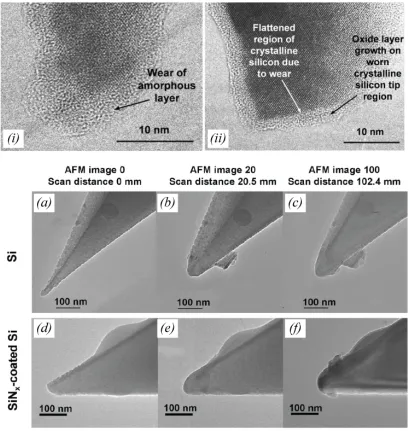
701:! Observing&and&distinguishing&wear&mechanisms&in&silicon&and&its&oxide!...!172!
702:! Quantifying&the&rate&of&wear&of&silicon&and&testing&predictions&based&on&reaction&rate&theory!...!180!
70201:! Calculation&of&mean&normal&stress!...!183!
70202:! Calculation&of&the&reaction&rate!...!187!
70203:! Results&and&discussion&of&reaction&rate&as&a&function&of&normal&stress!...!189!
703:! Quantifying&the&rate&of&wear&of&silicon&oxide!...!191!
704:! Conclusions!...!193!
705:! References!...!194!
CHAPTER'8:'CONCLUSIONS'AND'FUTURE'WORK'...'195!
801:! Summary&of&results&from&nanoscale&adhesion&and&wear,&and&broader&impacts&on&those&fields!...!195!
80101:! The&measurement&of&fundamental¶meters&governing&adhesion!...!195!
80102:! Concluding&remarks&on&nanoscale&wear!...!198!
802:! Emergent&conclusions&from&the&work&as&a&whole:&Capturing&the&effect&of&atomic0scale&detail!...!199!
803:! Open&questions&and&suggested&future&work!...!202!
80301:&! Open&questions&from&the&present&investigation!...!202!
80302:! Suggested&future&work!...!204!
804:! References!...!207!
!
LIST'OF'TABLES''
Table 4.1: Measured and calculated values for the three probes used in adhesion testing (probes are shown in Fig. 4.4)...101
Table 4.2: Values of z0 that have been proposed in previously published investigations...104
Table 4.3: Values of Wadh that have been measured in previously published experimental
investigations of relevant contact pairs...106
Table 4.4: Values of Wadh that have been measured in previously published simulation
investigations of relevant contact pairs...107
Table 5.1: All data from the experimental and simulated adhesion tests...124
LIST'OF'FIGURES''
Figure 2.1: Pressure distributions in nanoscale contacts obey predictions of continuum contact mechanics in some cases, and deviate significantly in others; the difference appears to arise due to atomic-scale surface detail...13
Figure 2.2: The Hertz model describes non-adhesive contact between two spheres using
continuum contact mechanics...17
Figure 2.3: Continuum mechanics models have been developed to describe contact in the
presence of adhesion...19
Figure 2.4: An interaction potential defines the adhesive force between two bodies as a function of separation distance...22
Figure 2.5: Roughness has been experimentally demonstrated to dramatically reduce adhesion; various analytical equations have been proposed for a wide variety of model systems...28
Figure 2.6: Nanoscale wear tests performed in the AFM demonstrate varying wear rates with sliding distance, in contrast to the macroscale Archard equation...37
Figure 2.7: Several AFM-based investigations into nanoscale wear of surfaces and tips have been analyzed assuming an exponential dependence of wear rate on load or stress in the contact...40
Figure 2.8: Using ex situ TEM imaging at intervals during an AFM-based wear test allows visualization of the tip geometry and provides some evidence of wear mechanisms...47
Figure 2.9: Periodic ex situ TEM images have been used to calculate the amount of volume lost from the wearing tips; removed quantities as small as 105 nm3 have been observed...49
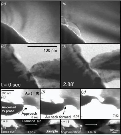
Figure 2.10: Several fully in situ wear studies have directly visualized wear processes in real time...51
Figure 3.2: The novel fixture allows imaging of AFM probes with reproducible orientations...64
Figure 3.3: A modified in situ indentation apparatus is used for adhesion and sliding tests...67
Figure 3.4: Algorithms were created to trace the contours of the probe and compare traces taken at various points throughout a wear test. ...78
Figure 3.5: Lattice-resolved out-of-contact images of the tip were used to calculate the
instantaneous volume lost at various points throughout the wear test...84
Figure 4.1: Force-separation curves were calculated for standardized shapes to establish trends of behavior and to allow for comparison with previously published results...91
Figure 4.2: A minor modification to the model must be made to prevent extremely sharp tip apexes from developing unphysically high stresses...95
Figure 4.3: The approach is demonstrated for calculation of work of adhesion Wadh and range of
adhesion z0 based on quantities measured using in situ adhesion tests. ...97
Figure 5.1: By applying a Lennard-Jones surface potential to a model tip composed of a sinusoid superimposed on a paraboloid, the essential trends of adhesion as a function of roughness are demonstrated. ...118
Figure 5.2: In situ adhesion tests were used to measure adhesive forces on asperities of diamond-like carbon and ultrananocrystalline diamond against a single crystal diamond substrate...121
Figure 5.3: The roughness of each tested tip has been characterized with sub-nanometer
resolution...123
Figure 5.4: Simulated adhesion tests were performed by collaborators using molecular dynamics, conditions were matched as closely as possible to the TEM adhesion tests...126
Figure 5.6: The experimental and simulated tests show a consistent trend of adhesion with
roughness; this trend is well-fit using a previously proposed roughness model...129
Figure 6.1: Reaction rate theory describes the kinetics of thermally activated processes...140
Figure 6.2: Reaction rate theory was successfully applied to plasticity and the movement of dislocations under stress; this earlier case study provides insights into the present application to nanoscale wear...144
Figure 6.3: A potential reaction pathway for nanoscale wear has been proposed in which the rate-limiting reaction is the initial formation of a chemical bond across the interface...151
Figure 7.1: In situ sliding wear tests were performed on four silicon tips of varying geometries. ...174
Figure 7.2: Overlaid traces show that silicon wear is gradual...176
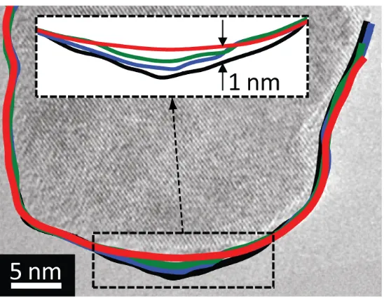
Figure 7.3: After three sliding intervals, each of 200 nm, the recession of the surface of the tip is approximately 1 nm, and the underlying lattice is undamaged...178
Figure 7.4: The volume of silicon lost due to wear has been quantified and is well described using a chemical kinetics framework...182
Figure 7.5: Parabolic profiles were fit to the near-tip geometry of the probe at every stage in the wear test...186
Figure 7.6: The wear data for silicon oxide can also be analyzed for those intervals where it appeared to be gradual...192
LIST'OF'SYMBOLS'
Latin&Characters&
A amplitude of sine wave for artificial roughness
Acontact contact area
A1:2 Hamaker constant between materials 1 and 2
acontact contact radius
b Burger’s vector
c constant term
C, D empirical constants used in the Lennard-Jones interatomic potential
D0 minimum separation or cut-off distance of the van der Waals potential
dslide sliding distance
E* effective modulus of two materials in contact
E1, E2 elastic modulus of two materials in contact
Einteraction interaction energy between two atoms
f frequency
F force (type indicated by subscript: Fadhesive, Fapplied, etc.)
H hardness of material
h height of AFM tip
hP Planck’s constant
KArchard dimensionless wear coefficient
kArchard dimensional wear coefficient
k rate of reaction
kB Boltzmann constant
l lattice constant of a crystalline material
N number (atoms, defects, etc.)
n power exponent in a power-law shape
r cylindrical polar coordinate, radial dimension
R2 regression coefficient
R1, R2, Rtip radius of the body indicated by the subscript
Ra average surface roughness
Reff effective radius of two bodies in contact
Rq root-mean-square surface roughness
T temperature
tslide time in sliding contact
v sliding velocity
vtrack velocity of growth of the wear track
Vlost volume removed due to wear
Wadh work of adhesion between two surfaces
z cylindrical polar coordinate, height dimension
z0 the equilibrium separation distance between two flat surfaces in contact
&
Greek&Characters&
Δ measured cantilever deflection
ΔAact activation area
ΔFact Helmholtz free energy of activation
ΔGact Gibbs free energy of activation on
ΔSact activation entropy
ΔUact activation energy
ΔVact activation volume
ΔWact work done during transition from initial state to activated state
δ contact deformation
ε strain
θ angle
λ wavelength of sine wave for artificial roughness
µT Tabor parameter
τ shear stress
ν1, ν2 Poisson ratio of two materials in contact
ξ pressure dependence of shear stress
ρ, ρsurf number density of atoms in a volume, surface, respectively
LIST'OF'ACRONYMS'
AFM atomic force microscopy
DLC diamond-like carbon
DMT Derjaguin-Müller-Toporov contact model
FIB focused ion beam
GNP gross national product
JKR Johnson-Kendall-Roberts contact model
MD molecular dynamics
MEMS microelectronic mechanical systems
NEMS nanoelectronic mechanical systems
RMS root mean square
SEM scanning electron microscopy
TEM transmission electron microscopy
UNCD ultrananocrystalline diamond
CHAPTER'1:'The'importance'of'nanotribology'
Tribology is the study of sliding surfaces and related phenomena including
friction, adhesion, lubrication, and wear. The study of tribology draws insights from a
broad range of disciplines, from physics and chemistry to materials science and
mechanical engineering. The lessons learned apply equally broadly: to other scientific
fields, such as geology and biology, and to industries from manufacturing and
transportation to medical devices and food processing technology. The study of
tribological topics can be traced back at least 500 years, with diagrams in Leonardo da
Vinci’s notebooks (1). The use of tribological concepts dates back much further; wall
paintings show ancient Egyptians using greased or rolling contacts to move heavy objects
almost 4000 years ago (2). Evolution has been “using” these concepts even longer – 85
million year-old fossils of the hadrosaurid dinosaur show evidence that differentially
wearing dental structures created self-sharpening teeth (3).
The field of tribology was named and its importance fully recognized after a 1966
United Kingdom government report (described in Ref. (4)) estimated that a sum of
money equal to 4% of gross national product was wasted annually due to friction and
wear, and one fourth of that sum could be recovered through greater attention to
tribology: friction, adhesion, lubrication and wear. Subsequently, more comprehensive
studies have shown it to be true across many countries and have increased the
recoverable estimate to roughly 1.5% of GNP (5) or more than 100 billion dollars
annually in the US alone. These reports motivated significant research activity, and entire
are devoted to research in the field. Enormous progress has been made in the
measurement and control of systems with sliding interfaces; an example success story is
the automobile industry, where improvements in material selection, component design,
and engine operating conditions resulted in a 25% increase in average fuel economy
between 1980 and 2005, despite an almost 100% increase in average horsepower over the
same period (6).
101:& Motivation&for&the&study&of&nanotribology&
Much of the aforementioned progress, however, has been enabled through
trial-and-error, empiricism, and the creation and use of phenomenological laws. The
interaction of two bodies making contact and/or sliding will be governed by the complex
interaction of a large number of physical parameters: the composition, material
properties, and bulk shape of the two bodies forming the contact; the topography,
chemistry, crystallinity and even identity (if oxidized, contaminated, or passivated) of the
surfaces of those bodies; the sliding conditions (speed, normal load, direction); and the
environment (air, vacuum, lubricant). Further, the interface is evolving dynamically, as
bonds can form across the interface, deformation and wear can change the geometry of
the bodies, and material removal or the formation of “tribo-layers” can even change the
identity of the materials in contact. While significant advances in models and
experiments were made during the 1930s and 1940s by Bowden and Tabor (7) (for
instance, the realization that friction can be modeled as scaling with the true area of
models in tribology. To this day, there are no models that can predict friction coefficients
or wear rates from first principles (8) – despite considerable economic motivation and
scientific effort.
One promising path to create fundamental models for tribology is to study contact
at the nanometer-scale. It has long been known that nearly all real macroscopic surfaces
are rough, and so the contact of two apparently flat bodies occurs at only a relatively
small number of local high points, or asperities. To further complicate the contact,
roughness occurs over many length scales, with “protuberances on protuberances on
protuberances” (9) or fractal-like structures; thus, the actual geometries of contact may be
orders of magnitude smaller than the apparent dimensions of the bodies. This fractal-like
behavior is limited in the small wavelength by the discrete nature of atoms. Therefore,
the fundamental behavior of even micro- and macro-scale contacts is typically governed
by nanoscale asperity contacts, and by atomic-scale processes that occur at these contact
points.
Recent scientific and industrial progress at the nanoscale has enabled direct
experimental studies of nanoscale single asperities. Most significantly for tribology is the
development, proliferation, and diversification of atomic force microscopy – which
measures the interaction between a sharp nanoscale asperity and nearly any surface of
interest. The atomic force microscope (AFM) can easily measure forces with piconewton
resolutions and can resolve topography on the picometer scale (10) – in some modes
resolving the atomic lattice (11) or even single molecules (12). Further, it can be
performed with precisely controlled sliding velocity, well-characterized surfaces, and
enabled unprecedented resolution of and control over all of the many variables associated
with a sliding contact. This allowed the careful variation of a small number of variables
to determine their action, and has facilitated numerous breakthrough investigations in
single-asperity friction, adhesion, and wear (as reviewed, for example, in Ref. (13)).
Examples of scientific breakthroughs enabled by the AFM include (among many
others): the demonstration (14) of Bowden and Tabor’s concept of friction scaling with
true area of contact (discussed above); the direct measurement of intramolecular and
intermolecular forces in organic proteins (15); and the determination of the effect of
atomic corrugation on friction and the demonstration of “superlubricity” (16). Examples
of commercial successes include the hard disk industry, where AFM-based studies led to
precisely designed surface roughness and improved materials selection to enable
exponential progress in areal storage density (6), and also microelectronic mechanical
systems (MEMS), where AFM-based insights enabled the solution of adhesion and
release problems with microfabricated accelerometers, gyroscopes, and active-mirror
projectors (6).
At the same time, advances in computing power and the development of atomistic
simulation techniques have enabled similar problems of nanometer-scale asperities
making contact and sliding to be studied using simulations (as reviewed, for example, in
Ref. (17). Experiments performed at the nanoscale have the additional benefit of being
able to be directly compared against these simulations for complementary studies that
yield even more accurate, generalizable, and physically realistic data than either can in
In summary, the investigation of a single, sliding contact at the nanoscale presents
one of the most promising pathways to fundamental, predictive, scientific models of
adhesion, friction, and wear at all length scales. However, while the atomic force
microscope has enabled unprecedented resolution and control of all variables associated
with sliding contact, it does not enable direct visualization or investigation of the contact
itself. This problem is common to tribological testing at all length scales, and requires
additional complementary analysis techniques to provide a fuller understanding of the
nature of contact.
102:& Motivation&for&in#situ#investigations&into&tribology&at&the&nanoscale&
In addition to all the complexities of tribological contacts that were discussed in
Sect. 1-1, the contacting interface is – by definition – buried between two bodies, which
further complicates observation and investigation. As will be discussed in Chapters 2 and
3, this problem is often solved by performing a contact or sliding test using one apparatus
(a pin-on-disk tribometer or an AFM, for example) then removing one or both surfaces
from the apparatus and taking them to an external microscope or spectroscope for
analysis, typically exposing them to air or some alternate environment in the process.
Investigations using this ex situ investigation approach have yielded very useful
information, but are fundamentally limited by not knowing which phenomena were
caused by sliding, and which others occurred during the removal, transfer, and insertion
into the subsequent characterization tool. Additionally, once removed from the
and it is nearly impossible to remount the surfaces in the same positions and orientations
for continuation of the test after examination without a disruptive effect. More recently,
various researchers have incorporated a microscopy or spectroscopy technique into the
tribological testing apparatus (8). These in situ investigations evaluate the surfaces in
real time either by collecting data when the surfaces are not in contact (but without
interruption of the test or change of environment) (for example, Refs. (18, 19)) or while
the two surfaces are in direct contact (for example, Refs. (20, 21)).
The investigations presented in this thesis use both types of in situ investigations.
As will be discussed in Chapter 3, the tribological test apparatus used here is similar in
function to an atomic force microscope, but the surfaces are mounted inside of a
transmission electron microscope. In this way, real-time video can be captured of the
surfaces in contact, to monitor contact forces, observe dynamic events such as snap-in
and pull-off, and to directly observe mechanisms of wear, such as fracture, the formation
of debris, or plastic deformation. Yet this real-time video must be low-enough
magnification to observe the full range of motion, and also the motion of sliding and
vibration of the apparatus reduce the resolution that is possible. Therefore, in addition,
the contact can be separated without breaking the vacuum or changing the test conditions
to take higher resolution images in which the sub-surface atomic lattice of crystalline
materials is easily visible. Once out of contact, the characterization tools of analytical
electron microscopy can be used to probe the identity, structure, and bonding state of
materials.
The materials chosen for investigation in the present investigations are silicon,
chosen because of its technological relevance and extensive prior study. As the
foundational material for the semiconductor industry, it has been extensively
characterized: including its material and mechanical properties and its deformation
mechanisms. Additionally, it is the most common material used in micro- and
nanoelectronic mechanical systems (MEMS/NEMS) and other devices such as atomic
force microscopy probe tips. Diamond-like carbon coatings were chosen for study
because they have gained extensive use as hard, wear resistant materials in devices such
as hard disks (6). They are also being used or considered for use in a wide variety of
applications as protective coatings (22) from car engines to razor blades.
Ultrananocrystalline diamond was chosen because it is a promising coating material that
has properties such as stiffness, hardness, and inertness that approach those of single
crystal diamond, yet can be conformally coated onto components (23). While its use is
not as widespread as DLC, it is considered to be a promising material for use in a variety
of applications such as MEMS devices with sliding contacts and scanning probe
microscopy probes (24, 25).
103:& Structure&of&the&present&thesis&
This thesis begins by describing in Chapter 2 relevant prior literature on adhesion
and wear at the nanoscale, highlighting key results from numerical and experimental
investigations – both in situ and ex situ. The experimental tools and analysis techniques
used to investigate adhesion and wear are described in Chapter 3, including details of the
Chapters 4 and 5 describe in situ TEM adhesion testing and its analysis to uncover the
fundamental physics governing adhesion at the nanoscale. Specifically, in Chapter 4, a
novel analysis method is applied to adhesion tests performed with detailed tip
characterization to uncover fundamental parameters governing adhesion, which had not
previously been experimentally accessible. In Chapter 4, similar adhesion tests are
analyzed in the context of tip topography to demonstrate the effect of nanometer- and
sub-nanometer-scale roughness on the adhesion of sharp tips, such as those used for
probe-based microscopy and manufacturing. Chapters 6 and 7 describe advances in the
modeling and prediction of gradual, atom-by-atom wear at the nanoscale. Chapter 6
reframes a previously proposed model of wear based on reaction rate kinetics; a case
study of reaction rate theory is reviewed in detail, then insights from this case study are
directly applied to nanoscale wear. Then, building on insights from the previous chapter,
Chapter 7 describes the application of reaction rate theory to wear tests performed and
characterized inside the TEM, and the extraction of the fundamental parameters
governing wear of silicon. Finally, conclusions drawn from the previous chapters are
discussed in Chapter 8, along with suggested future lines of inquiry.
104:& References&
(1) Marder, M. Friction: Terms of detachment. Nature Materials2004, 3, 583–584. (2) Dowson, D. History of Tribology; 2nd ed. Wiley: New York, NY, 1998.
(3) Erickson, G. M.; Krick, B. A.; Hamilton, M.; Bourne, G. R.; Norell, M. A.; Lilleodden, E.; Sawyer, W. G. Complex dental structure and wear biomechanics in hadrosaurid dinosaurs. Science2012, 338, 98–101.
(4) Jost, H. P. Tribology: the first 25 years and beyond-achievements, shortcomings and future tasks. Industrial Lubrication and Tribology1992, 44, 22–7.
(5) Jost, H. Tribology―Origin and future. Wear1990, 136, 1–17.
(6) Mate, C. M. Tribology on the Small Scale: A Bottom Up Approach to Friction, Lubrication, and Wear; Oxford University Press: Oxford, UK, 2008.
(7) Bowden, F. P.; Tabor, D. The Friction and Lubrication of Solids; Oxford university press, 2001; Vol. 1.
(8) Sawyer, W. G.; Wahl, K. J. Accessing Inaccessible Interfaces: In Situ Approaches to Materials Tribology. MRS Bull.2008, 33, 1145–1148.
(9) Archard, J. F. Elastic deformation and the laws of friction. Proc. Roy. Soc. A1957, 243, 190–205.
(10) Meyer, E.; Hug, H. J.; Bennewitz, R. Scanning Probe Microscopy: the Lab on a Tip; Springer, 2003.
(11) Lee, C.; Li, Q.; Kalb, W.; Liu, X. Z.; Berger, H.; Carpick, R. W.; Hone, J. Frictional characteristics of atomically thin sheets. Science2010, 328, 76–80.
(12) Gotsmann, B.; Schmidt, C.; Seidel, C.; Fuchs, H. Molecular resolution of an organic monolayer by dynamic AFM. European Physical Journal B1998, 4, 267–268. (13) Carpick, R.; Salmeron, M. Scratching the surface: Fundamental investigations of
tribology with atomic force microscopy. Chem. Rev.1997, 97, 1163–1194.
(14) Carpick, R. W.; Agrait, N.; Ogletree, D. F.; Salmeron, M. Measurement of interfacial shear (friction) with an ultrahigh vacuum atomic force microscope. J. Vac. Sci. Tech. B 1996, 14, 1289–1295.
(15) Rief, M.; Oesterhelt, F.; Heymann, B.; Gaub, H. E. Single molecule force spectroscopy on polysaccharides by atomic force microscopy. Science1997, 275, 1295–1297. (16) Dienwiebel, M.; Verhoeven, G.; Pradeep, N.; Frenken, J.; Heimberg, J.; Zandbergen, H.
Superlubricity of Graphite. Phys. Rev. Lett.2004, 92, 126101.
(17) Szlufarska, I.; Chandross, M.; Carpick, R. W. Recent advances in single-asperity nanotribology. J. Phys. D2008, 41, 123001.
(18) Korres, S.; Dienwiebel, M. Design and construction of a novel tribometer with online topography and wear measurement. Rev. Sci. Instrum.2010, 81, 063904.
(19) Argibay, N.; Bares, J. A.; Sawyer, W. G. Asymmetric wear behavior of self-mated copper fiber brush and slip-ring sliding electrical contacts in a humid carbon dioxide
environment. Wear2010, 268, 455–463.
(20) Ovcharenko, A.; Halperin, G.; Etsion, I. In situ and real-time optical investigation of junction growth in spherical elastic–plastic contact. Wear2008, 264, 1043–1050. (21) Wahl, K. J.; Sawyer, W. G. Observing interfacial sliding processes in solid-solid
contacts. MRS Bull.2008, 33, 1159–1167.
(22) Robertson, J. Diamond-like amorphous carbon. Mater. Sci. Eng.: R: Reports2002, 37, 129–281.
(23) Espinosa, H.; Prorok, B.; Peng, B.; Kim, K.; Moldovan, N.; Auciello, O.; Carlisle, J.; Gruen, D.; Mancini, D. Mechanical properties of ultrananocrystalline diamond thin films relevant to MEMS/NEMS devices. Exp. Mech.2003, 43, 256–268.
(25) Liu, J.; Grierson, D.; Moldovan, N.; Notbohm, J.; Li, S.; Jaroenapibal, P.; O'Connor, S.; Sumant, A.; Neelakantan, N.; Carlisle, J. Preventing nanoscale wear of atomic force microscopy tips through the use of monolithic ultrananocrystalline diamond probes.
Small2010, 6, 1140–1149.
CHAPTER'2:'Adhesion'and'Wear'at'the'Nanoscale'–'A'Review'
Despite hundreds of years of study on adhesion, friction, and wear, the field of
tribology is undergoing rapid and fundamental expansion; as discussed, this is made
possible by the convergence of nanotechnology, increases in microscopy (and
particularly in situ techniques), and expanding computational and simulation capability.
For example, while Leonardo da Vinci uncovered the basic trends of friction in the
fifteenth century (1), it is only in the last two decades that we have made the nanoscale
observations to prove why this behavior should hold (see, for example, Ref. (2).
Likewise, the last few decades have brought major advances in the fields of adhesion and
wear, with very significant results arising from simulations and experiments of nanoscale
contacts. Therefore these recent advances will be reviewed here, both as context for the
present investigations and also as standards by which the present results can be
compared.
201:& Structure&of&the&present&chapter&
While this thesis focuses on adhesion and wear at the nanoscale, Sect. 2-2
presents a very brief review of the models from traditional continuum contact mechanics,
starting with simple models of two spheres in contact, then moving to continuum models
of more complex geometry. This section on continuum results is included for two
reasons: first, because there are certain cases where trends and prediction from continuum
mechanics do hold true at the nanoscale; and second, because even in cases where
against. Section 2-3 presents literature on rough surfaces and the effect of roughness on
adhesion. Section 2-4 briefly reviews significant results from macro-scale wear, then
goes on to discuss in detail nanoscale wear studies performed using the atomic force
microscope. Finally, Sect. 2-5 presents prior investigations into nanoscale wear that have
used complementary ex situ and in situ techniques to directly image the contacting
bodies.
&
202:& Relevant&results&from&continuum&contact&mechanics&&
20201:& The&importance&of&continuum&results&in&a&discussion&of&nanoscale&contacts&
There is no reason to assume that continuum models should apply at the
nanometer length scale. These models assume that bodies can be treated as continuous
media with smooth surfaces, in which stresses and strains are well defined and smoothly
varying. As contacting bodies scale down to nanometer dimensions, atomic-scale detail
becomes relevant and these underlying assumptions almost certainly break down.
Indeed, nanoscale experiments and simulations into the application of continuum
predictions have yielded mixed results. Luan and Robbins (3, 4) have shown, using
atomistic simulations of bodies in contact, that continuum trends may or may not apply
depending on the atomic arrangement at the surface. For instance, regarding the normal
pressure inside the contact as a function of radius (shown in Fig. 2.1), they show that
continuum predictions do the following: apply nearly perfectly for a bent crystal in
incommensurate contact or an amorphous surface; and are categorically incorrect for a
stepped crystal. Likewise, Mo et al. (5, 6) used atomistic simulations to show that
friction of nanoscale contacts is well-described by continuum contact mechanics
predictions in cases of high adhesion, where as the agreement is poor for non-adhesive
contacts. Finally, Carpick et al. (7) showed that an atomic force microscope tip sliding
on mica obeys the continuum contact mechanics prediction of the real contact area (the
matching continuum model is discussed more fully in Ref. (8)). In summary, the trends
predicted by continuum models may or may not hold in nanoscale contacts, but cannot be
automatically assumed to do so.
commensurate contact; (iii), an amorphous crystal; and (iv) a stepped crystal. In this figure only, P represents local surface pressure, x represents position in the contact, which is normalized by σ, the atomic diameter. Figure reproduced with permission from Ref. (4).
Unfortunately, however, no firmly established, generally agreed-upon
replacement models exist for adhesion, friction, or wear at the nanoscale. This represents
a general problem: except in limited cases of first-principle atomistic simulations, some
model is needed either to compare results against or to compute the values of needed
intermediate parameters (stress, contact area, deformation, etc.). Therefore, in many
investigations that are on the frontier of research into nanoscale phenomena (such as
those reviewed in Ref. (9), and also the present thesis), continuum predictions are used as
a first approximation. It is understood that they may be in error. In cases where
measured results do not agree, this demonstrates where novel models are needed. In
cases where physically reasonable results are calculated using continuum predictions,
then further work is required to determine why those predictions hold and to determine
their range of applicability. In conclusion, continuum mechanics is used at various
points in this thesis, either for calculation of values or for comparison; as shown in the
ensuing chapters, in some cases it works well, in other cases it does not.
20202:& Relevant&results&from&sphere0on0sphere&continuum&contact&mechanics1&
The contact mechanics of two bodies being pressed together and pulled apart, and
the corresponding behavior of the contact area, contact stiffness, deformations, stresses,
and strains, have been actively investigated at least since 1881 (10). The details of these
models are beyond the scope of this thesis and can be found in Ref. (11), with a concise
review presented in Ref. (12). Thus, only the most salient results are presented here.
Based on geometric considerations and the theory of elasticity, the Hertz analysis
(10) showed that when two non-adhesive spheres of radii R1 and R2 are pressed into
contact with a loading force Fapplied (as shown in Fig. 2.2), the region around the contact
deforms, with the center displacing by an amount δ in the normal direction, and forming a
circular contact area Acontact having radius acontact, as given by (11):
acontact =
3FappliedReff
4E*
⎛ ⎝⎜ ⎞ ⎠⎟ 1 3 , (2.1)
δ = acontact 2
Reff
= 9Fapplied 2
16ReffE *2 ⎛ ⎝⎜ ⎞ ⎠⎟ 1 3 . (2.2)
The effective radius Reff and the effective modulus E* are defined as
,
(2.3)
!!!!!!!!!!!!!!!!!!!!!!!!!!!!!!!!!!!!!!!!!!!!!!!!!!!!!!!!!!!!!
1 Portions of this section appear in print. Adapted with permission from Jacobs, T. D. B.;
Mate, C. M.; Turner, K. T.; Carpick, R. W. Understanding the tip-sample contact: An overview of contact mechanics at the nanoscale. Invited chapter for the book Scanning Probe Microscopy for Industrial Applications: Nanomechanical Characterization. D. G. Yablon, Ed. Wiley, New York, NY. IN PRESS. (Expected, 2013.).
,
(2.4)
where E is Young’s modulus, ν is the Poisson ratio, and subscripts 1, 2 designate the
different spheres. It should be noted that the mathematics of Hertz’s famous equations
(and subsequent models described in this chapter) describe a paraboloid of revolution
rather than a sphere, but these shapes are approximately equivalent in the limit where the
body radius is large relative to the contact radius (as discussed explicitly in Ref. (13)).
For the remainder of the chapter, they will be referred to as “spheres” in accordance with
the original models.
! !
1
2 2
* 1 2
1 2
1 1
E
E E
ν ν −
⎡ − − ⎤
=⎢ + ⎥
! Figure 2.2:The Hertz model describes non-adhesive contact between two spheres using continuum contact mechanics. Two spherical protrusions are shown in side view when they are just touching (a). In (b), the two protrusions are pressed together with a vertical loading force Fapplied to generate a circular contact area with radius acontact and area Acontact =πacontact
2 due to
elastic deformation. The total elastic deformation normal to the contact area is δ. The axes r, z (used in subsequent equations) are indicated, with an origin at the center of the contact. The dashed lines show the undeformed profiles of the protrusions. Note that the extent of
compression has been significantly exaggerated in this figure for clarity, see Sect. 2.1 for limits of applicability of the Hertz model. A sphere-on-flat geometry (c), in which the sphere has radius Reff (defined in Eq. 2.3), has identical stress and displacement profiles to the case shown in (b).
Initial results for adhesive spheres came from Bradley (14) for rigid spheres, and
for elastic spheres from two separate groups: Derjaguin, Müller and Toporov (DMT) (15)
and Johnson, Kendall and Roberts (JKR) (16). Derjaguin et al. used a standard Hertzian
which effectively acts only to increase the total contact load beyond the applied value.
Thus, Eqs. 2.1-2.4 still apply, with Fapplied replaced by Ftotal = Fapplied + Fadhesive. Johnson
et al. (16) used an energy balance approach to model pull-off as a crack-like separation of
the two materials. This results in a new set of equations, related to but different from
those of Hertz. Both models make well-defined predictions for the spatial distribution of
stresses, and for the total load and contact area as a function of deformation, as shown in
!
! Figure 2.3: Continuum mechanics models have been developed to describe contact in the presence of adhesion. (a) Three different deformed profiles of a spherical tip are shown in black, as predicted by the Hertz, DMT, and JKR models. The corresponding stress profiles under the tip are shown in red for each case. (b) Normalized load is shown as a function of
displacement for the non-adhesive (Hertz) case, as well as for both limits of the adhesive case (JKR and DMT). All loads are normalized by the JKR pull-off force; displacements are normalized by the displacement at the pull-off point in the JKR model. (c) The contact area is shown as a function of load for all three models, as well as for an example contact from the intermediate region between JKR and DMT. It is assumed that Reff = 1 nm, E = 0.75 GPa, and Wadh= 0.318 J/m
There are several key differences between the DMT and JKR models. The DMT
model assumes that the normal stress inside the contact is everywhere compressive, that
the additional deformation of the body due to adhesion is small and delocalized, and that
the contact area goes smoothly to zero during pull-off. In contrast, the JKR model
assumes that the stress towards the outside of the contact is highly tensile (with a
singularity at the outermost edge), that the deformation caused by adhesion is
non-uniform and most significant towards the edge of contact, and that the contact area is still
finite immediately prior to contact separation. Another difference is the specific
predicted value of the adhesive force Fadhesive where:
, (2.5; 2.6)
where the work of adhesion Wadh represents the energy per unit are required to separate
two flat surfaces from contact to infinite separation.
While the DMT and JKR models were initially believed to be in conflict, Tabor
(18) recognized that the differences in behavior could be described as two ends of a
continuum. He defined a transition parameter µT, later designated the Tabor parameter:
.
(2.7)
The parameter z0 is the equilibrium separation between the two materials. For the
remainder of this thesis, the parameter z0 will be called – in accordance with J. A.
Greenwood (13) – the “range of adhesion”; this is because for realistic models of
adhesion between surfaces (such as the Lennard-Jones interatomic potential (19),
discussed in Sect. 2-2-3), the equilibrium separation determines the length scale of the
Fadhesive,DMT =2πReffWadh; Fadhesive,JKR =
3
2πReffWadh
µT =
ReffWadh
E*2z0 3 ⎛ ⎝⎜
⎞ ⎠⎟ 1
adhesion interaction. Tabor’s parameter compares the elastic deformation caused by
adhesion against the range of action of adhesion. For soft, highly adhesive materials, the
former term dominates (large values of µT) and the JKR model applies. For stiff,
low-adhesion materials, the latter term dominates (small µT) and the DMT model applies.
Maugis (20) later proved Tabor’s conclusions analytically and demonstrated a spectrum
of behavior for intermediate conditions. The Maugis parameter (equal to 1.16µT) can be
used to determine approximate limits of applicability, with values below 0.1
corresponding to the DMT regime, values above 5 corresponding to the JKR regime, and
all other values falling into the “intermediate” regime.
&
20203:& Modeling&adhesion&for&non0spherical&geometries&&
It is common in adhesive contact mechanics to integrate a general adhesion
interaction law (defining surface forces as a function of separation distance) over the
geometry of the surfaces in contact. In his analytical study, Maugis (20) described the
adhesion of two contacting spheres (modeled mathematically as paraboloids). He used
principles from fracture mechanics, but with the addition of adhesion between parts of the
spheres that were near to contact, but not in contact. To determine the adhesive stress
acting at any point, he defined an interaction potential, a function that determines the
force per unit area acting between two opposing differential elements of surface for any
value of separation distance between those elements. He used the simplest possible
interaction potential: the square well or “Dugdale” potential, shown in Fig. 2.4(a), where
As Maugis describes, the Dugdale potential was used to simplify the mathematics,
whereas the actual adhesive interaction potential is better described by a Lennard-Jones
interaction potential (21) (shown in Fig. 2.4(c)).
Figure 2.4: An interaction potential defines the adhesive force between two bodies as a function of separation distance. A simple square-well potential is shown in (a), equivalent to the one used by Maugis (20). A more realistic surface interaction potential is based on the Lennard-Jones 6-12 interatomic surface potential (shown in (b)). The interatomic potential can be integrated to yield the functional form of the Lennard-Jones 3-9 surface potential (c). Either (a) or (c) can be integrated element-by-element over the surface of two bodies that are in or near contact, this yields the total force acting between the two bodies.
The physical form of the Lennard-Jones 3-9 surface potential is motivated by the
Lennard-Jones interatomic potential, defined as:
,
(2.8)
where C and D are empirical parameters used to scale the strength (C) and length scale
(D) of the interaction that describes the force between atoms separated by a distance r, as
shown in Fig. 2.4(b). While the first term ( ) was physically derived based on van
der Waals interactions, the second term ( ) arose from choosing a convenient
mathematical expression for the repulsive energy. The net Lennard-Jones energy or force
between two bodies can then be calculated by integrating Eq. 2.8 over the volumes of the
Finteraction
( )
r =−dEinteraction( )
rdr =−24C
D6 r7 −
2D12 r13 ⎡
⎣
⎢ ⎤
⎦ ⎥
∝
r
−7two bodies. For two parallel surfaces separated by a distance z, the normal stress σnormal
acting between the two surfaces can be integrated straightforwardly (as was done in
Ref. (22)). The result is commonly written in the following form (13):
!! , (2.9)
and is plotted in Fig. 2.4(c). Equation 2.9 demonstrates the point made in Sect. 2-2-1 that
the length scale of the adhesive interaction is a function of the equilibrium separation z0
and, for this reason, z0 is referred to in this thesis as the “range of adhesion”. Note that
the Lennard-Jones 3-9 surface potential (Eq. 2.9) is not typically written in terms of the
constants C and D from Eq. 2.8. In accordance with the approach used by Maugis, many
authors (12, 13, 22-26) have integrated the Lennard-Jones 3-9 surface potential over a
wide variety of geometries (spheres, paraboloids, power-law shapes, etc.) to determine
the total force of attraction acting between two bodies.
The approach of using a surface potential (defined for two infinite flat surfaces)
and integrating it, element by element, over an arbitrary geometry relies on the so-called
Derjaguin approximation (as discussed in Ref. (21)). This assumes that the local
contribution of body forces can be approximated by a local contribution of surface
stresses. This is mathematically exact for infinite flat planes, but becomes less clear as
the in-plane size of a differential element of surface shrinks to the size scale of the
separation distance. Further, it neglects any tangential component of surface stress, thus
assuming that two curved or angled surfaces have equivalent interaction to two flat,
co-planar surfaces at the same value of separation. These assumptions have been shown to
be inexact but reasonable as long as one of the bodies is flat (27). Moreover, this
σnormal(z)=
Fsurfaces
Asurfaces
=−8Wadh
3z0
z0
z ⎛ ⎝⎜ ⎞⎠⎟
3
− z0
integration approach has been very widely used in prior investigations and models at the
macroscale (see, for example, Chapters 13-17 of Ref. (21)) and microscale (see, for
example, Ref. (28)). Therefore, it will be used in the present thesis (Chapter 4) and, as
with all other continuum concepts, will be used with caution.
&
20204:& The&generality&of&measurements&of&work&of&adhesion&and&range&of&adhesion,&and&the&
difficulty&of&their&measurement&&
The calculated values obtained by integrating a surface potential over the shape of
a body have been shown to be relatively insensitive to the precise form of the assumed
potential. Various authors have generalized Maugis’ results using different potentials
including van der Waals (or exponentially shaped) adhesion with hard-wall repulsion
(29), a Lennard-Jones 3-9 surface potential (12, 26), and an artificial triangular potential
(26). The results (on spheres and also on other shapes) show a strong dependence on the
length scale and integrated area of the potential, but a relatively small effect on the exact
form of the potential. Therefore, in modeling and testing adhesive contacts, the chosen
values of the adhesion parameters (Wadh, z0) are more important than the assumed shape
of the underlying potential.
The advantage of this insight is that results calculated using these methods are
generalizable and relatively insensitive to errors in approximating the correct form of the
underlying potential. The disadvantage of this insight is that it is not clear what values
of (Wadh, z0) should be used as inputs into the potential. For the strict Lennard-Jones case