POWER FACTOR IMPROVEMENT IN
THREE PHASE AC-AC CONVERTER
THROUGH MODIFIED SPWM
P.VASUKI*
P.G Scholar
Electrical and Electronics Engineering Kumaraguru college of Technology
Coimbatore-641049, India
R.MAHALAKSHMI
Assistant Professor
Electrical and Electronics Engineering Kumaraguru college of Technology
Coimbatore-641049, India
Abstract:
Recently, a new generation of ac-ac single-phase and three-phase power converters with more commutations per half cycle has been proposed for ac power due to the increasing availability and power capability of high frequency controlled-on and off power semiconductor switching devices. This paper presents three phase ac-ac converter whose control strategy is based on modified sinusoidal pulse-width modulation switching technique. As majority of the industrial loads are being inductive, the power factor is less. To improve the power factor, the delayed current is shifted to the input voltage, through a modification of the classical sinusoidal pulse width modulation switching technique. In this way, the decrease in the phase angle between the input current and voltage is feasible, and consequently, high cost compensation capacitors can be avoided. The improvement of power factor through this switching technique on the proposed converter is investigated and verified via simulation using the software Matlab/Simulink.
Keywords: Power factor; modified sinusoidal pulse width modulation; AC-AC Converter; Voltage regulator
1. Introduction
The ac voltage regulator is used as one of the power electronic systems to control the output ac voltage for power ranges from a few watts up to fractions of megawatts. Phase-angle control and integral-cycle control of thyristors have been traditionally used in these types of regulators. Some techniques have advantages like simplicity and to control large amount of power economically. However, they suffer from disadvantages, such as retardation of the firing angle, causing a lagging power factor(PF) at the input side, in particular, at large firing angles, and high low-order harmonic contents in both load and supply voltages/currents [1].
The recent developments in the field of power electronics make it possible to improve the power system utility interface. Line-commutated ac controllers can be replaced by pulse width modulation (PWM) ac chopper controllers, which have better performance, and the above problems can be improved [2]–[4]. In this case, the input supply voltage is chopped into segments, and the output voltage level is decided by controlling the duty cycle of the chopper switching function. The advantages gained include better input PF, transient response and elimination of the low- order harmonics [5]–[7]. Most researchers in ac choppers have not considered the variation of the input PF [8].
Vs cannot become zero. Contrary to this, by using modified pulse width modulation switching technique(α
-SPWM
)
[12] in the proposed three phase ac-ac converter, this lag can be made to almost zero, and consequently, the PF will be very much improved.This paper is organized in the following way. Section II describes the α-SPWM technique. The principle of operation of the proposed converter is dealt in Section III. Finally, simulation and performance of the proposed converter is investigated in Section IV.
2. Modulation Strategies: AC-AC Converter
The two main controlled strategies employed with ac-ac converters are discussed in this paper • Conventional SPWM Technique
• Modified SPWM Technique
2.1 Conventional SPWM Technique
The switching pulses for the operation of the SPWM converter are created by comparing a triangular waveform (Vtr) with a sinusoidal waveform, according to Fig.1, in which the sinusoidal waveform signal (Vc) is
absolutely similar and in phase with input voltage Vs.
Fig.1 Conventional SPWM pulses
Applying these pulses to the electronic switching elements of a single phase ac-ac converter for supplying an R–L load as shown in Fig.2 the input current Iin has the waveform shown in, Fig. 3(a) which has been calculated
through simulation.
Fig. 2 Single Phase AC-AC Converter
Fig. 3(b) Input Voltage and Current Without a converter
In case that an R–L load is supplied through a controlled converter (Fig.2) using the conventional SPWM switching technique, the lag of the current Iin behind the voltage Vs as shown in Fig.3(a), decreases in
comparison to those in case without converter according to Fig.3(b). However, the lag of the current Iin to the
voltage Vs cannot become zero.
2.2 Modified Spwm Technique
The comparison of a triangle waveform, i.e., triangular signal (Vtr) with a sinusoidal waveform, which is
similar to input voltage but not in phase with Vs (Vcα) enables the generation of the switching pulses as shown in Fig. 4
Fig. 4 α-SPWM Pulses For α =35˚
The waveform Vcα is strongly similar to the sinusoidal waveform Vc but shifted to the left by an angle α, so
that this signal leads to the voltage Vc by an angle. The corresponding switching pulses are generated and given
to the converter. Fig. 5 show the input current Iin and voltage Vs for the single phase ac-ac converter calculated
through Matlab/Simulink simulation.
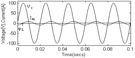
According to Fig. 5 the current Iin is shifted to the voltage Vs by α=35˚ and so the fundamental current
harmonic is in phase with this Voltage.
In general, the application of such pulses (shifted to the left by an angle a) to a controlled converter consisting of metal oxide-semiconductor field-effect transistor (MOSFET) or IGBT has two advantages:
• Input current is shifted left to the input voltage, that is, the trade-off in this work
• The most high harmonics of the input current appear in the area of high order as by the conventional SPWM, which can be eliminated by the use of a small filter.
3.Proposed Three Phase Ac-AC Converter 3.1 Circuit Description
The naturally commutated thyristor controllers introduce lower order harmonics in both the load and supply side and have low-input PF. Normally in ac choppers single pulse can be modulated to control the output or load voltage. However, the load voltage has almost square wave shapes, and therefore the load voltage and the line current has higher order harmonics. If multiple output voltage pulses are used instead of single pulse, it significantly reduces the harmonics. So, the performance of ac voltage regulators can be improved by PWM control. The Fig. 6 shows the schematic block diagram of the proposed three phase ac-ac converter employing
α-SPWM technique.
The instantaneous input phase voltages are
The instantaneous input line voltages are
Fig. 6 Block Diagram of Three Phase AC-AC Converter
The circuit configuration for one phase of the three phase ac voltage regulator for PWM control is shown in Fig. 7. The AC source offers a sinusoidal voltage VS and has the internal impedance Rg–Lg. A small Lf–Cf input
filter is used to absorb the high-order harmonics of the input current Iin. The switching power elements insulated
(4)
(5)
(6) (1)
(2)
gate bipolar transistor IGBT1 and IGBT2 with external antiparallel diodes control the load current IL, which can
flow bidirectionally. By using fast switching devices, PWM techniques can be applied to the ac voltage controllers for producing variable voltage with a better input PF.
Fig. 7 One Phase of Three Phase AC voltage regulator
3.2 Principle Of Operation
The two main modes of operation are active and freewheeling modes. A diode connected in anti-parallel with each parallel switch is used to complete the freewheeling current path .It also prevent reverse voltages from appearing across the switches. The switching sequence of the devices are given below in Table 1.
Table 1 Switching Sequence
IGBT 1 IGBT2 IGBT3 IGBT4
Vs>0 PWM OFF OFF PWM
Vs<0 OFF PWM PWM OFF
3.2.1 Active Modes:
This mode of operation occurs during both the positive and negative half cycle of the ac supply.
During the active mode of the positive half cycle, the switching power electronic element IGBT1 operates with high switching frequency. The current flows from source to load through IGBT 1, diode D2 and the inductor get charged as shown in Fig. 8(a)
In the negative half cycle active mode occurs when switching element IGBT2 is turned ON. The current flows via the load, IGBT 2, D1 as shown in Fig. 8(b)
Fig. 8(a) Active mode of Positive Half cycle Fig. 8(b) Active mode of Negative Half cycle
3.2.2 Freewheeling Modes:
Both during the positive and negative half cycle of the ac supply, freewheeling mode occurs
Similarly during the negative half cycle, when IGBT2 is off, a free-wheeling path occurs through IGBT3, the diode D4 and the load is created as shown in Fig. 8(d).
Fig. 8(c) Freewheeling mode of Positive Half cycle
Fig. 8(d) Freewheeling mode of Negative Half cycle
By controlling the duration of the conduction time (duty cycle) of IGBT1 and IGBT2, the load voltage VL and
load power can be controlled.
The other two phases are displaced by 120 ْ◌ and 240 ْ◌ respectively. These two phases also conduct similarly to the single phase described above in a three phase ac-ac converter circuit.
A converter with the structure shown in Fig. 7 can be used to control the light intensity of the light bulb to achieve high PF. Also, it can be used in induction heating, to control the speed of fans, pumps .Through the α -SPWM switching technique, the lag of the current to the voltage caused by the resistive–inductive load can be eliminated in order to improve the PF.
4. Simulation Results And Discussions
To investigate the validity of the proposed system, the proposed converter is simulated using MATLAB/SIMULINK. The three phase ac-ac converter is simulated with the three single phase’s converter in which the input voltages of the second and third phases are displaced by 120˚ and 240˚ respectively. Each single phase has the following simulation parameters Rg = 0.0262 Ω and inductance Lg = 30 µ H, filter inductance Lf =
3.5 mH, capacitor Cf = 4 µF and resistances RL =RC =0.05 V and the load values are R =40 Ω and L = 90
mH.(φL≃35)The angle by which the sine wave is shifted by α is equal to φL.
The switching frequency is chosen as a parameter in the characteristic range 4 kHz < fsw <13 kHz taking into
account the chosen Lf –Cf values. The Lf –Cf filter plays a significant role for the reactive power reduction
caused by the high harmonics.
The simulations presented in this paper study the comparison between the Input voltage & Input current characteristics, Output Voltage, Power factor.
4.1 Input Voltage and Input Current Characteristics
By the application of the SPWM pulses to the three phase ac voltage regulator, from Fig. 9(a) it is inferred that there is a lag between the input voltage and current. Furthermore by using α-SPWM technique a shifting of the fundamental current harmonic takes place in order to decrease the phase angle between this harmonic and the input voltage. It is obvious in this way that the reactive power of the fundamental harmonic is reduced and hence the lag between the input voltage and current is almost zero as in Fig. 9(b)
Fig. 9(a) Input Voltage and Current for conventional SPWM
Fig. 9(b) Input Voltage and Current for α-SPWM
4.2 Output Voltage
In this case input supply voltage is chopped into segments and output voltage level is decided by the ratio between ON/OFF. The converter output voltage for the three phases are shown in Fig. 10
Fig. 10 Output voltage
4.3 Power Factor
The power factor can be calculated by the formula
Where P is active power and Q is the apparent power
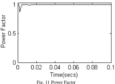
The α-SPWM technique in a three phase ac voltage regulators has a power factor of almost 0.99 as inferred from Fig. 11.
(9) (8)
Fig. 11 Power Factor
5. Conclusion
In this paper, the circuit for the three phase ac voltage regulator employing modified sinusoidal pulse width modulation technique is used and the results are obtained by simulation. Comparing the modified sine wave with a high-frequency triangular signal, switching pulses for the conduction of semiconductor power elements (IGBT) can be achieved. A shift of these switching pulses acts so that the current waveform is near to the voltage waveform, which is verified from simulation results. This critical value of the shifting angle depends on the resistive and inductive load components as well as on the active output power. The operation of this ac voltage regulator gives the following advantages: Improved load power factor due to high frequency switching, Control range is wide in terms of firing angles regardless of load power factor. The investigation leads to the conclusion that there is a value of the shifting angle for which the PF can be improved.
REFERENCES
[1] M. H. Rashid,”Power Electronics: Circuits, Devices and Applications”, 2nd ed. Upper Saddle River, NJ:Prentice Hall, 1993.
[2] B. W. Williams, “Asymmetrically modulated AC choppers,”IEEE Trans. Ind. Electron., vol. IE-29, pp. 181– 185, Aug. 1982.
[3] S. A. Bhat and J. Vithayathil, “A simple multiple pulse width modulatedAC chopper,”IEEE Trans Ind.Electron. vol. IE-29, pp. 185–
189, Aug.1982.
[4] G. H. Choe, A. K. Wallace, and M. H. Park, “An improved PWMtechnique for AC choppers,”IEEE Trans. power Electron., vol. 4,
pp.496–505, Oct. 1989.
[5] D. A. Deib and H. W. Hill, “Optimal harmonic reduction in ac/ac chopper converters,” inProc. IEEE PESC’93, 1993, pp. 1055–1060.
[6] M. Mazzuccheli, L. Puglisi, G. Sciutto, and P. Tenti, “Improvingthe performance of AC/AC static converters with high frequency
ACchopper control,” inProc. POWERCON 9, 1982, vol. I-3, pp. 1–9.
[7] D. H. Jang, J. S. Won, and G. H. Choe, “Asymmetrical PWM method ofac chopper with improved input power factor,” inProc. IEEE
PESC’91,1991, pp. 838–845.
[8] P. D. Ziogas., D. Vincenti, and D. Joos, “A practical PWM ac chopper topology,” inProc. IEEE IECON’91,1991, pp. 880–887.
[9] N.A Ahmed, K. Amei, M.Saku,”A new configuration of single-phase symmetrical PWM AC chopper voltage controller”, IEEE Trans.
Ind. Electron., 1999, 46, (5), pp. 942–952
[10] J.Spangler, A. Behera, “A comparison between hysteretic and fixed frequency boost converters used for power factor correction”.
Proc. IEEE Applied Power Electronics Conf. Expo, 1993, pp. 281–286
[11] K.Georgakas, A. Safacas,”Power factor improvement of an AC–DC converter via appropriate sPWM Technique”.MED07, Athens,
Greece, 27–29 June 2007, paper T26–024
[12] Georgakas K., Safacas A.: “Modified sinusoidal pulse-width modulation operation technique of an AC–AC single-phase converter to