2nd International Conference on Current Research Trends in Engineering and Technology © 2018 IJSRSET | Volume 4 | Issue 5 | Print ISSN: 2395-1990 | Online ISSN : 2394-4099 Themed Section: Engineering and Technology
Comparison of Performance Based Plastic Design Method and Force
Based design Method for Seismic Design of Zipper Braced Frame
Jaimin K Shah*
1, Dr. S.P. Dalal
21*P.G Student, GTU, SVIT Vasad, Anand, Gujarat, India 2Associate Professor, GTU, SVIT Vasad, Anand, Gujarat, India
ABSTRACT
This paper present comparative study of seismic design consideration and design methodologies for steel Zipper braced frame by force based design method and performance based plastic design method. In force based design method (FBD), lateral force distribution are based on results of elastic- response studies. Performance based plastic design method (PBPD) is mainly based on pre - selected target drift and yield mechanism as performance criteria. PBPD depends on strong column- weak beam theory in which failure pattern is pre-determined. Zipper braced frame is similar to chevron frame, in which a zipper column is added between story beams to avoid use of deep beams.
Keywords: Performance based plastic design, Force based design, zipper braced frame, Strong column-weak beam
I.
INTRODUCTIONCurrent seismic design approach (FBD) is generally based on elastic analysis. In the current Indian design practice, design base shear is calculated from code specified spectral acceleration, with the assumption that structure to behave elastic. It is also reduced by response reduction factor R. the design forces is also influenced by importance factor I, based on occupancy. By the use of these parameters lateral forces are found, member size will be selected from design results and then check for drift and deflection of the structure is done, which must be within an acceptable limit. Sometime the structures experienced high earthquake forces however, the structures designed by such procedures have been found to undergo inelastic deformations in a somewhat „uncontrolled‟ manner. This may results undesirable and unpredictable behaviour, sometimes total collapse, or difficult and costly repair works. So the societal requirements are pushing the practice to achieving
higher levels of performance, safety and economy, including life-cycle costs.
Zipper braced frame is similar to chevron (Inverted V braced frame). A zipper column is added in between the story beams of chevron braced frame. In chevron braced frame, one of the braces resist the lateral load in tension and the counter one resist in compression. After buckling of brace in compression, brace loses most of its axial load capacity while the tension braces retains it, which results in an unequal distribution of the lateral force between the braces. Due to unequal distribution a vertical component emerges in addition to the horizontal component of the resultant of the brace forces. This vertical component might causes large bending moment demand at the mid-span which might create a plastic hinge at the mid- span, soft storey and collapse. Adding zipper column at the mid- span on two story beams transfer the vertical force emerging after the buckling of the compression braces to the adjacent story braces that still retain their axial load capacity. By using zipper column use of deep beams is avoided and uniform drift demand is obtained.
II. ANALYSIS AND DESIGN PROCEDURES
The Performance-Based Plastic Design Method has been retrieved from the suggestions by Goel and Chao, 2009. In FBD Method as per Indian Code of practice, the structure is designed for force (strength) and checked for displacement (serviceability).In PBPD Method the structure is designed for pre-determined target drift and yield mechanism. This prevents total collapse of the structure. As there are no guidelines available for PBPD Method in Indian code, it is suggested that the design base shear and distribution of lateral force can be done based on suggestions given by Chao, 2007. The calculation of forces and moments is also done based on suggestions given by Chao, 2006.
A Lateral Force Calculation
1) Lateral force calculation and distribution in FBD method:
The lateral seismic loads to be applied on the structure are calculated based on the Elastic Design Spectra prescribed in IS 1893:2002 which gives the design spectral acceleration, “Sa” of the structure having time period “Tn” due to elastic response (μ = 1).
The total base shear in this method is given by [IS 1893:2016/clause 7.6.1]
VB = Ah • W
In Which W is the total seismic weight of the structure and Ah is the horizontal seismic co-efficient. [IS 1893: 2016 /clause 6.4.2]
Ah =
This Base Shear is distributed among the floors, which is known as lateral force distribution at each floor level, “Qi” as per [IS 1893: 2016/clause 7.6.3]
2) Lateral Force calculation and distribution in PBPD method:
The Performance Based Plastic Design Method for Concentrically Braced Frames can be used for the Indian codal provisions by following the analysis procedure as proposed by Chao and Goel, because it is based on equilibrium equations available at the time of failure of the structure.
The total Base Shear in this method is calculated based on work energy equation which is expressed as
VB =
The Ductility factor is related to energy modification factor “γ” in the following way by applying the Energy balance concept as proposed by Lee and Goel.
Where,
= Structural ductility Factor Rµ = Strength Reduction factor
(and )= Height of level i (and roof) measured from base
Wi (and Wn) = Seismic weight of level i (and roof) = the selected global inelastic drift ratio of the structure
In PBPD method, first the lateral force at roof level (Qn) is calculated as
Then the lateral force at each floor (Qi) is distributed with reference to the force of roof.
B. Design of Zipper Braced Frame
The design of Zipper braced frame includes two steps. In first step the frame is design as conventional inverted V braced frame. In second step, the zipper column is added and other elements are redesigned except top story braces. Step one of design of Zipper Braced frame is as follows:
1) Analysis and design of bracings as per PBPD and FBD method:
Bracing section in PBPD method should satisfy following criteria:
Vi
Where,
= Tension yielding state load and = = Post buckling state load and =
= yield stress
= Gross area of the section
= Angle of bracing member with horizontal = Partial safety factor for material strength
In FBD method, proper design axial force for bracing members is found out first and then the bracings are to be designed as per clause 6.1 and clause 7.1 of IS-800:2007.
2) Analysis and design of beams as per PBPD and FBD method:
In PBPD Method beams intersected by the braces should be designed assuming that no gravity loads are resisted by braces. The beams should also be designed to support vertical and horizontal unbalanced loads resulting from the force difference in the tension and compression braces as shown in figure 1.
Figure 1. Beam Design Forces for a Chevron Type CBF Axial Load:
Beam Moment:
After getting the proper design bending moments, shear force and axial force for beam members by using both the methods as discussed above, beams are to be designed as per IS-800:2007 clause 8.2 for flexure and clause 8.4 for shear and checked for deflection as per clause 5.6.1.
3) Analysis and design of columns as per PBPD and FBD method:
In PBPD method columns, only axial loads are consider while designing and are design according to IS 800:2007 clause 7.1 and in FBD method columns are design as beam column according to IS 800: 2007 clause 9.3 In PBPD columns are designed for two limits state 1) Pre- buckling- when no brace buckling occurs and no unbalanced force occurs in beam. 2) Post - buckling - when brace - ultimate state and unbalanced force occurs in the beams
(a) Interior
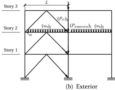
(b) Exterior
Figure 2 (a & b) Axial force components for brace pre-buckling limit state
Pre - buckling State - Typical exterior column:
𝑃=(𝑃𝑡𝑟𝑎𝑛𝑠𝑣𝑒𝑟𝑠𝑒)𝑖+ (𝑃𝑏𝑒𝑎𝑚)𝑖+(𝑃𝑐𝑟 sin𝛼)𝑖+1
Typical Interior column:
𝑃=(𝑃𝑡𝑟𝑎𝑛𝑠𝑣𝑒𝑟𝑠𝑒)𝑖+ +(𝑃𝑐𝑟 sin𝛼)𝑖+1
(b) Exterior
Figure 3 (a & b) Axial force components for brace post-buckling limit state
Post buckling State-
Typical exterior column:
𝑃=(𝑃𝑡𝑟𝑎𝑛𝑠𝑣𝑒𝑟𝑠𝑒)𝑖+ (𝑃𝑏𝑒𝑎𝑚)𝑖+(𝑃𝑐𝑟 sin𝛼)𝑖+1+0.5𝐹𝑣
Typical interior column:
𝑃=(𝑃𝑡𝑟𝑎𝑛𝑠𝑣𝑒𝑟𝑠𝑒)𝑖+ +(𝑃𝑐𝑟sin𝛼)𝑖+1+0.5𝐹𝑣
Step 2 of adding of Zipper Column and redesign other component except top story brace.
4) Design of Zipper Column:
Zipper struts shall be designed to resist the vertical unbalanced forces generated by the braces and zipper element located on the level below. The brace forces shall be taken as 1.1* * for the brace in tension and 0.3* * for the brace in compression.
Area of braces =
Where,
Ty =1.1 Ag Fy (tensile yield strength of tension brace) Cu = 0.3 Ag Fcr (residual post-buckling strength),
α = angle of diagonal brace,
Fy = yield strength of the zipper column.
The above equation is given by Jeongjae Kim et al. (2008)
Figure 4 Post-buckling vertical unbalance force (Jeongjae Kim et al. (2008) )
After adding Zipper column the top story are redesigned in PBDP method are design to resist for 2 times lateral force. Beam in both the methods are redesigned and required bending strength shall be determined using the maximum bending moment by the effect of the un- factored vertical loading.
Figure 5 Full height Collapse mechanism of Zipper frame
IV. SUMMARY AND CONCLUSION
zonation of our country and is based on the previous earthquake data available. The importance factor (I), depends on the functional use of the structure. From the above information it is clearly understood that the design forces derived from the current code are quite assumptive as the factors governing the design of forces are mainly based on engineering judgments. Because of these reasons, the structures may undergo large inelastic deformations during major earthquakes. In PBPD method drift control and yielding is taken into account at the beginning In FBD method Sa/g value is considered for ductility factor µ=1using Elastic design spectra, where as in PBPD method Sa inelastic / g value can be determined Sa inelastic/g value can be determined for desired ductility factor by applying reduction factors proposed by J.Vaseghi Amiri et al. etc. In FBD method, analysis is done for the frame as statically indeterminate and moments & forces are calculated using M.D. Method, kani‟s method or other standard method (matrix method if software is used), whereas in PBPD method, analysis is simply carried out with the help of basic equations of equilibrium as three hinges in bracings, two in zipper column, two hinges are formed in beam and one at base of each column, making it a determinate structure as per Chao and Goel 2006.
Zipper column added in chevron braced frame result in uniform drift demand, avoids use of deep beams and failure due to unbalanced vertical force which may cause hinge formation, soft story and collapse which is prevented , another advantage of the ZBF is that the clear force path make design more straight forward.
V. REFERNCES
[1].
H. Akiyama, “Earthquake resistant limit state design for cylindrical liquid storage tanks”, 10th world conference on earthquake engineering, 1992.[2].
George W. Housner, “The behavior of inverted pendulum structures during earthquakes”,Bulletin of the seismological society of America, 1963. Vol. 53, No. 2, 403-417.
[3].
Sutat Leelataviwat, S. C. Goel and BozidarStojadinovic, “Towards performance-based
seismic design of structures”, Earthquake spectra, 1999. Vol. 15.
[4].
Subhash C. Goel, Shih-Ho Chao, Sutat Leelataviwat and Soon-Sik Lee, “Performance-based plastic design method for earthquake resistant structures”, 14th World conference on earthquake engineering, 2008.[5].
Khatib, I. F., Mahin, S. A., & Pister, K. S. (1988) “Seismic behavior of concentrically braced steel frames “ (Report No. UCB/EERC-88/01).Berkeley, CA: University of California,
Earthquake Engineering Research Center.
[6].
Javad Vaseghi Amiri , “Ductility Reduction Factor for Zipper Braced frame “, EuropeanJournal of Environmental and
CivilEngineering·November2016
[7].
Chuang-Sheng Yang , Roberto T. Leon, Reginald DesRoches,”Design and Behaviour of Zipper braced Frame”, Engineering Structures 30 (2008) 1092-1100 .[8].
Jeongjae Kim , Chunhee Cho,Kyungkoo Lee and Cheolho Lee,” Design of Zipper Column in Inverted V Braced Steel Frames” , The 14th World Conference on Earthquake Engineering ,October 2018.[9].
Shih-Ho Chao, S. C. Goel and Soon-Sik lee, “A seismic design lateral force distribution based on inelastic state of structure”, Earthquake spectra, 2007. Vol. 23, 547-569.[10].
Shih-Ho Chao, M. Reza Bayat and Subhash C. Goel, “Performance-based plastic design of steelconcentric braced frames for enhanced
confidence level”, 14 th World conference on earthquake engineering, 2008.
tall and special buildings, 2009. Vol. 19, 115-137.
[12].
Tomaz Vidic, Peter Fajfar and Matej Fischinger, “Consistent inelastic design spectra: strength and displacement “.Earthquake engineering and structural dynamics ,1994,Vol 23, 507-521.[13].
Miranda, E ., & Bertero, V (1994) ,”Evaluation of strength reduction factors for earthquake - resistant design “, Earthquake Spectra, 10, 357-379.[14].
IS 1893-2016, Criteria for Earthquake Resistant Design of Structures[15].
IS 800:2007, General Construction Steel-Code of Practice[16].
Chokshi H K, Vaidya K K, Dalal S. P. “Comparison of Force-Based Design Method and Performance-Based Plastic Design Method for Seismic Design of Steel Concentric Braced Frames”, International Journal of AdvanceEngineering and Research Development
(IJAERD) Special Issue SIEICON2017, April -2017,e-ISSN: 2348 - 4470 , print-ISSN:2348-6406.