Performance Based Evaluation of Response Reduction Factor of Steel
Staging Water Tank
Parth N. Patel1, Jignesh A. Amin2
1PG Student, Department of Civil Engineering, Sardar Vallabhbhai Patel Institute of Technology, Vasad
Gujarat, India
2Professor, Department of Civil Engineering, Sardar Vallabhbhai Patel Institute of Technology, Vasad
Gujarat, India
ABSTRACT
Steel staging elevated water tanks are critical structures that are expected to remain operational even after sever earthquakes. The seismic design codes/standards of most countries allow the nonlinear response of a structure through a ‗seismic response factor‘ (R). This factor permits a designer to use a linear elastic force based design while accounting for nonlinear behaviour and deformation limits. In this paper systematic approach is used to determine the seismic response reduction factor of steel staging elevated water tank and designed and detailed using relevant IS standards. The study water tanks are analysed using nonlinear static pushover analysis to obtain the capacity/pushover curve. The response reduction factor of considered tanks are evaluated at two performance limit namely member level and structural level respectively.
Keywords: Steel staging water tank, nonlinear analysis, over strength factor, ductility factor, response reduction factor
I. INTRODUCTION
The liquid containing steel storage tanks are significant structure in water distribution network. Tanks should remain functional even after major earthquakes. Earthquake could induce large horizontal and overturning forces in steel staging water tanks. Such tanks are extremely vulnerable to damage in earthquakes due to their basic configuration involving large mass concentrated at top with relatively slender supporting system. When the condition of water tank is full, earthquake forces govern the design of these structures in zones of high seismic activity. It is important to ascertain that the essential requirement such as water tank is not damaged during earthquakes.
engineering judgment. The values of response reduction factor of elevated water tank adopted by difference codes/standards are summaries in Table 1. Present research does not show any detailed groundwork on which a value of 3.5 is fixed for steel staging elevated water tanks in the Indian standard IS:1893(Part-2):2014.
Mondal et al. [1] estimated that values of response reduction factor for RC moment frame structure designed and detailed using the Indian codes for earthquake and ductile detailing. Using nonlinear analysis of RC frame author concluded that the value of ‗R‘ factor is higher than real value suggested in IS 1893(Part-2):2002, which is not acceptable. Kim and Choi [2] performed response reduction factor of SCBF‘s and OCBF‘s by nonlinear analysis of model structures with various stories and span length. He observed that in SCBF‘s the response reduction factor is turned out to be smaller than the code indicated value of 6.0 in most model structures excepting the three-story structures. The response reduction factors were less than the suggested code value of 5.0 in all OCBF model structures. Mahmoudi and Zaree [3] are concluded that the over strength and R-factor of BRBFs decreased with an increase in the height of the building. And they are also noted that the over strength and R-factors increased with an increases the number of bracing bays. Manek and Jivani [4] observed that base shear decreases as the staging height increases. They also observed that R factor was considerably affected by the fundamental time period of water tank. Khatavkar et. al [5] used displacement control pushover analysis and applied the earthquake forces at CG of structure and generate pushover curve base shear vs. roof displacement. They observed that ductility factor was important for RC frame whereas over strength factor was significant for Steel frame structure. Tamboli and Amin [6] observed the result so that R-factor of
asymmetric RC frame was substantially affected by arrangement of the bracing system and they were also added that bracing or shear wall with alternate bays increases the value of R-factor compared to the bare RC frame.
One constant R-value for elevated water tank can‘t reflect the expected inelastic behaviour of elevated water tanks supported on various types of soil. The aim of this present study is to determine the seismic response factor for steel staging water tank with different height of staging and compared these values with the value suggested in the seismic design code.
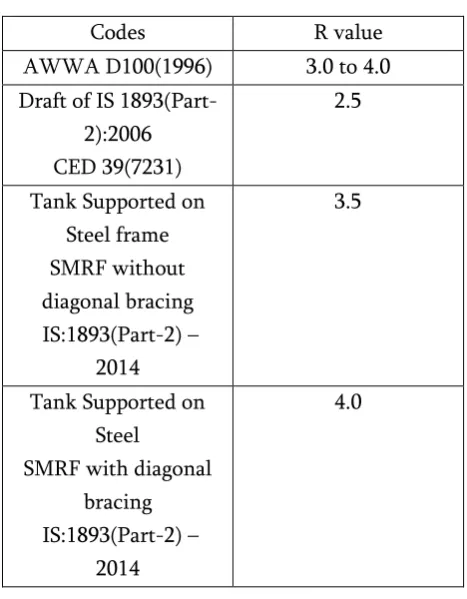
Table 1 value of 'R' from different codes
Codes R value
AWWA D100(1996) 3.0 to 4.0 Draft of IS
1893(Part-2):2006 CED 39(7231)
2.5
Tank Supported on Steel frame SMRF without diagonal bracing IS:1893(Part-2) –
2014
3.5
Tank Supported on Steel
SMRF with diagonal bracing IS:1893(Part-2) –
2014
4.0
II. COMPONENT OF ‗R‘ FACTOR
R = Rs X Rμ X RR (1)
A. Strength factor
Strength factor (Rs) is account for the yielding of a structure at load higher than the design load due to various partial safety factors, strain hardening, oversized members, and limitation of steel. Non-structural elements are also contribute to the over strength factor. The over strength factor generally vary with seismic zones, height of structure and design gravity loads/capacity of water tank. The strength factor (𝑅S) is the ratio of maximum base
shear (Vu) to the design base shear (Vd).
Rs = (2)
B. Ductility factor
The seismic response parameters of displacement capacity, ductility and ductility ratio are closely inter-related. Displacement ductility ratio is generally defined as the ratio of maximum displacement to the displacement at yield.
Miranda and Bertero (1994) represented the R-μ-T relationships developed by a number of researchers including Newmark and Hall (1982), Riddell and Newmark (1979), and Krawinkler and Nassar (1992), in addition to developing general Rμ-μ-T equations for rock, alluvium, and soft soil
sites. The Miranda and Bertero equations presented were developed using 124 ground motions recorded on a wide range of soil conditions as per below:
Rμ = (3)
Where: For rock sites:
Φ =
) ) (4)
For alluvium sites:
Φ =
) ) (5)
For soft soil sites:
Φ =
⁄ ) )
(6) Where, Tg is the predominant period of the
ground motion.
C. Redundancy Factor
A redundant seismic framing system should composed of vertical lines of framing system and each can be detailed and designed to transfer seismic-induced inertial forces to the foundation. Yielding at one location in the structure does not specify yielding of the whole structure. Hence, the load distribution due to redundancy of the structure which is required additional safety margin. Steel structural systems with lateral load resisting frames are normally considered as redundant structure, as each of the seismic frames is designed to transfer the seismic forces to the soil. Following the conservative assumption, RR =
1.0 is used in this study.
D. Structural performance limit
for braced steel frames as per collapse prevention defined in FEMA 356 given in Table 4.
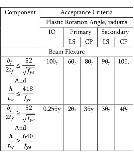
Table 2 Acceptance Criteria for Nonlinear Procedures—Structural Steel
Component Acceptance Criteria Plastic Rotation Angle, radians
IO Primary Secondary LS CP LS CP Beam Flexure
√ And
10θy 6θy 8θy 9θy 10θy
√ And
0.25θy 2θy 3θy 3θy 4θy
Table 3 Acceptance Criteria for Nonlinear Procedures—Structural Steel
Component Acceptance Criteria Plastic Rotation Angle, radians
IO Primary Secondary LS CP LS CP Column Flexure
√ And
10θy 6θy 8θy 9θy 10θy
√ And
0.25θy 2θy 3θy 3θy 4θy
Table 4 Structural Performance Levels and Damage-Vertical Frames
Elements Type Structural Performance Level
Braced Steel Frame
Drift CP LS IO
2% 1.5% 0.5 %
III. DESCRIPTION AND MODELLING OF WATER TANK
In present study, ‗R‘ factor of rectangular steel staging water tank having a capacity of 250m3
evaluated considering medium soil. The yield stress of steel taken as Fe250. The tank is situated at seismic zone V. The typical configuration of staging system at the base is shown in fig. The brief structural detailing and description of considered elevated water tank is given in Table 5 and Table 6.
Fig. 2 24m height of staging
Fig. 3 28m height of staging
Table 5 Description of water tank
Capacity 250m3
Height Of Staging 20m,24m,28m
Type of Soil Medium
Earthquake Zone V
Length Of Container 7.5 m Width Of Container 7.5 m
Height Of Container 5 m
Free Board 0.5 m
Roof Slab Thickness 6 mm
Wall Thickness 6 mm
Floor Slab Thickness 10 mm
Main Beam 5 m
Secondary Beam 5 m
Braces 5 m
Column 4 m c/c
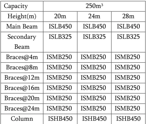
Table 6 Steel section detail of water tank
Capacity 250m3
Height(m) 20m 24m 28m
Main Beam ISLB450 ISLB450 ISLB450 Secondary
Beam
ISLB325 ISLB325 ISLB325
Braces@4m ISMB250 ISMB250 ISMB250 Braces@8m ISMB250 ISMB250 ISMB250 Braces@12m ISMB250 ISMB250 ISMB250 Braces@16m ISMB250 ISMB250 ISMB250 Braces@20m ISMB250 ISMB250 ISMB250 Braces@24m ISMB250 ISMB250 ISMB250 Column ISHB450 ISHB450 ISHB450
Following are the load combinations considered for design of steel staging water tank according to IS 1893:2016.
1.2(DL+LL+WL+EQ) 1.2(DL+LL+WL-EQ)
IV. PUSHOVER ANALYSIS AND RESULT In order to achieve the objective, the following pushover procedure was adopted:
Developing a three dimensional model of steel staging water tank.
Apply gravity loads, live loads, water load, etc. to the model.
To apply appropriate support condition as a fixed base. Provide a rigid link at the CG of the container.
Application of static lateral load induced due to earthquake, at CG of the container. Assign hinge properties which are given
in SAP 2000 nonlinear as per FEMA-356 to the frame elements. For the beam that yields based upon the steel beam flexure P-M3.
and bending moment for column flexure assigning P-M2-M3 hinges.
Define static pushover case. In the first case, gravity load is applied to the structure. In second case lateral load. Push the structure using the load patterns
of static lateral loads and displacements larger than those associated with target displacement using static pushover analysis.
Develop a pushover curve and estimating the force and deformations in each element at the level of displacement corresponding to target displacement.
Sap 2000 V18 is used to perform nonlinear static pushover procedure of considered tank. The steel frames are modelled as 3D frame element with centre line dimension as per IS:800-2007. Different parameters such as weight of staging, weight of container, weight of convective and impulsive masses, C.G of tank are computed as per IS 1893(Part-2):2014. The diaphragm action of a slab was considering by assigning a rigid link at the floor level of container.
A. Estimation of ‗R‘ Factor for 20m height 1) Over strength factor
Design base shear (As per EQ calculation) Vd = 124.8kN
Maximum base shear Vu = 401.7kN Using equation for strength factor, as given in ATC-19
Rs = Vu/Vd = ⁄
Rs = 3.21
2) Ductility factor
Maximum drift capacity Δm = 252mm
(From pushover curve)
Yield drift Δy =200mm(From
bilinierization)
Using equation for displacement ductility ratio, given in ATC-19.
μ = Δm / Δy = 252 / 200 = 1.25
Using equation for ductility factor, derived by Miranda and Bertero
𝑅
Φ for medium soil
= )
Ti (Impulsive time period) = 1.71 seconds
= 0.867
3) Redundancy factor
The values of redundancy factor (RR) are
dependent on the number of vertical framing participate in seismic resistance. (ATC19)
RR = 1
4) Response reduction factor R = Rs X 𝑅 X RR
= 3.23 X 1.3 X 1
= 4.19
From the pushover analysis, the base shear (V) vs. roof displacement (Δmax) curve of the structure is
used to obtain ‗R‘ factor of the frame element, which is called static capacity curve. In static nonlinear procedure estimation of targeted displacement is required. The target displacement works as an estimate of the maximum displacement of the selected joint of the structure subjected to design earthquake. The node is taken with the centre of mass at CG of container is used as target displacement.
limits PL1 and PL2 are considered to evaluate R factor.
Fig. 4 Pushover curve for 20m height
Fig. 5 Pushover curve for 24m height
Fig. 6 Pushover curve for 28m height
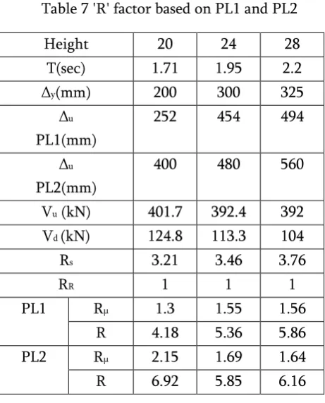
Table 7 'R' factor based on PL1 and PL2
Height 20 24 28
T(sec) 1.71 1.95 2.2
Δy(mm) 200 300 325
Δu
PL1(mm)
252 454 494
Δu
PL2(mm)
400 480 560
Vu (kN) 401.7 392.4 392
Vd (kN) 124.8 113.3 104
Rs 3.21 3.46 3.76
RR 1 1 1
PL1 Rμ 1.3 1.55 1.56
R 4.18 5.36 5.86
PL2 Rμ 2.15 1.69 1.64
R 6.92 5.85 6.16
V. CONCLUSION
In this study the ‗R‘ factor of steel staging elevated water tank having different staging heights are evaluated. This study may prove useful in formulating guidelines for evaluation of ‗R‘ factor for seismic design of steel staging elevated water tank for medium soil. The important conclusions of present study are as follows:
factor, time period, base shear and ductility factor of water tank.
For PL1, the over strength factor, ductility factor and response reduction factor increases with the increase of the fundamental impulsive time period of water tanks.
The R values corresponding to PL1 and PL2 for the study elevated water tanks having 20m,24m and 28m staging height ranges from 4.18 to 6.92 , and are all higher than IS1893(part-2):2014 specified value of (R=3.5) for steel staging elevated water tanks.
VI. REFERENCES
[1].
Jinkoo Kim and Hyunhoon Choi ―Response modification factors of chevron-braced frames‖ Journal of Engineering Structures, Volume 27, Issue 2, pp.285-300, 2005[2].
Apurba Mondal, Siddhartha Ghosh and G.R. Reddy ―Performance-based evaluation of the response reduction factor for ductile RC frames‖ Engineering Structures, vol. 56, pp. 1808-1819, 2013[3].
Mostafa Masoudi, Sassan Eshghi,MohsenGhafory-Ashtiany ―Evaluation of response modification factor (R) of elevated concrete tanks‖ Engineering Structures, vol.39, pp. 199-209, 2012
[4].
R. Gateh, M.R. Kianoush, and W. Pogorzelski ―Seismic response factors of reinforced concrete pedestal in elevated water tank‖ Engineering Structures, vol. 87, pp. 32-46, 2015[5].
Mr. Bhavin Patel and Mrs. Dhara Shah ―Formulation of Response Reduction Factor for RCC Framed Staging of Elevated Water Tank using StaticPushover Analysis‖ World Congress on Engineering, vol. 3, 2010
[6].
Y. S. Salem and M. A. M. Nasr ―Evaluating response modification factors of Open-frames Steel Platforms‖ Tenth U.S. National Conference on Earthquake Engineering, 2014[7].
A.S.Khatavkar, A.P.Ghadi and Prof P.R. Barbude ―A study on response reduction factor of RC water tank‖ International Conference on Quality Up-gradation in Engineering, Science and Technology, vol. 2, issue 5, 2015[8].
Kruti J. Tamboli, J A. Amin, ―Assessment Of Response Reduction Factor For Asymmetric RC Frame Building‖International Journal of Advance
Engineering and Research Development, Volume 2,Issue 6, June -2015
[9].
Tejas Patel, Jignesh Amin and Bhavin Patel, ― Evaluation of response reduction factor of RC framed staging elevated water tank using static pushover analysis‖ International journal of civil and structural engineering, vol. 4, 2014[10].
IS 1893 Part 1, ―Indian standard criteria for earthquake resistant design of structures‖, Part 1:General provisions and buildings, Bureau of Indian standards, New Delhi, India, 2016[11].
IS 1893 Part 2, ―Indian standard criteria for earthquake resistant design of structures‖ Part 2:Liquid retaining tanks, Bureau of Indian standards, New Delhi, India, 2014[12].
IS 800, ―General construction in steel-Code of practice‖ Bureau of Indian standards, New Delhi, India, 2007[13].
ATC 19, ―Structural response modification factor‖ Applied Technology Council,Engineering Research, California United states, 1995