Cancellous bone and theropod dinosaur
locomotion. Part I
—
an examination
of cancellous bone architecture in the
hindlimb bones of theropods
Peter J. Bishop1,2,3,4, Scott A. Hocknull1,2,5, Christofer J. Clemente6,7, John R. Hutchinson8, Andrew A. Farke9, Belinda R. Beck2,10,
Rod S. Barrett2,3and David G. Lloyd2,3
1Geosciences Program, Queensland Museum, Brisbane, QLD, Australia
2School of Allied Health Sciences, Griffith University, Gold Coast, QLD, Australia
3Gold Coast Orthopaedic Research, Engineering and Education Alliance, Menzies Health Institute
Queensland, Gold Coast, QLD, Australia
4Current affiliation: Structure and Motion Laboratory, Department of Comparative Biomedical
Sciences, Royal Veterinary College, Hatfield, Hertfordshire, UK
5School of Biosciences, University of Melbourne, Melbourne, VIC, Australia
6School of Science and Engineering, University of the Sunshine Coast, Maroochydore,
QLD, Australia
7School of Biological Sciences, University of Queensland, Brisbane, QLD, Australia
8Structure and Motion Laboratory, Department of Comparative Biomedical Sciences, Royal
Veterinary College, Hatfield, Hertfordshire, UK
9Raymond M. Alf Museum of Paleontology at The Webb Schools, Claremont, CA, USA
10Exercise and Human Performance, Menzies Health Institute Queensland, Gold Coast, QLD,
Australia
ABSTRACT
This paper is thefirst of a three-part series that investigates the architecture of cancellous (‘spongy’) bone in the main hindlimb bones of theropod dinosaurs, and uses cancellous bone architectural patterns to infer locomotor biomechanics in extinct non-avian species. Cancellous bone is widely known to be highly sensitive to its mechanical environment, and has previously been used to infer locomotor
biomechanics in extinct tetrapod vertebrates, especially primates. Despite great promise, cancellous bone architecture has remained little utilized for investigating locomotion in many other extinct vertebrate groups, such as dinosaurs. Documentation and
quantification of architectural patterns across a whole bone, and across multiple bones, can provide much information on cancellous bone architectural patterns and variation across species. Additionally, this also lends itself to analysis of the musculoskeletal biomechanical factors involved in a direct, mechanistic fashion.
On this premise, computed tomographic and image analysis techniques were used to describe and analyse the three-dimensional architecture of cancellous bone in the main hindlimb bones of theropod dinosaurs for the first time. A
comprehensive survey across many extant and extinct species is produced, identifying several patterns of similarity and contrast between groups. For instance, more stemward non-avian theropods (e.g. ceratosaurs and
tyrannosaurids) exhibit cancellous bone architectures more comparable to that present in humans, whereas species more closely related to birds (e.g. paravians) exhibit architectural patterns bearing greater similarity to those of extant birds. Submitted8 January 2018
Accepted18 September 2018 Published31 October 2018
Corresponding author
Peter J. Bishop, pbishop@rvc.ac.uk
Academic editor
Mathew Wedel
Additional Information and Declarations can be found on page 86
DOI10.7717/peerj.5778
Copyright 2018 Bishop et al. Distributed under
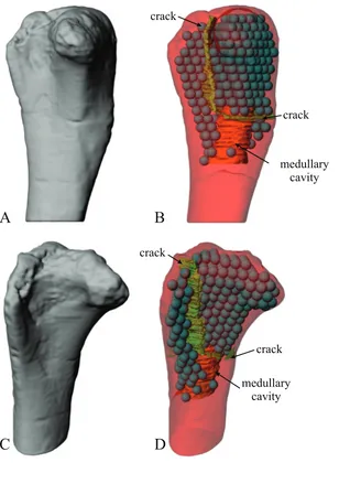
Many of the observed patterns may be linked to particular aspects of locomotor biomechanics, such as the degree of hip or kneeflexion during stance and gait. A further important observation is the abundance of markedly oblique trabeculae in the diaphyses of the femur and tibia of birds, which in large species produces spiralling patterns along the endosteal surface. Not only do these observations provide new insight into theropod anatomy and behaviour, they also provide the foundation for mechanistic testing of locomotor hypotheses via musculoskeletal biomechanical modelling.
Subjects Evolutionary Studies, Paleontology, Zoology
Keywords Cancellous bone, Theropod, Bird, Locomotion, Biomechanics
INTRODUCTION
Background
Perhaps more than any other group of extinct vertebrates (except hominin primates), dinosaurs have been the subject of extensive research into a wide variety of aspects concerning their palaeobiology. One such aspect is their manner of locomotion, which has often been the topic of much debate. Locomotion has played an important role in arguments surrounding dinosaur physiology, behaviour and palaeoecology
(Alexander, 1989;Bakker, 1980,1986;Bell & Snively, 2008;Horner & Lessem, 1993;
Molnar & Farlow, 1990;Ostrom, 1969;Paul, 1988,2008;Pontzer, Allen & Hutchinson,
2009;Thomas & Farlow, 1997;Thulborn, 1984). Movement has also been important to
understanding dinosaur evolution. For example, approximately three-quarters of the features that distinguish dinosaurs from other animals relate to their erect
(parasagittal), ancestrally bipedal posture and locomotion (Brusatte, 2012;Novas, 1996). Furthermore, much of dinosaur evolution was accompanied by major changes in locomotor morphology, and by inference, behaviour (Carrano, 2000,2005;Gatesy, 2002;
Gatesy & Middleton, 1997;Hutchinson & Allen, 2009;Maidment et al., 2014;
Middleton & Gatesy, 2000;Novas, 1996).
The only primary evidence of dinosaur locomotion available to palaeontologists is the fossils left behind, either body fossils (bones) or trace fossils (footprints and trackways). Fossil footprints and trackways are the most direct line of evidence of locomotion in extinct dinosaurs (Farlow et al., 2012;Gatesy et al., 1999;Gillette & Lockley, 1989;
Lockley, 1991;Thulborn, 1990). However, footprints and trackways do not provide
direct insight into the movement or coordination of individual limb segments except for the distal limb; moreover, they cannot be definitively assigned to a particular
trackmaker (Hutchinson & Gatesy, 2006;Lockley, 1991;Thulborn, 1990). In contrast, the associated bones of the animal’s skeleton can be positively assigned to a given species, and if preserved well can provide insight into parts of the animal that never touched the substrate.
dinosaurs. These studies have typically focused on externally visible features, such as bone shapes or proportions (Carrano, 1998,2001,2005;Christiansen, 1999;Coombs, 1978;
Gatesy, 1991b;Gatesy & Middleton, 1997;Maidment & Barrett, 2014;Maidment et al.,
2012), joint range of motion (Mallison, 2010a,2010b;Paul, 1998) or geometrical relationships between inferred muscle lines of action and joints (Bates, Benson &
Falkingham, 2012;Carrano, 2000;Hutchinson et al., 2005,2008;Maidment et al., 2014;
Russell, 1972). The insight such studies can provide are usually only general, often
having little bearing for understanding the posture or gait of any one species, and moreover carry the caveat of unknowns of soft tissue influences, which may be substantial (Bonnan et al., 2010;Hutchinson & Gatesy, 2006;Tsai & Holliday, 2015). Additionally, these studies may only be able to clarify the range of potential locomotor behaviours used by extinct dinosaurs, rather than the reconstruct the behaviors actually used.
A further line of osteological evidence that has been frequently investigated is the cross-sectional geometry of the mid-shaft of limb bones (Alexander, 1985,1989,
1991;Christiansen, 1997,1998;Cubo et al., 2015;Fariña, Vizcaíno & Blanco, 1997;
Farke & Alicea, 2009;Farlow, Smith & Robinson, 1995;Heinrich, Ruff &
Weishampel, 1993;Lovejoy et al., 2002;Mazzetta, Fariña & Vizcaíno, 1998;Wilson &
Carrano, 1999). The implicit assumption of such enquiry is that the manner in which
cortical bone is distributed around a diaphyseal cross-section is related to the magnitude and direction of bending and torsional stresses it experiences (Biewener,
1992;Brassey et al., 2013;Wainwright et al., 1976). Therefore, the geometry of a limb
bone’s cross-section at midshaft may provide insight into whole-bone loading mechanics, and by extension, locomotor behaviour. However, a growing body of experimental evidence indicates that there is no simple correlation between cortical bone morphology and aspects of bone loading, such as bending direction (Bertram &
Biewener, 1988;Biewener & Taylor, 1986;Butcher et al., 2008;Demes, 2007;Demes et al.,
1998,2001;Lieberman, Polk & Demes, 2004;Main & Biewener, 2004;Pearson &
Lieberman, 2004;Thomason, 1995;Wallace et al., 2014). Without a strong comparative
framework derived from suitable extant species (if they exist), inferences drawn solely from mid-shaft cortical bone morphology should be viewed with caution (see also
Farke & Alicea, 2009).
Cancellous bone in brief
One aspect of osteology that has remained understudied by dinosaur palaeontologists is the three-dimensional (3D) architecture of cancellous (‘spongy’) bone, the other main type of bone tissue found in limb bones. Cancellous bone is found throughout the vertebrate skeleton, including in the ends of long bones, vertebrae, throughout short bones (e.g. those of the wrist and ankle) and between the opposing cortices of manyflat bones, such as those of the skull (Carter & Beaupré, 2001;Currey, 2002;Martin, Burr &
Sharkey, 1998). This work will only consider cancellous bone in the endochondral
some dinosaurs (Hübner, 2012;Lee & Werning, 2008;Schweitzer, Wittmeyer & Horner, 2005), despite its superficial similarity to cancellous bone. Medullary bone is rapidly laid down to act as a calcium reservoir for the production of eggshells before they are laid, and consequently its tissue is not as mechanically competent as that of other, permanent bone tissues: its primary function is metabolic, rather than mechanical
(Currey, 2002).
The macroscopic architecture of cancellous bone is characterized by a complex,
3D lattice-like array of interlinking bony struts called trabeculae, from the Latintrabecula, meaning‘small beam’(Fig. 1). The shape of individual trabeculae may be rod-like, plate-like or some variant in between (Singh, 1978). Despite being not as mechanically competent as cortical bone, cancellous bone forms a key component of the skeleton; in humans, it comprises some 70% of the whole skeleton by volume (Huiskes, 2000).
The highly complex macrostructure of cancellous bone gives it an exceptionally high ratio of surface area to volume, which makes it a useful reservoir for calcium homeostasis
(Clarke, 2008;Swartz, Parker & Huo, 1998). More importantly, this high surface area
also leads to a rate of remodelling that is an order of magnitude greater than that of cortical bone; in humans, some 25% by volume is remodelled per year, compared to 2–3% for cortical bone (Clarke, 2008;Huiskes et al., 2000;Lane, Riley & Wirganowicz, 1996;
Parfitt, 1983). This rapid remodelling of cancellous bone allows it to adapt to changes in its
mechanical environment more quickly than cortical bone. There is an every-growing body of empirical evidence, derived from both experimental and comparative studies, demonstrating how cancellous bone is highly sensitive and well adapted to its
mechanical environment. Moreover, when this mechanical environment changes, cancellous bone is able to adapt its architecture in an accurate and predictable fashion.
Figure 1 Cancellous bone occurrence and macrostructure, as illustrated here with the femur of a cow (Bos tauros), sectioned in the coronal plane.(A) Cancellous bone occurs in the proximal and distal ends of the bone (as indicated by the braces), underlying the thin cortical bone capping the epiphyses and apophyses, as well as the metaphyses. (B) A close-up view of the cancellous bone reveals the high porosity of the tissue, giving it a spongy appearance.
Much of this work has been recently reviewed in detail byKivell (2016), and will not be discussed further here.
The fabric of cancellous bone (and why cancellous bone shows directionality)
A salient observation of previous studies is that the orientation of trabeculae (i.e. the fabric of the cancellous bone architecture) is a fundamental component of how cancellous bone is adapted to its environment. Indeed, fabric anisotropy is one of the most important parameters in determining the mechanical behaviour of cancellous bone, second only to bone volume fraction, a measure of porosity (Cowin, 1997;Goldstein, Goulet &
McCubbrey, 1993;Kabel et al., 1999;Maquer et al., 2015;Mittra, Rubin & Qin, 2005;
Odgaard et al., 1997;Turner, 1992;Turner et al., 1990;Ulrich et al., 1999). Furthermore,
the principal material directions1in cancellous bone are very closely aligned with the principal fabric directions of its architecture (Fig. 2); that is, the principal axes of the mechanical compliance matrix and fabric tensors are closely aligned (Odgaard et al., 1997;
Turner et al., 1990)2. Moreover, the degree of fabric anisotropy relates closely with the
B
A
1
2 3
Figure 2 Cancellous bone fabric as represented by its principal architectural directions.
(A) A cube of cancellous bone of side length 5.33 mm, from the proximal femur of a freshwater
crocodile,Crocodylus johnstoni, with the principal directions of the bone’s architecture superimposed.
As an orthotropic material, cancellous bone fabric is completely described by three principal directions. (B) The fabric ellipsoid representation for this cube of cancellous bone is derived from the
vectors that describe the principal architectural directions. The ellipsoid’s major, semimajor and
minor axes are given by the primary (u1), secondary (u2) and tertiary (u3) directions of the cancellous
bone architecture, which correspond to the eigenvectors of the fabric tensor. The relative lengths of each axis depend on the relative magnitudes of the principal directions, which correspond to the eigenvalues of the fabric tensor. The degree of anisotropy (DA) describes the extent to which the trabeculae are aligned within a sample, and is given as the relative magnitude of the primary and
tertiary eigenvalues (i.e. DA =e1/e3); in this instance DA = 1.44. The cancellous bone geometry was
derived via micro-computed X-ray tomographic scanning (Siemens Inveon, 80 kV, 500mA, 900 ms
exposure, 53.3mm isotropic resolution) and 3D visualization (Mimics 17.0, Materialise NV, Belgium).
The material directions were calculated using the mean intercept length method as implemented in
the software Quant3D 2.3 (seeKetcham & Ryan, 2004).
Full-size DOI: 10.7717/peerj.5778/fig-2 1In an anisotropic continuous material,
there exist a number of directions in which a given mechanical property (e.g., stiffness) is at its greatest or is lowest magnitude; these are its principal direc-tions. In an orthotropic material such as bone (Cowin, 1986;Keaveny et al., 2001; Pidaparti & Turner, 1997), there are two such directions (one maximum, one minimum), which are orthogonal; there is also a third principal direction which is mutually orthogonal to thefirst two and is a minimax (intermediate). Perfectly isotropic materials have no principal directions, for each mechanical property is the same in every direction.
2
degree of anisotropy of the mechanical properties: the relative magnitudes of eigenvalues of the fabric tensor closely match that of their respective compliance matrix eigenvalues
(Odgaard et al., 1997)3.
In a comparative context, many previous studies have also demonstrated that differences in cancellous bone fabric direction are indicative of differences in locomotor behaviour, presumably because different behaviours (e.g. joint kinematics) engender different loading regimes and directions thereof (Amson et al., 2017;Barak et al., 2013,Biewener
et al., 1996;Carter & Beaupré, 2001;Goldstein et al., 1991;Kamibayashi et al., 1995;
Matarazzo, 2015;Podsiadlo et al., 2008;Radin et al., 1982;Ryan & Ketcham, 2005;
Van der Meulen et al., 2006). When the loading regimes change, cancellous bone fabric
Figure 3 Cancellous bone fabric direction can change in response to experimentally induced changes in mechanical loading.(A–C) The study ofGoldstein et al. (1991). In the distal femur of normal dogs (A), the principal directions of cancellous bone fabric (arrows) vary throughout the bone. After 38 weeks following surgical implantation of load cells (B, arrows indicate direction of applied principal compressive stress), the principal directions of the cancellous fabric were greatly altered, and were reoriented to align
with the compressive stress applied by the load cells (C). (D–F) The study ofPontzer et al. (2006).
Subjecting guineafowl to running on inclined treadmills caused them to move with a moreflexed knee
posture compared to running on the level (the anglehis reduced). The postural change resulted in an
altered relative orientation of the joint force that the distal femur experienced (E, F, red arrow), which after 45 days was found to produce a changed orientation of peak trabecular density (dotted arrow).
Full-size DOI: 10.7717/peerj.5778/fig-3
3For a given matrixA, there are one or
more vectorsvwhich maintain their original direction when multiplied by the matrix, although they are dilated by some scaling factor:Av=λv. These vectorsv
direction also changes, in a highly predictable fashion (Barak, Lieberman & Hublin, 2011;
Polk, Blumenfeld & Ahluwalia, 2008;Pontzer et al., 2006) (Fig. 3). These observations also
appear to apply across species as well as within species, as demonstrated by work on several species of primate (Barak et al., 2013;Ryan & Ketcham, 2005).
A strong correspondence between the directionality of cancellous bone andin vivo mechanical loading wasfirst suggested more than 150 years ago (Von Meyer, 1867;
Ward, 1838). This became widely publicised byWolff (1892)as thetrajectorial theory,
which was proposed as an overarching paradigm that related cancellous bone architecture to its mechanical environment. In its modern formulation (Cowin, 2001), the trajectorial theory can be stated thus: at remodelling equilibrium (Cowin, 1986), the principal material directions of a given volume of cancellous bone are aligned with principal stress trajectories4, but only at spatial scales at which the cancellous bone can be treated as a continuous material (Fig. 4). The continuum scale is the scale at which the mechanical behaviour of a volume of cancellous bone structure can be replaced by a set of material properties that are averaged across the same volume. Only at this scale, or larger, can the averaged architecture and mechanical properties of cancellous bone be legitimately compared with the averaged network of principal stress trajectories (Cowin, Sadegh & Luo,
1992;Martin, Burr & Sharkey, 1998;Oxnard & Yang, 1981;Tsubota, Adachi & Tomita,
2002;Tsubota et al., 2009). The spatial scale at which the continuum concept can be
invoked for cancellous bone has been suggested to be at least three tofive times trabecular spacing (Cowin, 2001;Cowin, Sadegh & Luo, 1992;Harrigan et al., 1988).
The trajectorial theory of cancellous bone architecture has received strong support from many experimental (Biewener et al., 1996;Lanyon, 1974;Su et al., 1999) and theoretical studies (Beaupré, Orr & Carter, 1990;Carter, Orr & Fyhrie, 1989;Currey, 2002;
A
B
C
JRF
add
c c
Figure 4 Trabeculae tend to align themselves with the orientation of principal stresses resulting fromin vivoloading. (A) Coronal micro-computed tomographic section through a human proximal femur, illustrating the architecture of cancellous bone. Image provided courtesy of SCANCO Medical AG. (B) A typical loading regime experienced by the proximal femur during locomotion, here the
single-legged stance phase of walking (afterRudman, Aspden & Meakin, 2006). This consists of the joint
reaction force applied by the acetabulum (JRF), the force of the adductor muscles pulling on the tro-chanter (add) and the small forces applied by the capsular ligaments (c). (C) Principal stress trajectories
resulting from the loading regime in (B), as calculated by a two-dimensionalfinite element analysis (after
Rudman, Aspden & Meakin, 2006). Note the striking correspondence of the main tracts of trabeculae in
(A) and the principal stress trajectories in (C). Full-size DOI: 10.7717/peerj.5778/fig-4
4When a volume of material is under
Gefen & Seliktar, 2004;Giddings et al., 2000;Hayes & Snyder, 1981;Jacobs, 2000;
Jacobs et al., 1997;Koch, 1917;Miller, Fuchs & Arcan, 2002;Pauwels, 1980;Rudman,
Aspden & Meakin, 2006;Sverdlova, 2011;Vander Sloten & Van der Perre, 1989), which
have repeatedly shown striking similarity between cancellous bone fabric and principal stress trajectories generated from physiological loading. However, whilst it aptly describes the phenomenological association between cancellous bone architecture and its
mechanical environment, the trajectorial theory does not link the two together via a mechanistic explanation. Such a mechanistic explanation was provided byFyhrie & Carter
(1986), who demonstrated that strain energy density (SED) in a given volume of cancellous
bone is minimized when the architecture is anisotropic such that (i) the direction of maximum stiffness is parallel to that of the maximum principal stress, (ii) the direction of minimum stiffness is parallel to that of the minimum principal stress and (iii) the direction of the intermediate stiffness is parallel to that of the intermediate principal stress. Thus, if SED is a stimulus for trabecular remodelling, cancellous bone adaptation at the continuum level can be mechanistically linked to remodelling activites at the cellular level.
More recent computational modelling studies have shown that SED, or a related measure such as strain or stress, is indeed likely an important driver of trabecular remodelling. Common to each is the notion of the‘mechanostat’of bone (Christen et al.,
2014;Cresswell et al., 2016;Frost, 1987,2003;Lambers et al., 2013;Schulte et al., 2013): bone
remodels through the addition of bone tissue by osteoblasts to areas experiencing high strain (i.e. overloaded areas) and the removal of bone tissue by osteoclasts from areas experiencing low strain (i.e. underloaded areas) (Figs. 5A–5D). By this process, at remodelling equilibrium all parts of the cancellous structure bear the same amount of strain, or more correctly, their SED is the same. By using a uniform SED as a remodelling objective, numerous continuum-level finite element computational models have
predicted bulk density distributions and fabric patterns that accurately reflect reality
(Beaupré, Orr & Carter, 1990;Carter & Beaupré, 2001;Carter, Orr & Fyhrie, 1989;Coelho
et al., 2009;Jacobs et al., 1997;Kowalczyk, 2010;Turner, Anne & Pidaparti, 1997).
More impressively, high-resolution simulations of cellular-level remodelling produce models that spontaneously‘self-trabeculate’from an initially isotropic configuration
(Martin, Burr & Sharkey, 1998). The result of such simulations is a cancellous structure
with trabeculae of realistic proportions, and in those models simulating whole bones, life-like whole-bone architectures (Adachi et al., 2001;Boyle & Kim, 2011;Huiskes et al.,
2000;Jang & Kim, 2008,2010a,2010b;Mullender & Huiskes, 1995;Phillips, 2012;
Phillips, Villette & Modenese, 2015;Ruimerman et al., 2005;Smith et al., 1997;Tsubota,
Adachi & Tomita, 2002;Tsubota et al., 2009;Wang et al., 2012) (Figs. 5Eand5F).
Moreover, these trabeculae, or more correctly, the fabric directions, are aligned with the continuum-level principal stress trajectories, and when the loading regime changes, the model re-adapts to produce a new cancellous architecture, where the trabeculae are aligned with the new continuum-level principal stress trajectories (Adachi et al., 2001;
Huiskes et al., 2000;Mullender & Huiskes, 1995;Ruimerman et al., 2005;Wang et al., 2012).
B
A
D
C
F
E
Figure 5 Cancellous bone remodelling at the cellular level can bring about changes in the entire architecture at the whole-bone level. (A–D) Schematic illustration of the mechanostat of cancellous bone. Given an initial architecture in (A), a change in the loading regime will lead to some parts becoming overloaded (high stress, dotted) and others becoming underloaded (low stress, horizontal hatching) in (B). Surface remodelling by osteoblasts and osteoclasts (C) acts to deposit additional bone material in those overloaded areas (dark grey) and remove bone material from those underloaded areas (light grey); arrows
show direction in which local bone surface moves. This continuesad infinitumuntil all bone tissue is
neither too highly strained nor too little strained. (E, F) Illustrates the application of the mechanostat
principal on the level of the whole bone, via computational modelling (adapted fromJang & Kim, 2008,
2010a). In this example of the human proximal femur, with loads simulating both the joint reaction force and forces from the abductor muscles, the initially isotropic architecture (E) undergoes remodelling until equilibrium is reached. The resulting equilibrium architecture (F) is extremely similar to that observed in
A rigid application of the trajectorial theory to cancellous bone would predict that trabeculae are oriented at right angles to each other. However, this is often not the case; in fact, orthogonal intersections seem to be the exception, rather than the rule (Murray, 1936). The reason for this apparent paradox is that most bones experience multiple, often diverse loading regimes. It is this adaptation to multiple different loading regimes, each with different principal stress trajectories, that produces the nonorthogonality observed in the majority of cancellous bone architectures (Ben-Zvi et al., 2017;Hert, 1994;
Pidaparti & Turner, 1997;Skedros & Baucom, 2007). Thus, only in bones that tend to
experience a single loading regime would an orthogonal‘trajectorial structure’be expected in cancellous bone. One such example is the calcaneum of a number of digitigrade mammals, such as sheep (Lanyon, 1974), mule deer (Skedros & Baucom, 2007;Skedros,
Hunt & Bloebaum, 2004;Skedros et al., 2007), horses (Vander Sloten & Van der Perre,
1989), macropod marsupials (Biewener et al., 1996) and cattle (Fig. 6). These bones are loaded in an extremely consistent manner, by the pull on the distal end from the Achilles tendon and superficial digitalflexor tendons. A uniform strain energy distribution within a volume of cancellous bone is hence not usually achieved in any single given loading regime (Jang & Kim, 2008;Van Rietbergen et al., 1999,2003). Rather, it is the time-averaged distribution of SED, resulting from multiple daily loading regimes that a bone experiences, which is uniform and which drives cancellous bone remodelling. This has been demonstrated by numerous computational simulations of the bone remodelling process. Specifically, no one loading regime will lead to replication of all the observed architectural features in a bone; only when multiple loading regimes are considered can all of a bone’s cancellous architecture be accounted for by the trajectorial theory (Beaupré, Orr & Carter, 1990;Boyle & Kim, 2011;Carter & Beaupré, 2001;
Carter, Orr & Fyhrie, 1989;Coelho et al., 2009;Jacobs et al., 1997;Jang & Kim, 2008,2010a,
2010b;Phillips, Villette & Modenese, 2015;Sverdlova, 2011;Tsubota, Adachi & Tomita,
2002;Tsubota et al., 2009;Turner, Anne & Pidaparti, 1997).
Non-mechanical influences on cancellous bone architecture Although the architecture of cancellous bone is clearly influenced by its mechanical environment, it may also be influenced by other factors, such as ontogeny and genetics. Epigenetic influences on cancellous bone mechanobiology may also exist, but exactly what these could be, and how much they interact with genetic influences, remains unknown.
Many studies have demonstrated that the cancellous architecture in a particular region of a bone changes considerably throughout the ontogeny of an individual (Abel &
Macho, 2011;Gosman & Ketcham, 2009;Gosman, Stout & Larsen, 2011;Nafei et al., 2000a,
2000b;Raichlen et al., 2015;Ryan & Krovitz, 2006;Tanck et al., 2001;Townsley, 1948;
Volpato, 2008;Wolschrijn & Weijs, 2005). Such changes are necessitated by increases in
absolute bone size, and it is therefore unsurprising that the most rapid changes occur early in ontogeny, during the growth of an individual (Gosman & Ketcham, 2009;Gosman,
Stout & Larsen, 2011;Raichlen et al., 2015;Ryan & Krovitz, 2006;Tanck et al., 2001).
commencement of sustained locomotor-induced loading (Gosman & Ketcham, 2009;
Gosman, Stout & Larsen, 2011;Raichlen et al., 2015;Ryan & Krovitz, 2006;Tanck et al.,
2001;Townsley, 1948;Volpato, 2008;Wolschrijn & Weijs, 2005). Therefore, mechanical
factors influence cancellous bone remodelling not only in the adult, but across the entire lifespan of an individual.
Given that the adaptation of cancellous bone to its mechanical environment occurs throughout the life of an individual, an interesting proposition arises if the rate at which bone remodels decreases through ontogeny (Christiansen et al., 2000;Keaveny & Yeh,
2002;Lieberman et al., 2003;Pearson & Lieberman, 2004). That is, the adaptive response of
A
B
2 cm
Figure 6 Orthogonal arrangements of trabeculae usually reflect a highly consistent loading regime experienced by a bone. (A) Sagittal section through the calcaneum of a cow, with the pull of the Achilles tendon on the distal end indicated by the arrow. (B) A force applied to the free end of a cantilever beam is comparable to the loading regime experienced by the cow calcaneum during locomotion. The bending of the cantilever beam produces principal stress trajectories that are very similar to the overall arrangement of trabeculae in the calcaneum (solid lines are trajectories of compressive stress; dashed lines are trajectories of tensile stress). Since the calcaneum is only loaded in this fashion, the two systems of trabeculae (one curving from up, one curving down) tend to intersect at right angles.
cancellous bone in the adult may not be as proficient as in earlier stages of life. If this occurs, the architecture observed in the adult may reflect, to some degree, the habitual loading experienced during ontogeny, and not just the current habitual loading environment (Carlson
et al., 2006;Petterson et al., 2010;Pontzer et al., 2006). This phenomenon ofontogenetic
inertiahas not been investigated in great detail, but a general consideration may nevertheless be made. The potential for ontogenetic inertia in cancellous bone architecture will depend on at least four variables, namely (i) the absolute rate at which cancellous bone remodels, (ii) the lifespan of the individual, (iii) the absolute increase in bone size through ontogeny and (iv) the degree to which locomotor-induced loading changes through ontogeny.
Ontogenetic inertia will be minimal in species that have a high rate of bone remodelling compared to their lifespan. For example, adult humans remodel about 25% by volume of their cancellous bone per year (Huiskes et al., 2000;Parfitt, 1983). Given the lengthy lifespan of humans, this implies that cancellous bone will be turned over many times during the life of an individual, erasing the‘signals’of locomotor-induced loading from earlier stages in life. However, there may be a small, immediate component of ontogenetic inertia. This is because bone (re)modelling can only occur on pre-existing bone surfaces (Carter & Beaupré,
2001;Martin, Burr & Sharkey, 1998;Mullender & Huiskes, 1995), and hence there may
be some lag left over between successive‘bone generations’. Over the lifetime of an individual, however, this will be inconsequential. A great increase in the absolute size of limb bones through ontogeny, as seen in humans, will also result in the complete turning over of cancellous bone many times, reducing the magnitude of ontogenetic inertia. If locomotor behaviour does not change appreciably throughout ontogeny, then ontogenetic changes in locomotor-induced bone loading will be minimal. Consequently, the cancellous bone architecture observed in the adult will reflect the current habitual loading
environment, because this environment has remained effectively unaltered for a significant length of time. Such a pattern is also observed in humans, where locomotor behaviour effectively matures by the age of 4 years (Sutherland, 1997), and the cancellous bone architecture in the human proximal femur and tibia is effectively unchanged from about 9 years of age onward (Gosman & Ketcham, 2009;Ryan & Krovitz, 2006). Minimal ontogenetic inertia would also be expected for ostriches, which have a high rate of bone remodelling (Currey, 2003), a sizeable lifespan (Davies, 2002), exhibit great increase in bone size from chick to adult, and which show little ontogenetic change in locomotor behaviour as far as limb posture is concerned (Smith, Jespers & Wilson, 2010). One further
consideration is that the magnitude of ontogenetic inertia may also depend on if the bone has experienced relatively‘novel’mechanical loading conditions in its recent past. In such a situation more rapid remodelling may occur in response to these novel loading conditions
(Robling, Castillo & Turner, 2006;Robling & Turner, 2009), serving to‘erase’older
ontogenetic signal and thereby decreasing the magnitude of ontogenetic inertia.
2015;Wallace et al., 2012). However, the aforementioned investigations concern
within-species differences, and concern very specific regions of a given bone. They hence do not illustrate how genetics influences the adaptation of entire bones, across the skeleton and across species that load their bones in different manners.
In terms of the architecture of whole bones, genetic factors strongly influence a bone’s initial development. The basic structure of the whole bone derives from the systematic expression of positional information encoded in the genome (Lanyon, 1996;Lovejoy et al., 2002). Moreover, recent research has indicated that some aspects of thefiner-scale architectural features may also be influenced by genetic factors, in addition to mechanical factors. For example, the gross architecture of cancellous bone (such as density
distribution) in the adult human ilium appears quite early on during foetal development, well before the onset of locomotor-induced loading, suggestive of genetic influence (Abel &
Macho, 2011;Cunningham & Black, 2009a,2009b). However, such a phenomenon is
not observed in the human proximal femur or tibia (Gosman & Ketcham, 2009;Ryan &
Krovitz, 2006). The early appearance of an adult-like gross architecture may alternatively
result fromin uteromuscular contractions, producing mechanical stimulation of the developing bones (Abel & Macho, 2011;Cunningham & Black, 2009a,2009b;Lanyon, 1974). Further insight is provided by a second example, namely the development of the calcaneum in artiodactyl ungulates. In both sheep (Lanyon, 1974) and mule deer
(Skedros, Hunt & Bloebaum, 2004), the cancellous bone architecture observed in the adult
calcaneum occurs in the foetus, paralleling the situation in the human ilium. However, when Lanyon and Goodship (reported bySkerry, 2000) transected the Achilles tendon of a developing foetal lambin utero, they found that subsequent prenatal growth resulted in a disorganized architecture in the experimental calcaneum, compared to the
contralateral control. This suggests that in some situations at least, prenatal loading can be responsible for the cancellous bone architecture observed in a newborn animal, possibly diminishing the significance of genetic influences.
In general then, it appears that the influences on a bone’s cancellous architecture shift during ontogeny, from a dominant role of genetic influences in early prenatal development (in uteroorin ovo), to an increasingly important role for extragenetic stimuli, such as mechanical loading, in later development and postnatal ontogeny (Skedros et al., 2007). That is, a basic, genetically determined template lays out the gross architecture of cancellous bone, which is subsequently built upon and remodelled during postnatal ontogeny in response to mechanical loading.
Genetic influences on cancellous bone architecture may also extend across species. If the genetic control of cancellous bone architecture is strong enough, the potential arises that the cancellous architecture observed in a given bone in a particular species may not entirely reflect the loads experienced by the individual in life, but also the loads
2005). This phenomenon of phylogenetic inertia(Blomberg & Garland, 2002) has received only limited attention in the context of cancellous bone architecture, but what research has been conducted shows only a weak effect, if any (Ryan & Shaw, 2012,2013;
Scherf, Harvati & Hublin, 2013;Tsegai et al., 2013). This possibly weak effect further
suggests that the architecture of cancellous bone observed in the adult is largely, if not entirely, influenced by mechanical stimuli (Skedros et al., 2007).
The possibility of phylogenetic inertia can only exist if the genome itself (in terms of the allele frequencies at the population level) is subject to the influences of the mechanical loading environment a bone experiences in life. That is, the genome that codes for the initial template of cancellous bone architecture is influenced by how the bone is loaded in life. Or, put another way, patterns of bone loading resulting from a particular locomotor behaviour lead to selection on the phenotype, which in turn influences populational allele frequencies over generations, affecting the predetermination of gross architectural features prior to eventual bone use and loading in life (Lanyon, 1974;Ryan & Shaw, 2012,2013;
Saparin et al., 2011;Townsley, 1948). If epigenetic factors are involved, then the adaptation
through the genome may possibly be achieved very quickly. It would indeed be advantageous to have some form of a blueprint in place for the gross architecture of cancellous bone, because this starts the bone‘off on the right foot’as soon as the animal is born (or hatches). In precocial species, the young have to start locomoting—and often have to keep up with the adults—as soon as they are born (or hatch); with the cancellous bone architecture already somewhat pre-adapted, this would make the bone more structurally efficient from the veryfirst day of postnatal loading (Gorissen et al., 2016).
In light of the above considerations, there appear to be at least three pathways that the relationship between cancellous bone architecture and its mechanical environment can take (Fig. 7):
i) A direct pathway, whereby locomotor-induced bone loading leads to changes in cancellous bone architecture, via adaptive remodelling throughout the lifetime of an individual.
ii) An indirect pathway, whereby patterns of locomotor behaviour lead to selection on the genome (i.e. adaptation over generations), which in turn affects the genetic predetermination of gross architectural features prior to loading.
iii) A direct pathway, whereby prenatal muscular contractions produce bone loading, leading to adaptive remodelling prior to the commencement of postnatal,
locomotor-induced loading.
architectures reflect different locomotor behaviours, such as those between different species. Pathways (ii) and (iii) can explain the presence of gross architectural features that are characteristic and reflective of adult locomotion, yet which are present in neonates before the onset of locomotor-induced loading.
The utility of cancellous bone in understanding locomotion in extinct, non-avian dinosaurs
Cancellous bone architecture clearly has great potential utility for better understanding locomotor biomechanics in extinct tetrapods. Most previous studies that have used cancellous bone to test hypotheses of behaviour have focused on extinct primates
(Barak et al., 2013;D’Anastasio et al., 2013;DeSilva & Devlin, 2012;Hébert, Lebrun &
Marivaux, 2012;Macchiarelli et al., 1999;Rook et al., 1999;Ryan & Ketcham, 2002a;
Scherf, 2008;Skinner et al., 2015;Su & Carlson, 2017;Su, Wallace & Nakatsukasa, 2013),
with few studies directed towards other tetrapod groups (Bishop et al., 2015;Moreno,
Carrano & Snyder, 2007;Sues, 1978;Thomason, 1985). Yet extinct, non-avian dinosaurs
are a group that would be quite suitable for this kind of investigation. Non-avian dinosaurs lived for a very long period of time and in a wide variety of environments, exhibited a diverse array of locomotor morphologies, and their fossils are relatively abundant and often well-preserved. They are also inferred to have had high rates of bone growth and remodelling, comparable to that of extant mammals and birds (Brusatte, 2012;Currey,
2002;Reid, 2012), in contrast to that observed in most extant, sprawling reptiles
(Currey, 2002;De Ricqlès, 1976;Enlow, 1969). Especially in the larger species, they also had
both lengthy lifespans and a large change in absolute bone size through ontogeny, having i. Locomotion-induced
bone loading
ii. Genome
iii. Prenatal bone loading via muscular contractions
Gross features
(e.g., spatial density distribution, bone
volume fraction)
Micro-architecture
(e.g., fabric orientation, fabric anisotropy, trabecular thickness,
trabecular spacing, rods versus plates)
one
b
a
r
s
c
u
h
o
i
l
t
l
e
e
c
c
tu
n
r
a
e
C
INDIRECT
D IR
ECT
T
C
E
RI
D
INDIRECT
Epigenetics?
Figure 7 Three different ways in which the architecture of cancellous bone can be influenced by its mechanical environment. See main text for full discussion. The dashed grey pathway for epigenetics
signifies that it currently remains unknown as to if and how epigenetics may influence cancellous bone
hatched from eggs less than 30 cm in diameter (Horner, 2000). They would hence be expected to show minimal ontogenetic inertia in adults.
To the authors’knowledge, only two studies have examined cancellous bone architecture as it relates to aspects of non-avian dinosaur biomechanics, although technological limitations may be in part responsible for this. In thefirst (Sues, 1978), ‘trabeculae’were observed in the enlarged skull domes of pachycephalosaurs, appearing to be oriented appropriately for receiving the forces that might be experienced during head-butting behaviour. However, these ‘trabeculae’were later interpreted to be an ontogenetic transitory structure in the growth of the skull bones (Goodwin & Horner, 2004). More recently, cancellous bone in the pedal phalanges of various dinosaur species was imaged using clinical-grade X-ray computed tomographic (CT) scanning, and basic phenomenological interpretations were made (Moreno, Carrano & Snyder, 2007). Similarly, little investigation has been undertaken in the way of cancellous bone
architecture in extant dinosaurs (birds). In fact, aside from being qualitatively illustrated on several occasions (Cracraft, 1971;Owen, 1866;Thompson, 1942;Townsley, 1948), and experimentally manipulated according to different loading patterns (Pontzer et al., 2006), the 3D macrostructure of cancellous bone in the limb bones of birds is virtually unstudied.
A phenomenological approach has been the dominant theme of most previous studies of cancellous bone architecture in extinct vertebrates. Often, investigation has largely been limited to comparing the architecture of cancellous bone in a given extinct species to that of extant related species (e.g. DeSilva & Devlin, 2012;Macchiarelli et al.,
1999;Ryan & Ketcham, 2002a;Scherf, 2008;Skinner et al., 2015;Thomason, 1985),
essentially asking the question‘what extant species is the extinct one closest to?’ That is, similarity (or difference) in cancellous bone architecture implies similarity (or difference) in locomotor behaviour. Even then, comparisons are often limited to discrete sub-regions of the bone of interest, rather than architectural patterns throughout a whole bone. Whilst this approach may serve as a good starting point, it cannot by itself provide insight into questions of whole-bone loading or musculoskeletal mechanics. Furthermore, whilst such an approach may be useful when applied to a group of animals with close extant relatives of similar morphologies (such as primates), it may not be useful when investigating extinct animals that are quite different from any extant animal group (such as non-avian dinosaurs).
A more appropriate way of investigating cancellous bone architecture in any extinct species is through a holistic, whole-bone, biomechanically-informed approach. By considering the architecture of cancellous bone throughout an entire bone, more insight may potentially be gained, compared to focusing on a limited number of specific
regions (Georgiou et al., 2018;Gross et al., 2014;Kivell, 2016;Ryan & Test, 2007;Saparin
et al., 2011;Scherf, 2008;Skinner et al., 2015;Stephens et al., 2016;Su, Wallace &
Nakatsukasa, 2013;Tsegai et al., 2013,2017). Even more insight may be possible by
considering the architectural patterns of multiple bones, rather than just one (Saers et al.,
2016;Stephens et al., 2016;Tsegai et al., 2017). Most of the aforementioned whole-bone
conditions, and strongly reflects the mechanical performance of cancellous bone tissue as a whole, it is also deserving of considerable research attention. Importantly, cancellous bone fabric can also be related to bone loading mechanics across the scale of whole bones, via the trajectorial theory: principal material directions, and hence principal fabric directions, are aligned with continuum-level principal stresses engendered by physiological loading. Thus, when a whole-bone approach is taken, cancellous bone fabric can be linked with whole-limb musculoskeletal biomechanics in a mechanistic fashion, rather than just phenomenologically.
Outline of this study
In the present study, and the two subsequent parts of this series (Bishop et al., 2018a,
2018b), cancellous bone architecture was investigated in one particular sub-group
of dinosaurs, the theropods, to demonstrate how the investigation of microstructural characteristics across whole bones has the potential to provide unparalleled insight into questions of posture and loading mechanics. Theropoda include some of the most iconic of extinct animals, as well as the most species-rich group of modern-day terrestrial vertebrates, the birds (Bennett & Owens, 2002;Chiappe & Witmer, 2002;Gauthier, 1986;
Holtz, 2012;Naish, 2012;Sereno, 1999;Weishampel, Dodson & Osmólska, 2004).
Over their 230 million year history, theropods have spanned an incredible range of body size, from the two gram Mellisuga helenae(bee hummingbird) to the eight tonne Tyrannosaurus rex(Dunning, 2007;Henderson, 1999;Hutchinson et al., 2011), and, despite being exclusively bipedal, have displayed a wide range of locomotor morphologies
(Baumel & Witmer, 1993;Carrano, 1998;Gatesy & Middleton, 1997;Middleton & Gatesy,
2000;Paul, 1988). This makes them excellent candidates for research into questions
concerning the biomechanics of terrestrial locomotion, as well as the consequences of large body size on locomotor performance. Additionally, studies of theropod locomotion are critical to charting the evolution of locomotor behaviour on the line to modern birds, including the origin of a novel locomotor pattern, avianflight (Allen, Paxton &
Hutchinson, 2009;Gatesy, 2002;Heers & Dial, 2012;Hutchinson & Gatesy, 2000).
Terrestrial locomotion in theropods has received considerable attention over the past three decades, and a substantially more detailed picture of non-avian theropod stance and gait, and its evolution, has emerged. It is now well established that on the line to modern birds, many profound anatomical changes occurred in theropods, including significant modifications of pelvic and hindlimb osteology (Carrano, 2000;Gatesy &
Middleton, 1997;Hutchinson, 2001a,2001b), musculature and proportions (Carrano &
Hutchinson, 2002;Hutchinson, 2001a,2001b,2002), changes to tail length and
construction (Gatesy, 1990,1995,2002;Pittman et al., 2013), and changes in the
position of the whole-body centre of mass (Allen et al., 2013). These are inferred to have influenced limb posture, from more upright (less flexed hips and knees) in most forms to more crouched (moreflexed hips and knees) in the more derived forms (Bates,
Benson & Falkingham, 2012;Carrano, 1998;Gatesy, 1990,1991b,1995;Gatesy, Bäker &
Hutchinson, 2009;Grossi et al., 2014;Hutchinson et al., 2005), as well as the muscular
2000). In turn, bone loading mechanics is also inferred to have changed markedly through theropod evolution (Carrano, 1998;Farke & Alicea, 2009). All of these changes were set against a backdrop of substantial body size evolution, with sustained miniaturisation occuring along much of the stem lineage (Benson et al., 2017;Lee et al., 2014;Turner et al., 2007), but also with many instances of secondary gigantism (Benson et al., 2017;Carrano,
2006;Lee et al., 2014). Studies of cancellous bone architecture have the potential to provide
new and improved insight on many of these changes.
Here, the 3D architecture of cancellous bone was investigated in the principal hindlimb bones of a variety of extinct, non-avian theropod and extant ground-dwelling bird species. Investigation focused mainly on the direction of the cancellous bone fabric and how this varies spatially throughout a given bone. The reasoning for this is threefold:
1. The direction of fabric alignment is one of the more telling aspects of cancellous bone architecture in terms of identifying differences in locomotor behaviour and bone loading (Barak, Lieberman & Hublin, 2011;Barak et al., 2013;Goldstein et al., 1991;
Polk, Blumenfeld & Ahluwalia, 2008;Pontzer et al., 2006;Ryan & Ketcham, 2005).
2. When considered across the whole bone, the 3D pattern of fabric directions can be analysed within the framework of the trajectorial theory. This encompassing approach provides greater power to an analysis, because this facilitates direct, mechanistic comparisons of cancellous bone architecture to whole-bone loading, as will be done in Parts II (Bishop et al., 2018a) and III (Bishop et al., 2018b).
3. Fabric direction is probably more reliably assessed for fossil specimens, as opposed to other features such as bone volume fraction, trabecular thickness or trabecular spacing. Although these other architectural features can also be useful for interpreting locomotor biomechanics (Kivell, 2016), their investigation requires excellent
preservation of the entire fossil and very high resolution imaging, the latter of which is difficult (if not impossible) for large bones. So long as the gross structure is preserved and able to be imaged, fabric direction can be assessed.
The observations made for theropod limb bones were also compared to those for theropod outgroups (crocodilians and lizards), as well as the other extant obligate biped, humans, which have been very well characterised with respect to cancellous bone architecture and locomotor biomechanics.
MATERIALS AND METHODS
The sampling and methods used in the present study are outlined in full below. In brief, this study acquired X-ray CT scans of the main bones of the hindlimb of a range of avian and non-avian theropods, as well as extant reptilian outgroup species and humans, and used a variety of image processing and analysis techniques to help characterise the architecture of cancellous bone in these elements. Approximately 1.45 TB of CT scan data was obtained for over 160 bones, representing at least 44 species (Table 1). Owing to various logistical constraints, these bones were scanned using a variety of machines at a variety of resolutions. Coupled with the fossilization of many of the specimens, these varied resolutions required several different image processing protocols to extract the structural data. Likewise, a number of different analytical approaches were used, some more quantitative than others, to identify the predominant architectural patterns present. For some of the quantitative data, statistical analyses were also conducted to test for correlations of certain architectural features with body size. The whole procedure of data processing and analysis, undertaken on two computers with 32 GB of memory and a 2.4 GHz processor each, took approximately 6 months to complete.
All scripts and data used are held in the Geosciences Collection of the Queensland Museum, and are available upon request to the Collections Manager. Additionally, a complete copy of the fossil CT scan data is accessioned with the respective museums in which the specimens are housed (seeTable 1).
Data acquisition
This study focused on the main bones of the hindlimb, the femur, tibia (tibiotarsus5) and fibula, in a variety of extant avian and non-avian theropods, as well as extant reptilian species, crocodilians and lizards (Table 1; institutional abbreviations for museum specimens are also detailed here). In addition, data were collected for a representative human specimen, to provide further comparative context; this was an adult male specimen used for teaching purposes, which showed no apparent pathologies. A schematic
illustration of the higher-level phylogenetic relationships of the study species is given inFig. 8.
For the fossil specimens, careful inspection was undertaken to ensure that the best-preserved and most complete available specimens were studied, avoiding bones, or regions thereof, that had evidence of taphonomic deformation (see also below). Only primarily ground-dwelling species of birds were investigated because, by virtue of spending most or all of their time on the ground, they have well-developed hindlimb locomotor systems. Where possible, only male bird specimens were chosen, so as to preclude the possibility of medullary bone being present and influencing the results
(Dacke et al., 1993; but see below). Crocodilians were chosen as they represent the closest
extant outgroup of Theropoda. Varanids (monitor lizards) were chosen to represent squamates because most are highly terrestrial species, and their large size better facilitates analysis of cancellous bone architecture compared to smaller species. Generally, only one or two individuals were sampled for a given species. As this study is thefirst detailed survey of cancellous bone architecture in theropods, and more broadly, saurians,
5
Table 1 The specimens investigated. Higher-order taxono my Spec ies Spec imen numb er * Element CT scan setting s Study Ima ge processin g protocol Machin e Peak tube voltage (kV) Tube current (mA)
Table 1 (continued ). Higher-order taxono my Spec ies Spec imen numb er * Element CT scan setting s Study Ima ge processin g protocol Machin e Peak tube voltage (kV) Tube current (mA)
Exposur e time (ms ) In-pla ne pixel resolu tion (mm) Slice thickn ess (mm) Non-av ian thero pod, Cer atosa uria Cerat osauru s nas icornis UMNH VP 527 8 Tibia + astragalus + calcaneum
Siemens Somatom De
fi n ition Flash 80, 140 480 500 0.504 0.5 This study 5 Non-av ian thero pod, Cer atosa uria Masiak asauru s kno p fl eri FMNH PR 211 7 Fem ur GE Lights peed 16 100 70 1,297 0.187 5 1 Fark e & Alicea (2009) 2 Non-av ian thero pod, Cer atosa uria Masiak asauru s kno p fl eri FMNH PR 215 3 Fem ur GE Lights peed 16 100 100 2,101 0.187 5 1.338 Fark e & Alicea (2009) 2 Non-av ian thero pod, Cer atosa uria Masiak asauru s kno p fl eri FMNH PR 220 8 Fem ur GE Lights peed 16 100 70 1,297 0.187 5 1 Fark e & Alicea (2009) 2 Non-av ian thero pod, Cer atosa uria Masiak asauru s kno p fl eri UA 868 4 Fem ur GE Lights peed 16 100 70 1,297 0.187 5 1 Fark e & Alicea (2009) 2 Non-av ian thero pod, Allo sauroi dea Allosa urus sp. MOR 693 Fem ora 2 Toshi ba Aquilion 64 135 250 750 0.625 0.5 This study 5 Non-av ian thero pod, Allo sauroi dea Allosa urus sp. MOR 693 Tibiae 2 Toshi ba Aquilion 64 135 300 750 0.468 0.4 This study 5 Non-av ian thero pod, Allo sauroi dea Allosa urus sp. MOR 693 Fibulae 2 Toshi ba Aquilion 64 135 250 750 0.625 0.5 This study 5 Non-av ian thero pod, Allo sauroi dea Allosa urus sp. MOR 693 Astra galus Toshi ba Aquilion 64 135 250 750 0.625 0.5 This study 5 Non-av ian thero pod, Allo sauroi dea Allosa urus sp. MOR 693 Calcan eum Toshi ba Aquilion 64 135 250 750 0.625 0.5 This study 5 Non-av ian thero pod, Allo sauroi dea Allosa urus fragilis DNM 2560 Fem ur
Siemens Somatom De
fi n ition Flash 80, 140 315 500 0.549 0.5 This study 5 Non-av ian thero pod, Allo sauroi dea Allosa urus fragilis DNM 2560 Tibia + astragalus + calcaneum
Siemens Somatom De
fi n ition Flash 80, 140 360 500 0.637 0.5 This study 5 Non-av ian thero pod, Allo sauroi dea Allosa urus fragilis UMNH VP 788 4 Fem ur
Siemens Somatom De
Table 1 (continued ). Higher-order taxono my Spec ies Spec imen numb er * Element CT scan setting s Study Ima ge processin g protocol Machin e Peak tube voltage (kV) Tube current (mA)
Exposur e time (ms ) In-pla ne pixel resolu tion (mm) Slice thickn ess (mm) Non-av ian thero pod, Allo sauroi dea Allosa urus fragilis UMNH VP 788 5 Fem ur
Siemens Somatom De
fi n ition Flash 80, 140 225 500 0.387 0.5 This study 5 Non-av ian thero pod, Allo sauroi dea Allosa urus fragilis UMNH VP 788 9 Fem ur p
Siemens Somatom De
fi n ition Flash 80, 140 630 500 0.523 0.5 This study 5 Non-av ian thero pod, Allo sauroi dea Allosa urus fragilis UMNH VP 792 8 Tibia
Siemens Somatom De
fi n ition Flash 80, 140 630 500 0.355 0.5 This study 5 Non-av ian thero pod, Allo sauroi dea Allosa urus fragilis UMNH VP 948 0 Fem ur
Siemens Somatom De
fi n ition Flash 80, 140 80 500 0.217 0.5 This study 5 Non-av ian thero pod, Allo sauroi dea Allosa urus fragilis UMNH VP 203 63 Fem ur
Siemens Somatom De
fi n ition Flash 80, 140 315 500 0.664 0.5 This study 5 Non-av ian thero pod, Allo sauroi dea Allosa urus fragilis UMNH VP 243 26 Tibia p
Siemens Somatom De
Table 1 (continued ). Higher-order taxono my Spec ies Spec imen numb er * Element CT scan setting s Study Ima ge processin g protocol Machin e Peak tube voltage (kV) Tube current (mA)
Table 1 (continued ). Higher-order taxono my Spec ies Spec imen numb er * Element CT scan setting s Study Ima ge processin g protocol Machin e Peak tube voltage (kV) Tube current (mA)
Exposur e time (ms ) In-pla ne pixel resolu tion (mm) Slice thickn ess (mm) Non-av ian thero pod, Troo dont idae Troodont idae sp. MOR 748 Fem ur Siemens Inve on 80 200 1,900 0.04 0.04 This study 4 Non-av ian thero pod, Troo dont idae Troodont idae sp. MOR 748 Tibia + astragalus + calcaneum Siemens Inve on 80 200 1,900 0.04 0.04 This study 4 Aves, Strut hioniformes Struth io came lus MV R.238 5 Fem ur GE BrightS peed 120 55 1,681 0.488 0.3 This study 2 Aves, Strut hioniformes Struth io came lus MV R.238 5 Tibio tarsus
Siemens Somatom De
fi n ition AS+ 120 199 1,000 0.363 0.4 This study 2 Aves, Strut hioniformes Struth io came lus MV R.238 5 Fibula GE BrightS peed 120 55 1,681 0.488 0.3 This study 2 Aves, Strut hioniformes Struth io came lus MV R.271 1 Fem ur GE BrightS peed 120 55 1,681 0.488 0.3 This study 2 Aves, Strut hioniformes Struth io came lus MV R.271 1 Tibio tarsus GE BrightS peed 120 55 1,681 0.488 0.3 This study 2 Aves, Strut hioniformes Struth io came lus MV R.271 1 Fibula GE BrightS peed 120 55 1,681 0.488 0.3 This study 2 Aves, Strut hioniformes Struth io came lus YPM 212 4 Fem ur GE Lights peed 16 100 70 1,297 0.311 1.25 Fark e & Alicea (2009) None ** Aves, Strut hioniformes Struth io came lus RVC Ostric h 2 Fem ur Pick er PQ500 0 120 200 1,000 0.391 2 Do
ube etal. (2012)
2 Aves, Strut hioniformes Struth io came lus RVC Ostric h 2 Tibio tarsus Pick er PQ500 0 120 200 1,000 0.313 4 Do
ube etal. (2012)
2 Aves, Strut hioniformes Struth io came lus RVC Ostric h 2 Fibula Pick er PQ500 0 120 200 1,000 0.313 4 Do
ube etal. (2012)
Table 1 (continued ). Higher-order taxono my Spec ies Spec imen numb er * Element CT scan setting s Study Ima ge processin g protocol Machin e Peak tube voltage (kV) Tube current (mA)
Exposur e time (ms ) In-pla ne pixel resolu tion (mm) Slice thickn ess (mm) Aves, Tinami formes Cryptu rellus soui MVB 236 47 Tibio tarsus Siemens Inve on 80 0.35 1,400 0.035 0.035 This study 1 Aves, Tinami formes Cryptu rellus soui MVB 236 47 Fibula Siemens Inve on 80 0.35 1,400 0.035 0.035 This study 1 Aves, Tinami formes Eudrom ia elegans UMZ C 404 .e Fem ur Nikon HMX ST 225 0.034 0.034 Do
ube etal. (2012)
1 Aves, Tinami formes Eudrom ia elegans UMZ C 404 .e Tibio tarsus Nikon HMX ST 225 0.047 0.047 Do
ube etal. (2012)
1 Aves, Tinami formes Eudrom ia elegans UMZ C 404 .e Fibula Nikon HMX ST 225 0.047 0.047 Do
ube etal. (2012)
1 Aves, Apter ygiformes Apteryx owenii UMZ C 378 .iii Fem ur Nikon HMX ST 225 0.046 0.046 Do
ube etal. (2012)
1 Aves, Apter ygiformes Apteryx owenii UMZ C 378 .iii Tibio tarsus Nikon HMX ST 225 0.061 0.061 Do
ube etal. (2012)
1 Aves, Apter ygiformes Apteryx owenii UMZ C 378 .iii Fibula Nikon HMX ST 225 0.061 0.061 Do
ube etal. (2012)
1 Aves, Apter ygiformes Apteryx haastii UMZ C 378 .p Fem ur Nikon HMX ST 225 0.044 0.044 Do
ube etal. (2012)
Table 1 (continued ). Higher-order taxono my Spec ies Spec imen numb er * Element CT scan setting s Study Ima ge processin g protocol Machin e Peak tube voltage (kV) Tube current (mA)
Table 1 (continued ). Higher-order taxono my Spec ies Spec imen numb er * Element CT scan setting s Study Ima ge processin g protocol Machin e Peak tube voltage (kV) Tube current (mA)
Exposur e time (ms ) In-pla ne pixel resolu tion (mm) Slice thickn ess (mm) Aves, Gallifo rmes Cotur nix japon ica PJB Tibio tarsus Siemens Inve on 80 0.45 1,000 0.053 0.053 This study 1 Aves, Gallifo rmes Cotur nix japon ica PJB Fibula Siemens Inve on 80 0.45 1,000 0.053 0.053 This study 1 Aves, Gallifo rmes Gallu s gallus PJB Fem ur Siemens Inve on 80 0.45 1,000 0.053 0.053 This study 1 Aves, Gallifo rmes Gallu s gallus PJB Tibio tarsus Siemens Inve on 80 0.45 1,000 0.053 0.053 This study 1 Aves, Gallifo rmes Gallu s gallus PJB Fibula Siemens Inve on 80 0.45 1,000 0.053 0.053 This study 1 Aves, Gallifo rmes Gallu s gallus PJB Fem ur Siemens Inve on 80 0.45 1,000 0.053 0.053 This study 1 (for head only) Aves, Gallifo rmes Meleag ris gal lopavo PJB Fem ur Siemens Inve on 80 0.45 1,000 0.053 0.053 This study 1 Aves, Gallifo rmes Meleag ris gal lopavo PJB Tibio tarsus Siemens Inve on 80 0.45 1,000 0.053 0.053 This study 1 Aves, Gallifo rmes Meleag ris gal lopavo PJB Fibula Siemens Inve on 80 0.45 1,000 0.053 0.053 This study 1 Aves, Gallifo rmes Meleag ris gal lopavo RVC turkey 1 Tibio tarsus Nikon HMX ST 225 0.122 0.122 Do
ube etal. (2012)
1 Aves, Gallifo rmes Meleag ris gal lopavo RVC turkey 1 Fibula Nikon HMX ST 225 0.122 0.122 Do
ube etal. (2012)
Table 1 (continued ). Higher-order taxono my Spec ies Spec imen numb er * Element CT scan setting s Study Ima ge processin g protocol Machin e Peak tube voltage (kV) Tube current (mA)
Exposur e time (ms ) In-pla ne pixel resolu tion (mm) Slice thickn ess (mm) Aves, Gruifor mes Porp hyrio po rphyrio PJB Fibula Siemens Inve on 80 0.45 1,000 0.053 0.053 This study 1 Aves, Gruifor mes Gallin ula te nebrosa PJB Fem ur Siemens Inve on 80 0.45 1,000 0.053 0.053 This study 1 Aves, Gruifor mes Gallin ula te nebrosa PJB Tibio tarsus Siemens Inve on 80 0.45 1,000 0.053 0.053 This study 1 Aves, Gruifor mes Gallin ula te nebrosa PJB Fibula Siemens Inveon 80 0.45 1,000 0.053 0.053 This study 1 Aves, Pelecaniforme s Thre skiornis mol uccus PJB Fem ur Siemens Inveon 80 0.45 1,000 0.053 0.053 This study 1 Aves, Pelecaniforme s Thre skiornis mol uccus PJB Tibio tarsus Siemens Inveon 80 0.45 1,000 0.053 0.053 This study 1 Aves, Pelecaniforme s Thre skiornis mol uccus PJB Fibula Siemens Inveon 80 0.45 1,000 0.053 0.053 This study 1 Aves, Cuculiformes Geoco ccyx cal ifornianus UMZ C 429 .p Fem ur Nikon HMX ST 225 0.032 0.032 Do
ube etal. (2012)
1 Aves, Cuculiformes Geoco ccyx cal ifornianus UMZ C 429 .p Tibio tarsus Nikon HMX ST 225 0.049 0.049 Do
ube etal. (2012)
1 Aves, Cuculiformes Geoco ccyx cal ifornianus UMZ C 429 .p Fibula Nikon HMX ST 225 0.049 0.049 Do
ube etal. (2012)
Mammalia
Sauria
Archosauria
Theropoda
Tetanurae
Coelurosauria
Maniraptora
Paraves
Aves Deinonychosauria
Palaeognathae
Neognathae Galloanserae
Neoaves
Hominidae
Squamata
Crocodylia
1,2 Ceratosauria
3 Allosauroidea
4,5,6 Tyrannosauridae
Ornithomimidae
7 Therizinosauroidea
Caenagnathidae
8 Dromaeosauridae
9 Troodontidae
Struthioniformes
Rheiformes
Tinamiformes
Apterygiformes
Casuariiformes
Galliformes
Anseriformes
(Otidiformes, Pelecaniformes, Gruiformes, Cuculiformes, Accipitriformes, Columbiformes)
non-avian ther
opods
Maniraptoriformes
Non-avian theropods: 1Ceratosaurus nasicornis 2
Masiakasaurus knopfleri 3Allosaurus spp.
4Tyrannosaurus rex 5
Gorgosaurus libratus 6Daspletosaurus torosus 7
Falcarius utahensis 8Saurornitholestes langstoni
9Troodontidae sp.
Figure 8 Phylogenetic interrelationships of the major groups of animals studied.Interrelationships
of non-avian theropods are based on Zanno et al. (2009),Carrano, Benson & Sampson (2012)and
Turner, Makovicky & Norell (2012); interrelationships of birds are based on Hackett et al. (2008),
Morgan-Richards et al. (2008),Ksepka (2009),Phillips et al. (2010),Haddrath & Baker (2012),Jetz et al. (2012),Smith, Braun & Kimball (2013),Yuri et al. (2013),Mitchell et al. (2014),Jarvis et al. (2014),
Ksepka & Phillips (2015)andPrum et al. (2015). The interrelationships of the neoavian species studied here are currently not well agreed upon, and so Neoaves is shown as an unresolved polytomy. Silhouettes depict exemplar members or each group, and are not to scale. The individual determinate species of non-avian theropod studied are listed in the inset box, and their phylogenetic position
preference was given to maximizing the number of species investigated, rather than achieving a larger number of samples for fewer species, in order to elucidate any general, broad-scale patterns that were present. With sample sizes of usuallyn= 1 or 2, it was hence not possible (or meaningful) to quantify potential intraspecific variation in bone
architecture, nor was it possible to examinefiner-scale patterns as may occur in association with more subtle differences in anatomy, behaviour or habitat.
The 3D cancellous bone architectural data was acquired through CT scanning of the limb bones. Scanning parameters varied depending on the size and bulk density of the specimen and the locally available scanning machine (details given inTable 1). In all cases, the highest possible resolution and contrast between bone and non-bone phases was sought. Nevertheless, as a consequence of using various scanning modalities on different-sized bones, the resulting scans had a range of absolute and relative (to bone dimensions) voxel resolutions. This in turn required that multiple techniques for image data processing and analysis were used, as detailed below (sections‘Image data processing’,‘Architectural analyses’). Regarding the non-avian theropods, more than 40 additional fossil specimens (including of other species) were scanned throughout the course of this study, but owing to various factors (e.g. high density, low contrast between bone and matrix, mineral-induced scanning artefacts, insufficient scanning power or resolution) their resulting scans were not useful and thus excluded. In addition to the data collected in the present study, data collected by previous studies were also used (Doube et al., 2012;Farke & Alicea, 2009).
Image data processing
The CT scans of each bone were processed using the software ImageJ 1.47
(http://imagej.nih.gov/ij/) and Mimics 17.0 (Materialize NV, Belgium), so as to segment the bone from the non-bone phases. All image processing was undertaken by a single person (PJB). Five different image processing protocols were used, depending on differences in the specimens and how they were scanned (Table 1):
Protocol 1—extant animal micro-CT scans (~70 bones)
Scans were segmented using the local thresholding algorithm ofBernsen (1986), as implemented in ImageJ (Landini, 2008;Landini et al., 2017). The window radius was set to a low value (typically on the order offive pixels), whilst the contrast threshold was set to a fairly high value (typically in the range of 20–50), so as to reduce the possibility of relatively high density non-bone material (e.g. dried marrow tissue) from becoming segmented along with the bone phase. The specific values for each parameter varied from specimen to specimen, and were chosen based on iterative visual comparison of the segmented vs. unsegmented scans. Subsequent to image segmentation, the scans were ‘cleaned’in Mimics with the‘region growing tool’, which removed extraneous
matter that was included in the segmentation but was not connected to the cancellous bone network. That is, this process removed isolated (‘floating’) voxels that were not
One extant bird femur (Gallus gallus) was found to possess material that was possibly medullary bone; it was processed according to Protocol 1 but only for the femoral head region, where the unidentified material essentiallyfilled all the intertrabecular space and thus was able to be effectively isolated from the cancellous bone. Only the femoral head region was subsequently analysed in this particular specimen.
Protocol 2—extant animal medical CT scans (~35 bones)
This protocol differs from protocol 1 only in that an additional step was undertaken prior to segmentation. As these scans were acquired with a medical-grade machine, the original dataset was comprised of anisotropic voxels (slice thickness differed from in-plane pixel resolution), which is not ideal for further architectural analyses. Moreover, the scans had a markedly lower resolution compared to the micro-CT scans. As a result, protocol 1 would not result in accurate segmentation of the cancellous structure.
To negotiate this problem, the scans werefirst resampled to triple the original in-plane pixel resolution, and simultaneously resampled along the axial direction to produce isotropic voxels. The axial resampling factor is given as 3f, where
f ¼ Slice thickness
Pixel resolution: (1)
This was performed in ImageJ using 3D bicubic interpolation, after which the scans were processed according to protocol 1.
The above process of resampling the CT scans is simply to facilitate a more complete and accurate extraction of cancellous bone, without altering the underlying structure in the scan data (Fig. 9). Despite a relatively low resolution to the scans, each individual trabecula was still visible to the naked eye, owing to the partial volume effect (Ketcham &
Carlson, 2001;Ryan & Ketcham, 2002b). Here, pixels with intermediate grey-values reflect
a volumetric averaging of the high grey-values of bone and the low grey-values of intertrabecular spaces, and are interpreted by the observer as reflecting intertrabecular spaces. However, as these intermediate-valued pixels are adjacent to high-valued (bone) pixels, they may not be recognized as reflecting non-bone material by a local segmentation algorithm because of insufficient contrast, and so become included in the segmented bone phase, producing an erroneous result. By resampling the CT scans to a higher resolution, the underlying structure in the data is retained, but the number of pixels associated with each phase (bone and non-bone) of each part of the structure is increased (Fig. 9C). This increases the ability of a local thresholding algorithm to distinguish the two phases from each other, as there is higher local contrast, resulting i