Author for correspondence:
Volume-5 Issue-2
International Journal of Intellectual Advancements
and Research in Engineering Computations
Programmable depth control drilling machine
Kasthuri Rakesh Varma
1, Jatoth Sudhakar
1, Chepuri Harish
1, Basa Meghanath
1Guides: G.Phaneendra Kumar, P.Ramya
ABSTRACT
Estimating the drilling depth while drilling manually through a conventional drilling machine is extremely
impossible, often the job will be failed due to the over drilling. In many cases, after completing the drilling work, it is very difficult to measure the depth, especially thin holes depth cont be measured. Therefore an automatic drilling machine that performs the function of drilling according to the drilling depth data generated & forwarded to the control circuit is essential, hence this project work is taken up, which exposes the technology of special purpose drilling machines.
The Electrical drilling machine designed here is quite useful for mechanical work shops. The machine is constructed with power feed technology is aimed to drill the job up to certain specified depth. For ex: if a particular piece of job is supposed to be drilled to a limited depth, doing it manually consumes lot of time, because every time depth has to be measured through a crude method, thus estimating the drilling depth is quite complicated. For this reason this machine is designed, & its mechanical movements are restricted by programming the drilling depth through a small key board interfaced with microcontroller.
The mechanical transmission section is designed with smooth sliding channels. Machine perpendicular proceedings can be programmed through a keyboard interfaced with controller. Depending up on the data entered through keyboard, machine movement in vertical direction is restricted stepper motor. Since the stepper motor rotates pulse per step, number of pulses produced by the C unit is counted internally. The vertical moving mechanism proceeding is calculated as per step motion. The proceeding data entered through keyboard is displayed through LCD. Based on this data, the vertical movements of drilling motor is restricted to a limited span.
INTRODUCTION
Drilling machine can be defined as an instrument, which is used to drill holes. Drilling machine plays an important role in mechanical workshops. In any work shop top priority is given for drilling machine only, without this nothing can be fabricated. The purpose of this project work is to get hold of complete information pertaining to drilling machines. A drilling machine comes in many shapes and sizes, from small hand-held power drills to bench mounted and finally floor-mounted models. They can perform operations other than drilling, such as countersinking, counter boring, reaming (a rotating instrument for
enlarging, shaping or finishing a hole), and tapping large or small holes. Because the drilling machines can perform all of these operations, the detailed description regarding different types of drilling machines is provided in 7TH channel.
Generally any drilling machine can basically employed for drilling holes. Other than this it can also perform all the operations performed by a lathe but with little difficulty. Drilling of holes can be done very easily, effectively and at low cost and high speed by drilling operation. All the present day metal cutting drilling machines are originated from bow drills used by Egyptians in the year of 1200 B.C. Today the Industrial growth is purely depends up on latest machines; therefore the
Copyrights © International Journal of Intellectual Advancements and Research in Engineering Computations,
subject of drilling machines is extended too widely, because today wide varieties of drilling machines are designed for various applications. The most advanced version-drilling machine is CNC (Computer Numeric Control), it is used for drilling the PCB‟s (Printed circuit boars). CNC Drilling is commonly implemented for mass production [1].
Often these machines are used for drilling a through hole over the job; these machines cannot be used for number of machining operations for specific applications. Consumes lot Human force is required to drill the hole, drilling depth cannot be estimated properly, job may spoil due to human errors, and different size holes cannot be drilled without changing the drill bit of time for doing repeated multiple jobs, these all are the drawbacks.
SURVEY REPORT
This survey report is prepared based on the opinions expressed by mechanical engineers those who are working in mechanical workshops in big Industries. As per their versions we came to know that the work is delayed because of inadequate drilling machines. They need programmable type of automated special purpose drilling machines for different drilling applications; in this regard we decided to develop one such type of drill machine for mass production applications.
There are a number of types of special purpose drilling machines are available in the market, most of them are imported, therefore economy point of view it is going to be a big burden for entrepreneurs. Depending up on the job nature, the purpose of these machines varies from one to other. Special purpose drilling machines include machines capable of drilling multiple holes at once or drilling holes at different places one after another in a sequence. For mass production applications, high-speed drilling machines are essential; in this field the most popular machine is CNC [3].
The applications of CNC machines vary according to the customer requirements, but these are very costliest machines. Not only CNC, any
other special purpose machine that is programmable & importing from advanced countries like Germany or Russia, the user may have to spend lacks of rupees for simple machine.
To avoid this costliest affair & to develop indigenous technology, this project work is taken up for the benefit of our industrialists. The machine designed here can be used for real applications, as this machine is programmable & includes many advantages, it can be said as special purpose drilling machine [2].
In view of the fact that this machine uses latest technology, there by special features are incorporated in the system. The following are the advantages or special features.
1. The drilling depth of the drill machine can be programmed independently, there by the machine drills the hole over the job up to the pre-defined depth. In this concept the vertical movement of the drilling machine will be restricted automatically. 2. The drill machine moves in vertical direction, in a
sequence. This concept proves that this machine is designed for mass production.
3. As the machine is controlled through an embedded system, errors can be minimized & accuracy can be increased.
4. The drill machine contains a fine drill check, therefore any size of drill bit ranging from 0.8mm to 7.5mm can be accommodate easily.
5. The mechanical transmission section is designed with ball bearing type lubricated sliding channels for increasing the smoothness in the motion; hence friction is avoided for some extent.
6. Power feed technology is implemented such that human efforts are not required for applying the force during drilling. Stepper motor is used to pull down the drilling machine while drilling.
LITERATURE REVIEW
Block diagram & procedure
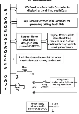
Fig 3.1.a:Block diagram of Programmable depth control drilling machine
The project work “Programmable drilling depth control machine” is mainly aimed to do the job of complicated drilling work at mechanical workshops. The procedure is described in this
Copyrights © International Journal of Intellectual Advancements and Research in Engineering Computations,
The main concept of this project work is to design & develop one special purpose-drilling machine, which can be used to drill the job with different depths programmed independently. These kinds of drill machines are very much required in the mechanical workshops, where it is essential for specific job applications. The machine is designed with a drilling motor, and the motor functions independently. Drilling depth of the motor can be programmed through the keyboard. The drilling motor is moved in vertical direction through power feed technology designed with stepper motor. The stepper motor used to move the drilling motor up & down directions is aimed to pull down the drill motor while drilling the hole over the job. Here some force is applied such that the machine can be able to drill the hole over light metal jobs. Since the project work is considered as prototype module, the stepper motor used here can apply a little force. To drill over heavy metals like MS, high power motor with suitable gear mechanism is essential.
The main purpose of this machine is to control the drilling depth accurately; therefore the control circuit should able to recognize the target entered through keyboard. In this regard, the vertical moving mechanism is coupled to the stepper motor shaft, as this motor rotates step wise & step angle is 1.8o, the movement of mechanism per step can be measured. Each pulse produced by the controller can rotate the motor by one step, since step angle is 1.8o, 200 pulses are required to rotate the motor for one full revolution. When the stepper motor completes one full revolution, initially movement in the vertical mechanism must be measured with the scale [7].
Based on this data the controller can be programmed through keyboard. For example, if the power feed motor (stepper motor) completes one revolution assume that the mechanism is moved by 1mm down, to move the mechanism by 1mm the controller has to produce 200 pulses. Now the controller can recognize the movement of mechanism by counting the pulses internally. The entire vertical moving mechanism that contains drilling motor is coupled with power feed motor can be called as depth control mechanism.
The depth control mechanism coupled to the drilling machine can be used for drilling to a desired depth; the desired depth can be programmed through a small keyboard interfaced
with controller chip. This technology prevents the twist drill from traveling too far after cutting through the work piece. The depth control mechanism was designed to be used whenever a number of holes of the same depth are to be drilled, or when drilling holes deep into the work piece. Make sure that drills are chucked tightly to avoid slipping and changing the depth setting. Most depth stops have away to measure the distance that the drill travels [5-6].
Some may have a fractional gage on the depth stop rod, and some may have a micrometer dial located on the depth stop for very precise measurements. But here in this concept depth control machine can be programmed such that no tool is required for measuring the depth. Once it is aligned, it can be used for mass production.
In general for checking the Depth of Drilled Holesaccurately, the length of the sides of the hole must be measured. Do not measure from the bottom point of the hole. A thin depth gage is inserted into the hole, along the side, and the measurement taken. If the hole is too small for the gage to fit down into it then a twist drill of the same size as the hole can be inserted into the hole upside down, then removed and measured with a rule. We must clean the holes before attempting any depth measurement. To avoid this pain full activity, this special purpose-drilling machine is designed.
Key board
The depth control mechanism is programmed through a small keyboard. This keyboard is designed with 12 keys & arranged as 3 X 4 matrix (3 rows X 4 columns) configuration: it is interfaced with microcontroller for entering the drilling depth data. The controller is programmed such that drilling motor movement can be controlled through this keyboard [8].
In addition to these 12 keys another key is also interfaced with controller & it is treated as reset key. During the drilling process for mass production, the machine functions continuously. Due to any reason if the operator wants to stop the machine, simply by pressing the Reset key, machine will be stopped automatically.
Mechanical transmission section
lubricated sliding channels, bearings, etc. The screw rod is directly coupled to the stepper motor shaft & its pitch is 2mm. When the controller generates 200 pulses, the stepper motor shaft completes one full revolution, there by the moving mechanism that holds the drilling motor will move for 2mm. If the motor rotates in forward direction, i.e., clock wise, the mechanism will be traveled towards down position, similarly if the motor rotates in anti-clock wise, the mechanism will be traveled towards up position.
The other end of the screw rod is coupled to the bearing. The bearing and motor both are firmly coupled to the mechanical structure. The mechanical structure that holds the drill motor is arranged over a metal stand. The moving mechanism is designed with two sliding channels, and the drilling motor is coupled with the sliding channels through brackets. As the stepper motor elevates the screw rod, the drilling motor & its mechanism will be moved along with the sliding channels. The screw rod can be called as elevating screw; this kind of mechanism that drives the drill motor can be called as programmable depth control Radial drilling machine. In idle condition the drilling motor remains at top level, at this position where motor is brought to a standstill can be said as home position. This home position is identified through limit switch [10].
Limit Switch
For identifying the home position & to restrict the vertical movement at top position, limit switch is arranged to the structure. This switch is interfaced with microcontroller as input signal. This limit switch is having long lever & when little pressure is applied to the lever, switch will be activated automatically.
The mechanical transmission section that carries the drill motor activates the switch at home position. Whenever the limit switch is activated, active low signal will be generated, based on this signal the microcontroller can recognize the position of drill motor.
Display section
The display section is designed to display the drilling depth data of the drilling motor. For this purpose an LCD panel is used & it is interfaced with microcontroller through its output port. This
display is having two rows & each row can display 16 characters. The drilling depth data of the motor is entered in mm through the keyboard, & is displayed in the LCD (Liquid Crystal Display) [9].
Stepper motor drive circuit
The stepper motor used in this project work can rotate its shaft by 1.8 degrees per step; means whenever the drive circuit receives a pulse from microcontroller chip, the motor shaft will be rotated by 1.8o. The drive circuit is designed with power Mosfet‟s & their drive transistors.
As the stepper motor is having 4 coils, the motor drive circuit is designed with 4 Mosfet‟s & 4 NPN low power-switching transistors. The mosfet & its driving transistor is configured as emitter following mode, based on the pulse produced by the controller the corresponding winding of stepper motor will be energized through its mosfet.
As the motor coils are supposed to be energized in a sequence, the pulses produced from the controller through four outputs can rotate the motor either in forward direction or in reverse direction. Since the maximum speed of the motor is 60 RPM, the controller chip is supposed to be producing 12000 pulses in one minute.
The motor requires 200 pulses to complete one full revolution, if 12000 pulses are produced in one minute, then the motor rotates at its maximum speed. Means the speed of the motor is depends up on the pulse rate produced by the controller, as the controller is programmed to produce pulses at fixed rate, motor speed remains as constant. If required speed can be adjusted through program, to do so again controller has to be re-programmed.
The output of the controller is used to drive the power Mosfet‟s through low power switching transistors; finally these power Mosfet‟s drives the stepper motor windings. The combination of transistor & mosfet provides the required current to energize the motor winding. As the controller is programmed to drive the motor in full step, it energizes any two windings simultaneously.
Stepper motor
Copyrights © International Journal of Intellectual Advancements and Research in Engineering Computations,
permanent Magnet (HYBRID) being the most popular now.
A variety of step angles are available, the most popular is the 1.8-degree per step or also referred as the 200 steps per revolution motor. The stepping action is achieved by switching the power to the Motor windings, so that the Motor phases are energized in a specific sequence. These motors have high holding torque when not being stepped, because current is being maintained on the motor winding.
The stepper motors operate on phase switched dc power. Basically two types of drives are used to operate stepper motors. In a bipolar drive, the direction of current flow through the winding will be controlled. In a uni-polar drive, the center tap of each winding is used and connected to the power source. Switching either end of winding to ground then controls the current flow.
When operated in this configuration, it is referred to as a four-phase motor. The stepper motors can be operated from very low speeds (0.01RPM) to high speeds (60 RPM) the performance of a stepper motor depends to a great extent on the control circuit used to drive the motor. Only with an appropriately designed control circuit, a stepper motor can be operated at rates up to 10,000 steps per second. In this project work unidirectional operation is considered.
The stepper motor is a form of synchronous motor, which is designed to rotate through a specific number of degrees for each electrical pulse received by its control unit. Stepper motors are built to follow signals as rapid as 1,200 pulses per second and with equivalent power ratings up to several kilowatts.A stepper motor is an incremental motion machine i.e. the motor, which turns in discrete movement (called the steps), is known as the stepper motor. Stepper motor does not rotate continuously, as a conventional motor does.
Microcontroller
The controller used here is belongs to 8051 family architecture & often it is referred to as MCS-51. This microcontroller is having an 8-bit data bus. In this family some of the controllers are capable of addressing 64K of program memory and a separate 64K of data memory. The 8051 has 4K of code memory implemented as on-chip Read Only Memory (ROM). The 8051 has 128 bytes of
internal Random Access Memory (RAM). The 8051 has two timer/counters, a serial port, 4 general purpose parallel input/output ports, and interrupt control logic with five sources of interrupts. Besides internal RAM, the 8051 has various Special Function Registers (SFR), which are the control and data registers for on-chip facilities. The SFRs also include the accumulator, the B register, and the Program Status Word (PSW), which contains the CPU flags. Programming the various internal hardware facilities of the 8051 is achieved by placing the appropriate control words into the corresponding SFR‟s.
As stated, the 8051 can address 64K of external data memory and 64K of external program memory. These may be separate blocks of memory, so that up to 128K of memory can be attached to the microcontroller.
Separate blocks of code and data memory are referred to as the Harvard architecture. The 8051 has two separate read signals, RD# and PSEN#. The first is activated when a byte is to be read from external data memory, the other, from external program memory. Both of these signals are so-called active low signals. That is, they are cleared to logic level 0 when activated. All external code is fetched from external program memory. In addition, bytes from external program memory may be read by special read instructions such as the MOVC instruction. There are separate instructions to read from external data memory, such as the MOVX instruction. That is, the instructions determine which block of memory is addressed, and the corresponding control signal, either RD# or PSEN# is activated during the memory read cycle. A single block of memory may be mapped to act as both data and program memory.
Drilling depth control circuit
This keyboard is designed to form a matrix of rows and columns. The micro-controller accesses both rows and columns through ports.
These 12 keys are arranged in 3x4 Matrix configurations, so that when a key is pressed, a row and a column make a contact. Otherwise, there is no connection between rows and columns.
The micro-controller (consisting of processor, RAM and EPROM, and three ports) takes care of hardware and software, when the keyboard is interfaced to it. In this concept, the micro-controller scans the keys continuously, i.e., the function of programs stored in the EPROM through the keys. The micro-controller monitors the keyboard continuously & detects the activated key automatically. Controller is programmed to store the data of activated keys information in to its EPROM.
The source of information is keyboard; the digital information produced by the keyboard is converted in to digital code. Here the micro-controller is playing a major role for converting the logic signals into digital codes. To detect a pressed key, the micro-controller makes high all rows by providing logic high at input, and then it reads the columns. If the data read from the columns all zeros, no key has been pressed and the process continues until a key press is detected.
When any key is pressed, the micro-controller detects and goes through the process of identifying the key. Starting with top row, the micro-controller reads all the columns. If the data read is all zeros, no key in that row is activated and the process is moved to next row.
This process continues until the row is identified. After identification of the row in which the key has been pressed, the next task is to find out which column the pressed key belongs to. This can be achieved, because the micro-controller knows at any time which row and column are being accessed.
All the rows are connected to one port of microcontroller and all the columns are connected to
another port of same microcontroller. The keyboard contains press to on type micro-switches having four pins and remains in normally open condition, when the key is pressed normally open contact gets closed to generate activated signal and this signal is fed to microcontroller. These switches are nothing but feather touch keys, popularly known as „button keys‟.
LCD panel
The LCD panel used for displaying the drilling depth data is interfaced with micro-controller through its output port. This is a 16 character x 2 Line LCD module, depending up on the length of data that is supposed to be displayed, suitable panel can be selected. Here 2 rows are enough for displaying the drilling machine drilling depth data. These panels are capable of display numbers, characters, and graphics. The display contains two internal byte-wide registers, one for commands (RS=0) and the second for characters to be displayed (RS=1). It also contains a user.
This LCD module used here contains 16 pins, as it accepts 8 bit data from controller, out of 16 pins 8 pins are data pins & these are interfaced with controller through its output port. The microcontroller used in this project work is having 32 I/O lines and 10 I/O lines are interfaced with LCD panel, D0 – D7 of LCD panel are called as 8 – bit data pins and this panel acquires the information from microcontroller through this data pins.
The enable (E) pin is used by the LCD to latch information presented to its data pins. When data is supplied to data pins, a high –to-low pulse must be applied to this pin in order for the LCD to latch in the data present at the data pins. This pulse must be a minimum of 450 ns wide. The 8-bit data pins, D0-D7, are used to send information to the LCD or read the contents of the LCD‟S internal registers.
Copyrights © International Journal of Intellectual Advancements and Research in Engineering Computations,
Fig; 3.2.a: Interfacing the display unit to the microcontroller
As seen from the above figure, Pins from 7 to 14 are data pins used for the selection of a particular character and pins 4 to 6 are Control signal pins used for performing Register bank selection, Read / Write and Enable pins
respectively. By adjusting the voltage at pin number 3 we can change the contrast of the display. To display a particular character or number its associated logic sequence has to be placed on the data pins and write signal (Pin-6) has to be enabled.
Microcontroller takes care of all these things based on the program loaded into it. All that we need to do is to depress the desired keys during the
logic sequence on the data pins based on the information obtained from the decoder output.
Stepper motor drive circuit
The motor used in this project work is having four windings; therefore the controller drives the motor through four outputs. The stepper motor windings are energized one after another in a sequence according to the code produced by the controller through motor drive circuit.
This motor rotates in step wise and the step angle is 1.80. Varying the pulse rate can vary the speed of the motor. The pulses are produced by the controller can be controlled through the program by which motor speed can be varied. The stepper motor used in this project work is capable to drive up to 5kg load.
To drive the stepper motor in both the directions (clockwise or anti-clockwise) the system is programmed to produce the pulses in a sequence at four different outputs, these sequential
programmed outputs energizes the motor windings one after another in a sequence. To drive the motor in clockwise, the sequence starts from top to bottom; similarly to drive the motor in anti-clockwise, the sequence starts from the bottom to top. Likewise the motor rotates in both the directions. The output of the controller is used to drive the power mosfets through switching transistors. These mosfets provide the required current to energize the motor windings. The stepper motor used in this project work is capable to drive up to 5Kg loads, i.e., the holding torque is 5Kg. When the winding is energized, each winding consumes 450 milli amps approximately. The advantage of using power mosfets is to minimize the switching losses; small low power NPN transistors are used to drive these mosfets. In general the current consumption of stepper motor is constant, irrespective of load weather it is applied or not.
Programmable Depth Control Drilling Machine
CONCLUSION
Drilling machines or drill presses are one of the most common machines found in the machine shops/mechanical workshops. A drill press is a
Copyrights © International Journal of Intellectual Advancements and Research in Engineering Computations,
operations performed on a drill press are drilling, reaming, tapping, counter boring, countersinking, and spot facing. These are quite common machines & available everywhere, but for specific applications we need special purpose drilling machines. Availability of these machines in our
country is critical; we may have to import them, for which we have to spend lot of amount. In this regard it is essential to develop special purpose drilling machines indigenously; therefore this project work is taken up.
This project revealed that building a relatively low cost, high precision drilling machine named as “Programmable drilling depth control machine” designed for workshops is aimed to offer benefits to the Industrialists. Since it is a prototype module, the system is designed with a single drilling motor; there by it can perform single operation at an
instant. To enhance the technology further & to make it more comfortable, drill motors can be increased such that a particular specific task can be achieved with the single machine, therefore it can be used for more applications.
To prove the concept practically, a prototype module is constructed for the live demonstration, & results are found to be satisfactory.
REFERENCES
[1]. Mechatronics and Measurement Systems
[2]. By: David g. Alciatore, Michael B. Histand Mechatronics –Electronic Control Systems in Mechanical and electrical Engineering –By: W. Bolton
[3]. Introduction to Robotics By Saeed B. Niku
[4]. The 8051 Micro-controller Architecture, programming & Applications By: Kenneth J. Ayala [5]. Mechanism and Machine Theory By: J.S. Rao, R.V. Dukkipati
[6]. Practical transistor circuit design and analysis By: GERALD E. WILLIAMS
[7]. Robotic Engineering An Integrated Approach By: Richard D. Klafter, Thomas A. Chmiclewski, and Michael Negin
[8]. Programming and Customizing the 8051 Micro-controller By: Myke Predko [9]. The concepts and Features of Micro-controllers - By: Raj Kamal