Rhombus Shaped Reconfigurable Microstrip Antenna for wireless
Applications
Madhusudhana K1, Dr S Jagadeesha2
1,2
Department of Electronics & Communication Engineering, SDMIT, Ujire, Mangalore, India
Abstract—Rhombus Shaped Reconfigurable microstrip antenna is designed to operate at lower frequency i.e 1.74GHz. The Designed antenna increase Bandwidth as well reduction in size. Comparative analysis has made with reference to without and with capacitor as a lumped element. Design analysis and Simulation is carried out by using IE3D software and practical results are measured by Vector Network analyzer. The size reduction of Rhombus shaped Reconfigurable microstrip antenna gives best possible size reduction of 75.95% with overall bandwidth 86MHz.
Keywords—Reconfigurable microstrip antenna, wireless application, multiple frequencies
I. INTRODUCTION
Microstrip antennas [1] are the most rapidly developing field in the last twenty years. Currently these antennas have a large application in mobile radio systems, integrated antennas, satellite navigation receivers, satellite communications, direct broadcast radio and television, etc. The considerable interest in microstrip antennas is due to their advantages compared to conventional microwave antennas as a light weight, low volume, conformability, and ease of manufacture. One of the most serious disadvantages of microstrip antennas is their limited bandwidth.
Microstrip antenna (MSA) [2] has several advantages compared to the conventional microwave antennas. Some of advantages of Microstrip antennas discussed by [3] are listed as follows:
• Light weight and low volume.
• Low profile planar configuration which can be easily made conformal to host surface. • Low fabrication cost, hence can be manufactured in large quantities.
• Supports both, linear as well as circular polarization.
• Can be easily integrated with microwave integrated circuits (MICs). • Capable of dual and triple frequency operations.
• Mechanically robust when mounted on rigid surfaces.
However Microstrip antenna (MSAs) suffer from many disadvantages compared to conventional antennas. Some of them are as follows:
• Narrow bandwidth
• Quite large size for lower microwave frequencies • Low efficiency
• Low Gain
• Extraneous radiation from feeds and junctions • Poor end fire radiator except tapered slot antennas • Low power handling capacity
W L
W
Lt
Lf
International Journal of Modern Trends in Engineering and Research (IJMTER)
Volume 02, Issue 12, [December – 2015] ISSN (Online):2349–9745 ; ISSN (Print):2393-8161
However, there are ways of substantially diminishing the effects of these disadvantages. The techniques to overcome the first two limitations are discussed extensively in this paper. The limitation of MSA can overcome by using a Reconfigurable concept with microstrip antenna.
Reconfigurable antenna has a significant Potential in the modern wireless communication. This is as a result of the reduction in antenna size and cost, and convenience for certain applications to operate with a single antenna than multiple Antennas [5].Moreover, these reconfigurable antennas have interesting characteristics as they can provide various features in different operating frequencies [6]-[7], polarizations [8], [9], and radiation patterns [10], [11] by changing the current distribution over the volume of the antennas.
II. ANTENNA DESIGN
Rhombus shaped Microstrip patch antenna are designed with three essential parameters are: i) Frequency of operation (f0): The resonant frequency of the antenna must be selected appropriately
which is able to operate under desired frequency range. The frequency of operation in this design is 1.8GHz.
ii) Dielectric constant of the substrate (εr): The dielectric material selected for design is glass epoxy
which has a dielectric constant 4.4.
iii) Height of dielectric substrate (h): For the Microstrip patch antenna to be used in cellular phones, it is connected that the antenna should not be bulky. Hence, the height of the dielectric substrate is selected as 1.6mm.
Design of Microstrip line feeding:
λo = where f is the resonating frequency
Width of patch W= ( ; Effective length ( ( )
( ( ),
Where = ; Length of Patch
√ 2
Let Zo=50 =4.4 ; = for < 2,
Where A= √( + (0.23 + ) ;
= [ B – 1 – ln(2B – 1) + { ln(B – 1) + 0.39 }] for > 2, Where B=
√ ;
Let us assume w/d < 2
Rin =
( (
√
( ; where l=( ( β = √ ;
=√ ;
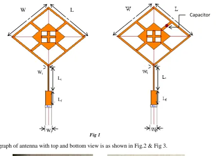
The optimized geometry of proposed rhombic Microstrip antenna is as shown in Fig.1 The Rhombus shaped microstrip antenna whose size is of 41mm x 41mm is printed on a dielectric substrate of thickness 1.6mm. The material used in glass epoxy with dielectric permittivity of εr=4.4 which is
designed to operate at 1.8GHz.This antenna is fed by microstrip line of dimension (Lf50,Wf50)=15mm,4.84mm through quarter wave transformer having (Lt50,Wt50)=24.05mm,
International Journal of Modern Trends in Engineering and Research (IJMTER)
Volume 02, Issue 12, [December – 2015] ISSN (Online):2349–9745 ; ISSN (Print):2393-8161
iteration, this curve begins as a straight line imposed upon the sides of the square. Next,another square of side length each side of the square is removed. The antenna are initially simulated using IE3D software and all the parameters are optimized and they are as follows:
h=1.6mm, L=41.08mm, W=41.08mm, Ls=10.27mm, Ws=10.27mm, Lt=24.05mm, Wt=0.72mm,
Lf=15mm, Wf=4.84mm.
Fig 1
Photograph of antenna with top and bottom view is as shown in Fig.2 & Fig 3.
Fig 2 Front and back view of Rhombus shaped Microstrip antenna without capacitor
Fig 3 Front and back view of Rhombus shaped Reconfigurable Microstrip antenna with capacitor
W L
Wt
Lt
Lf
Wf
International Journal of Modern Trends in Engineering and Research (IJMTER)
Volume 02, Issue 12, [December – 2015] ISSN (Online):2349–9745 ; ISSN (Print):2393-8161
III. RESULT AND DISCUSSION
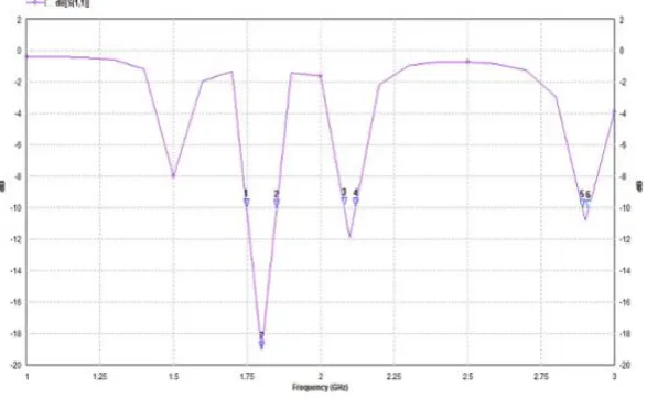
Simulation & Practical Results: Fig 4 & Fig 6 shows the simulated Return loss of Rhombus shaped Microstrip antenna without and with Capacitor & Fig 5 & Fig 7 shows the practical Return loss of Rhombus shaped Microstrip antenna without and with Capacitor
Fig 4 Return loss of Rhombus shaped Microstrip antenna without Capacitor
Fig 5 Practical return loss of Rhombus shaped Microstrip antenna
International Journal of Modern Trends in Engineering and Research (IJMTER)
Volume 02, Issue 12, [December – 2015] ISSN (Online):2349–9745 ; ISSN (Print):2393-8161
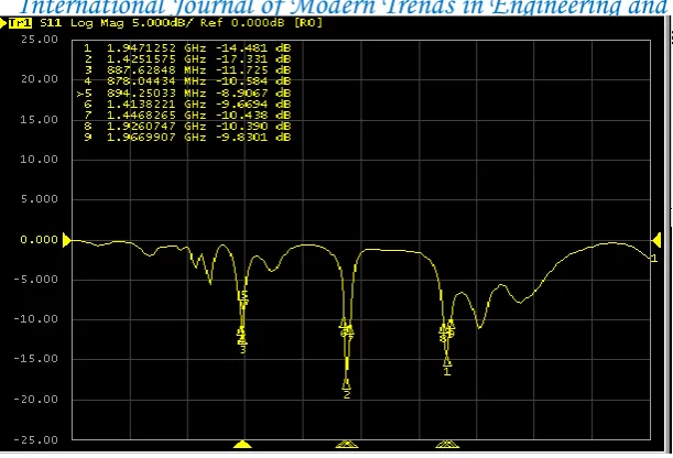
Fig 7 Practical return loss of Rhombus shaped Reconfigurable Microstrip antenna with capacitor
Fig 8 Radiation characterization
Sl No
Prototype Antenna
Resonant frequency fr(GHz)
Return loss (db) Bandwidth (MHz)
Over all Bandwidth (MHz)
Sim Pract Sim Pract Sim Pract Sim Pract
1
Structured Antenna without Capacitor
1.8 1.81 -13.1 -18 60 20
66 20
2.154 2.8 -11.8 -10 6 0
2
Structured Antenna with Capacitor
1.8 0.89 -11 -11 30 16
160 86 2.09 1.42 -12 -17.33 40 30
2.89 1.94 -19 -14.48 90 40
Table 1: Results of the proposed antenna
International Journal of Modern Trends in Engineering and Research (IJMTER)
Volume 02, Issue 12, [December – 2015] ISSN (Online):2349–9745 ; ISSN (Print):2393-8161
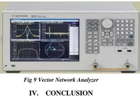
Fig 9 Vector Network Analyzer
IV. CONCLUSION
Rhombus Shaped Reconfigurable microstrip antenna gives a best size reduction of 75.95% with reference to without and with capacitor as a lumped element and its equivalent bandwidth obtained are 20MHz and 86MHz respectively.
REFERENCES
[1] H. Wang, X. B. Huang, D. G. Fang, and G. B. Han,” A Microstrip Antenna Array Formed by Microstrip LineFed Tooth-Like-Slot Patches”,“IEEE TRANSACTIONS ON ANTENNAS AND PROPAGATION, VOL. 55, NO. 4, APRIL 2 7”
[2] K. F. Lee, Ed,” Advances in Microstrip and Printed Antennas”,” John Wiley, 1997” [3] F. E. Gardiol, “Broadband Patch Antennas,” Artech House
[4] Preet Kaur,Ed,” Design of a Novel Reconfigurable antenna for multiband application”, “International journal of advanced science and technology, Vol.62,(2014),pp.103-112”
[5] N. Ramli,Ed,” Design of an Aperture-Coupled Frequency Reconfigurable Microstrip Stacked Array Antenna for LTE and WiMAX Applications”.
[6] B. A. Cetiner, G. R. Crusats, L. Jofre, Biyikli, and Necmi, “RF MEMS Integrated Frequency Reconfigurable Annular Slot Antenna,” IEEE Transactions on Antennas and Propagation, vol. 58, no. 3, pp. 626-632, March 2010. [7] S. Muhamud - Kayat, M. T. Ali, M. K. Mohd Salleh, M. H. Mohd Rusli, N. Ramli, and H. Alias, “Truncated
Rhombus-Like Slotted Antennas with Aperture Coupling Technique,” Progress In Electromagnetics Research Letters, Vol. 39, 181-198, 2013.
[8] J. Perruisseau-Carrier, “Dual-Polarized and Polarization-Flexible Reflective Cells With Dynamic Phase Control,” IEEE Transactions on Antennas and Propagation, vol. 58, no. 5, pp.1494-1502, May 2010.
[9] F. Ferrero, Ed, "A Novel Quad-Polarization Agile Patch Antenna,” IEEE Transactions on Antennas and Propagation, vol. 57, no. 5, pp.1563- 1567, May 2009.
[10] D Rodrigo, J. Romeu, S. Capdevila, and L. Jofre, “A Figure-of-Merit for Pattern Reconfigurable Antennas,” IEEE Transactions on Antennas and Propagation, vol. 61, no .3, pp.1448-1453, March 2013.