Procedia Computer Science 55 ( 2015 ) 876 – 885
1877-0509 © 2015 Published by Elsevier B.V. This is an open access article under the CC BY-NC-ND license (http://creativecommons.org/licenses/by-nc-nd/4.0/).
Peer-review under responsibility of the Organizing Committee of ITQM 2015 doi: 10.1016/j.procs.2015.07.147
ScienceDirect
Information Technology and Quantitative Management (ITQM 2015)
Design and Development of FPGA-based High-Performance
Radar Data Stream Mining System
Ying Liu
a,b,*, Pengshan Ma
a, Hongyuan Cui
aaSchool of Computer and Control, University of Chinese Academy of Sciences, Beijing 101408, China bKey Lab of Big Data Mining and Knowledge Management, Chinese Academy of Sciences, Beijing 100190, China Abstract
Radar signal sorting is a key technique in electronic reconnaissance systems and is currently an important research direction in radar signal processing. Clustering, one of data mining techniques, has been adopted to solve radar sorting problem. However, none of the existing clustering-based methods is able to perform real-time analysis on high speed radar stream. Therefore, in this paper, we propose, design and implement a high performance FPGA-based data stream mining system to perform real-time radar signal sorting on continuous data stream. Firstly, a density-based clustering algorithm is proposed for radar signal sorting; secondly, FPGA-based program of the clustering algorithm is designed and implemented; thirdly, the FPGA board is designed and implemented. Experiments are performed on the board we designed. The results show that the proposed system can achieve real-time radar signal sorting on FPGA, and the resource consumption on FPGA is very low. The clustering algorithm is efficient in terms of accuracy.
© 2015 The Authors. Published by Elsevier B.V.
Selection and/or peer-review under responsibility of the organizers of ITQM 2015 Keywords: data mining, clustering, signal processing, FPGA, parallel computing
1. Introduction
Radar, shorted for radio detection and ranging, is a device that finds the target with a radio method or electromagnetic wave and measures its spatial location. By transmitting electromagnetic waves irradiated from the target and receiving an echo, Radar can obtain the distance to the target, the velocity, elevation of the target and other information. The advantages of radar is that it is able to detect distant targets all day and all night, immune to fog, clouds and rain. In addition, it is able to penetrate. Therefore, it is not only used in military electronic equipment, but also widely used in social and economic development, such as weather forecasting, resource exploration, environmental monitoring, celestial studies, atmospheric physics, etc.
*Corresponding Author
E-mail address: [email protected]
© 2015 Published by Elsevier B.V. This is an open access article under the CC BY-NC-ND license (http://creativecommons.org/licenses/by-nc-nd/4.0/).
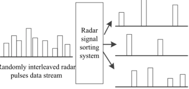
Radar signal is randomly interleaved in transmission, as shown in Figure 1. So, it is an important prerequisite for radar signal processing to separate different signals out of a mixed sequence. The process that separates the randomly interleaved signals into separate signal sequences is called radar signal sorting.Signal sorting is a key technique in electronic reconnaissance systems and is currently an important research direction in radar signal processing. Modern radar surveillance equipment working in high-density signal environmental must have signal sorting function. Traditional radar sorting methods include histogram analysis, sequence search method, hardware-based methods, etc.
Data mining is a technique that extracts implicit and valuable knowledge from a massive, noisy data set. In the past ten years, data mining has been used in various areas such as commercial, scientific, and military. For example, Sun at al. [5] proposed an improved K-means algorithm for radar signal sorting. It automatically determines the number of clusters, cluster centres and may be able to adapt to unknown radar signal sorting effectively.
Radar signal sorting system Randomly interleaved radar
pulses data stream
Figure 1 The process of radar signal sorting
Although the existing data mining-based radar sorting methods have obtained good results in some tests, they are not able to meet the needs of practical applications because the radar signal is a data stream, which has a very high rate, quick changes, serious noise, especially in a complex electromagnetic environments in battlefields. Researchers have proposed and implemented some stream mining algorithms, for example, Han et al. [2] proposed a dynamic data stream classification algorithm where the stream is divided into data chunks by tilting time windows. Each data stream sheet is described by statistic value (micro-cluster), and is modelled based on micro-cluster. It can adapt to dynamic changes in the data stream quickly and update model immediately. However, researches on sorting algorithms for radar data stream have not been seen yet. On the other hand, as the rate of radar signal stream is high (up to several millions of signals per second), CPU-based sorting algorithm is difficult to meet the performance requirements of real-time applications.
Therefore, in this paper, in order to achieve real-time radar data stream sorting, we conduct our research on high performance radar stream sorting from the following aspects: 1) Propose a self-adaptive clustering algorithm for radar signal sorting; 2) Design and implement a parallel signal sorting algorithm on FPGA; 3) Design and implement a corresponding FPGA board. A simulation is performed to evaluate the performance of our proposed system. The accuracy of the clustering algorithm is high. The results show that the proposed system can achieve real-time radar signal sorting on FPGA, and the resource consumption on FPGA is less than 2%. The delay of the algorithm is about 3.35s for with clock frequency 500MHz.
This rest of paper is organized as follows: Section 2 briefly introduced some related work; Section 3 presents a self-adaptive clustering algorithm we proposed for radar signal sorting; Section 4 introduces FPGA and development tools; Section 5 presents the details of the design and implementation of FPGA-based radar signal sorting and the experimental results; Section 6 presents the design of our FPGA board; Our work is summarized in Section 7.
2. Related work
In recent years, some researchers have explored to apply data mining methods for radar signal sorting. Currently, clustering algorithms have been used and achieved some fruits. Wang et al. [3] proposed a fuzzy
clustering method, which uses a new fuzzy clustering algorithm-tracing method. The weakness is that the algorithm can only run on a single, not suitable for real-time data processing. Guo. [4] used support vectors in clustering. But, since it incurs a huge amount of calculation and high computational complexity, it fails in real-time data mining. Sun. [5] proposed an improved K-means algorithm for radar signal sorting which automatically determines the number of clusters, cluster centres and may be able to adapt to unknown radar signal sorting. However, it does not provide whether it is valid in real-time applications.
3. Self-adaptive clustering algorithm
3.1 Comparisons of algorithms
Clustering is a technique that automatically aggregates objects into different groups, where objects in the same group are similar to each other, but objects in different group are dissimilar. The number of clusters is unknown in advance. Clustering methods include partitioning methods, hierarchical methods, density-based methods, grid-based methods, etc. A fundamental difference between density-based methods and other methods is that it is not based on distance but based on density which allows them to overcome the shortcomings of distance-based clustering algorithm which can only find ‘quasi-circular’-shaped clusters.
In K-means algorithm, K (the number of clusters) is not known in advance but has to be pre-determined by the users based on empirical experience. Next, the distribution of the cluster centres is randomly selected at the beginning and then is optimized gradually. The distribution of the initial cluster centres has does affect the quality of the clustering result. In addition, when data size is huge, the computation cost will be very high. So K-means algorithm is not suitable for unknown radar signal sorting.
Therefore, we propose a density-based self-adaptive clustering algorithm for unknown radar signal sorting.
3.2 Self-Adaptive clustering algorithm
A. Terminology
Assume Npoints are to be clustered in the space and the values of each dimension have already been normalized into [0, 1]. Let us start with the definitions of a set of new terms.
z k-dist: The distance between a point and its kth-nearest neighbour [8].
z Uniformity:It indicates the data follows uniform distribution to some degree. We define the deviation of the standard deviation of the sample from that of uniform distribution as the uniformity, as shown in Equation (3-1). As each point in the data is described by multiple attributes/dimensions, the ‘worst’ uniformity is selected as uniformity.
` _ _ ^PD[ L G X X X X L L L E D E J
Įi(u): the standard deviation of the sample in dimensioni;
ȕi(u): the standard deviation of uniform distribution in dimensioni;
Ȗ(u): the uniformity of the data.
z Core Object:To be called a core object, a point has to satisfy two criteria: 1) the number of points in its İ -neighbourhoodis greater than MinPts; 2) its uniformity is greater than Ȝ İ-neighbourhood andMinPtsare density related thresholds whose determination method will be provided in the next subsection, which is the highlight of the proposed clustering algorithm.
B. Parameter Determination Method
For each point pi, calculate its distance to all the other points, and record the distance to its kth-nearest
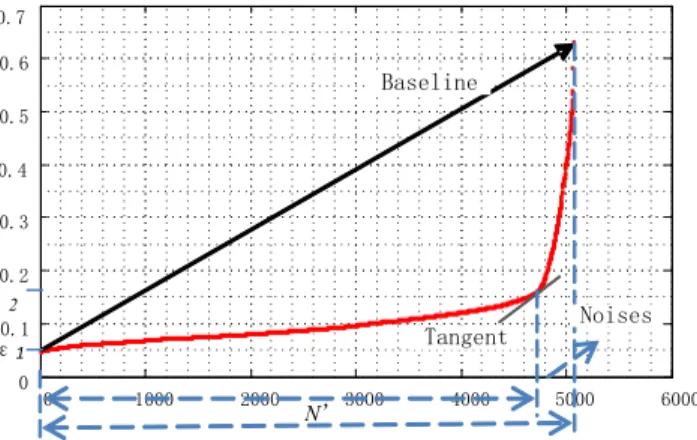
neighbour as k-disti. Then, sort k-disti(i=1,…, N) in a increasing order. For example, all the k-distiare plotted in
red in Figure 2, where the x-axis denotes the accumulated number of points and the y-axis denotes the value of k-dist. We can see that the scatterplot in red rises slowly at the beginning and we mark the lowest value on y -axis as İ1. %DVHOLQH
Nÿ 7DQJHQW
1RLVHV ¦2 ¦1
Figure 2 Scatterplot of the points sorted in increasing order of k-dist
In Figure 2, the scatterplot in red rises sharply at the end part, where the points falling in this part are viewed as noises. Let’s call the line connecting the first point and the last point as baseline, and the slope of
baselineas base-slope, as illustrated in Figure 2. The method to locate noises is as follows: 1) Calculate the tangent of each point on the scatterplot;
2) For each point, check its tangent. Whenever a tangent goes beyond base-slope, we mark the corresponding k-dist as İ2. The points whose tangents greater than base-slopeare defined as noises.
Assume that the total number of non-noise points is N’.In this paper, MinPts is defined asratio factor´N’, where ratio factorcould be 1/40, 1/20, etc. İ-neighbourhoodis defined as the third quartile of İ1and İ2. In this
way, the values of MinPtsand İ-neighbourhoodare adaptive to the distribution of the data itself, rather than specified by users empirically as global constant parameters.
In real radar signal sorting applications, the density of the pulses (points) from different emitters may vary significantly. In such case, the corresponding scatterplot of the points sorted in the increasing order of k-dist looks like line Bin Figure 3, which steps up like stairs. Our algorithm will calculate distinct İ-neighbourhood -for each segment respectively, as well as MinPts.
f e d c b a B A
Figure 3 Scatterplot of the points in different cases. Line A indicates only one density threshold will be generated for data set A, but multiple density thresholds for data set B.
Once the significant input parameters are obtained, we start to grow clusters. In order to be defined as a
FOXVWHUWKHUHJLRQPXVWVDWLVI\WZRFULWHULDWKHXQLIRUPLW\RIHDFKSRLQWLVJUHDWHUWKDQȜDXVHUVSHFLILHG
parameter indicating how much it follows uniform distribution; 2) each point falls in İ-neighbourhood of another point in a given cluster. A cluster is a maximal set, where the points are distributed uniform enough and no more point falls in İ-neighbourhood of any existing member. The pseudo code is presented in Figure 4.
Input:k, data set D,Ȝ
Output: clustetrs
1) for each point pinD
2) calculatek-dist; 3) sort all the k-dist; 4) for each point pinD
5) calculate its slope;
6) find noises, calculateMinPtsand¦-neighborhood; 7) for each point pinD
8) if |points|>=MinPts&&¤(p)>=¬ 9) markpas a core object; 10) for each core object i
11) for each core object j(i!=j)
12) if(j!=null)&& (i!=null) &&(jis in ¦ -neighborhoodofi)
13) mergejtoi;j=null;
Figure 4 Pseudo code of the self-adaptive clustering algorithm
From line 1 to line 6, we scan the data and calculate MinPts and İ-neighbourhood.Line 7-9 finds all the
core objects. Line 10-13 discovers all clusters satisfying both the density criteria and the uniformity criteria. It is evident that the complexity of this algorithm is O(N2), the same as that of DBSCAN [9] which is one
of the best density-based clustering methods. But, as the uniformity threshold filters out the points that are not distributed uniform enough, its computation is less than that of DBSCAN.
4. FPGA and Vivado HLS
4.1 FPGA and its strengths
FPGA (Field-Programmable Gate Array) is a device that its logic function is determined by Hardware Description Language (HDL). It belongs to semi-customized integrated circuits and thus both solves the problem of custom circuits and overcomes the disadvantages original programmable devices have that a limited number of gates. Because of its high scalability, re-configurability and capability for real-time processing, FPGA has been widely used in communications, radar signal processing, image video processing, electronic warfare, aerospace, industrial control, etc. Due to its rapid development in recent years, FPGA has strong parallel computing capabilities. FPGA is a good candidate for real-time radar data analysis in battlefields.In addition, FPGA board can be configured with different functions by using different HDL code, which greatly reduces the difficulties and cost in development. Therefore, we use FPGA to implement our self-adaptive clustering algorithm.
4.2 Vivado HLS
achieve an RTL-level hardware function by writing C/C++ or other high-level language, namely, it can convert C/C++ code to HDL code. For a complex algorithm design, it is time-consuming, inefficient and needs long simulation time to use traditional hardware description language (VHDL or Verilog HDL). So, we use Vivado HLS tool to convert C/C ++ code.
5. FPGA-based self-adaptive clustering algorithm
5.1 Hardware environment
1. Hardware platform: 2GB DDR3, Intel (R) P6000 CPU 1.87GHz. 2. Software: Windows 7, 32-bit, Visual Studio 2008, Vivado HLS 2012.4
3. Our proposed clustering algorithm is implemented in C/C++ in Visual Studio 2008 and Vivado HLS 2012.4 separately.
4. Test data: 5,000 pulses data points are used as the source data. This set of data will be repeated many times to simulate a radar signal stream.
5.2 Synthetic code by Vivado HLS
In both CPU code and Vivado HLS environment, a data structure structis defined to represent a data point in source data. There are totally 5,000 points. Struct, named as data_set_t consists of four attributes: carrier frequency, angle of arrival, pulse width and other information, as shown in Figure 5.
struct data_set_t {
float data [3] [5000];
unsigned char visited [5000]; };
Figure 5 Data structure used in Vivado HLS
The syntax of the C/C++ language is not fully supported in Vivado HLS. Since there is no way to know the number of radar sources in advance, in the CPU code, the algorithm uses alink list(or vector)to store the points in each cluster. Whenever a new cluster is identified, a cluster will be appended at the end of the link list.
In Vivado HLS, variable-length array, variable-length pointers or variable-length vector has not been supported yet. It means that the number of points in each cluster has to be known in advance and predefined which is actually not possible to know due to the nature of the problem. Therefore, we solve the problem by using a maximum number of radar sources and using a variable to indicate the actual number. For example, there are actually six radars eventually, but we set the maximum number at 100 to allow sufficient memory space. Similarly, in each cluster, the maximum number of data points is set at the total number of points.
We debug the self-adaptive clustering algorithm in accordance with the requirements in Vivado HLS to a synthetic C/C++ code and then the C/C++ code can be translated into HDL.
5.3 Experimental Results
Six clusters are discovered from 5,000 pulse sample points by our proposed self-adaptive clustering algorithm. The sorting leaking rate is 0.77% (36 points are leaked); the sorting error rate is 0.98% (46 points are placed into the wrong cluster).
The results of the synthetic code from Vivado HLS obtained the same results as the CPU code. It means that the conversion from C/C++ to HDL code is correct.
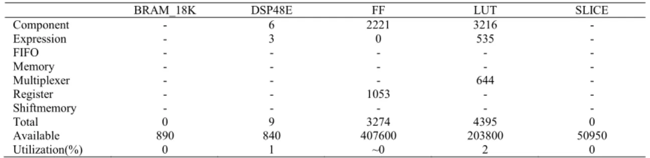
Table 1 Resource utilization of FPGA code
BRAM_18K DSP48E FF LUT SLICE
Component - 6 2221 3216 -Expression - 3 0 535 -FIFO - - - - -Memory - - - - -Multiplexer - - - 644 -Register - - 1053 - -Shiftmemory - - - - -Total 0 9 3274 4395 0 Available 890 840 407600 203800 50950 Utilization(%) 0 1 ~0 2 0
Since the utilization rate of BRAM_18K is 0 in Table 1, no data is stored in the chip's internal BRAM, but in the external RAM. The numbers in DSP48E indicate the algorithm has used multipliers. FF (flip-flop) is the basic storage unit. LUT is the lookup table which outputs a value according to the input. Slice is part of the configurable logic block (CLB) components. Overall speaking, the FPGA resources used by the self-adaptive clustering algorithm are 0% -2% of the total resources. The delay is about 3.35s (1,675,010,000 clock cycles), when the clock frequency is 500MHz.
In order to evaluate the performance of our proposed algorithm on radar stream, we simulate a radar stream by repeating the 5000 pulses continuously. Constant delay is achieved and maintained at 3.35s. It is evident to see that our FPGA-based implementation has a high efficiency and can be adapted to real-time radar signal sorting task.
6. FPGA board design
6.1 PXI Express
PXI (PCI eXtensions for Instrumentation) industry standard has gained rapidly development and been widely used in the field of automatic test systems since its release in 1998. The key factor that this standard was promoted to be adopt rapidly is that it used the PCI technology in communication backplane. Now, as PCI bus in the commercial PC industry was upgraded to PCI Express bus, the available bus bandwidth was significantly increased. So, National Instruments (NI) released PXI Express (PCI EXPRESS eXtensions for Instrumentation) bus architecture in 2005.
The FPGA board complies with PXI Express bus specification. Due to its large bandwidth, greater than 40Gbps, it has strong scalability and flexibility. In the field of high-speed data transmission and processing the SMA, SSMB or similar high-speed interfaces are commonly used. Its architecture allows the replacement of boards with different functions or interfaces.
6.2 FPGA board design
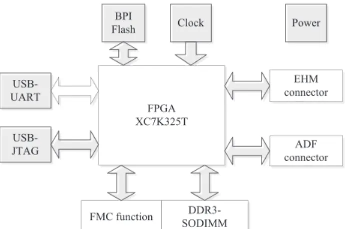
EHM connector FPGA XC7K325T FMC function ADF connector DDR3-SODIMM BPI Flash Clock USB-UART USB-JTAG Power
Figure 6 FPGA board architecture for radar stream mining
Data transfers between PXI Express backplane and the FPGA board by ADF and EHM connector. PXI Express architecture is shown in Figure 7. CPU, GPU, FPGA or any other card can be plugged into the bus simultaneously. FPGA PXI Express Bus Forming PDW ADC FPGA sorting Ext. FPGA DAC Amplifier Filter CPU GPU
Figure 7. PXI Express architecture
Our FPGA board consists of the following circuits: configuration circuit, FMC circuit, DDR3 circuit, USB to JTAG circuits, USB to UART circuits, backplane circuit and power circuit. Among them:
1) Configuration circuit: used to load programs stored in a BPI FLASH chip when power on.
2) FMC circuit: used as extension, input or output. It can be connected to any of the daughter-card complying with FMC protocol.
3) DDR3 SDRAM: used to store data temporarily. 4) USB circuit: used to communicate with PC.
5) Backplane circuit: used to exchange data via the connector.
6) Power circuit is used to supply power to all the components on the board.
The core chip is XC7K325T-2FFG900I which belongs to Xilinx's Kintex-7 series chips. Its design is as follows:
debugging of FPGA need to use JTAG. A USB cable is used to complete the configuration by putting USB-to-JTAG bridge chip, which greatly facilitates debugging.
2) There are eight PCI Express 2.0 channels in the backplane connector interface and the bandwidth of each channel is up to 5.0Gbps. The total bandwidth will be greater than 40Gbps if the control signals are considered.
3) DDR3 SO-DIMM complies with JESD79-3F and 204-Pin DDR3 SDRAM Unbuffered SO-DIMM Design Specification. It supported up to 8GB, 1600Mbps.
4) FMC circuit complies with ANSI/VITA 57.1-2008 standard. All pins in bank A and bank B are supported, including 34 differential pairs in LA, 24 in HA and 22 in bank B. FMC supports 8-channel high-speed serial GTX transceivers. By designing different FMC daughter card, we can achieve a variety of extensions such as sampling system, playback system. The voltage VADJ is considered. FPGA's bank 16, 17, 18 is used as FMC's bank A and thus the I/O power part of FPGA is separate and adjustable from 0.6V to 3.3V. It enhances the compatibility of the board.
5) UART (Universal Asynchronous Receiver/Transmitter) is a general term that includes RS232, RS485, etc. Its function is to complete conversion of the parallel data to the serial. These chips are usually integrated in the communication interface. We use Silicon Labs Inc.’s USB-UART bridge chip CP2103 to facilitate the realization of the communication between PC and FPGA.
7. Summary
Radar is an important technique in military, aviation, aerospace, remote sensing. Various clustering methods have been adapted to solve the radar signal sorting problem. However, as the existing radar sorting methods are not able to process high speed data stream continuously, they are not able to meet the requirement of radar signal sorting applications. Therefore, in this paper, we proposed a FPGA-based high performance data stream mining system for real-time radar signal stream sorting. The contribution can be summarized in three points: 1) A self-adaptive clustering algorithm is proposed for radar signal sorting; 2) A parallel signal sorting algorithm on FPGA is designed and implemented; 3) The corresponding FPGA board is designed and implemented. The experimental results on simulated radar stream showed that our proposed system can achieve real-time radar signal sorting on FPGA, and the resource consumption on FPGA is less than 2%. In addition, the accuracy of the proposed clustering algorithm is high.
Acknowledgements
This project is partially supported by grants from Natural Science Foundation of China #61202321/70621001/70921061.
Reference
[1] Guo Q. Theory Researches for Radar Signal Sorting [M]. Beijing: Science Press, 2010: 1-66
[2] Han JW, Micheline Kamber. Data Mining Concepts and Techniques [M]. USA: Academic Press, 2001: 363-374 [3] Wang Yonggang. radar signal sorting method based on fuzzy clustering, the PLA Electronic Engineering Institute,
Hefei 230037, electronic countermeasures, 2007.2
[4] Guo Q. Support Vector Clustering and Type-Entropy Based Joint De-interleaving/recognize System of Radar Pulse Sequence. ICIC 2006: 642-653
[5] Xin Sun, Huiqun Hou, Chengzhi Yang. An unknown radar signal Sorting method based on improved K-means [J]. Modern Electronic Technology. 2010
[6] Yang QˈWang JT. A Sorting Algorithm Based on Adaptive Density Threshold for Unknown Radar Signals [J]. Electronic Information Warfare Technology, 2012, 27(1): 16-19
[7] NI. PXI Express Specification Tutorial [EB/OL]. Http://www.ni.com/tutorial/2876/zhs/, 2015-2-12
School of the Academy of Science, 2009, 26(4): 530-538
[9] Martin Ester, Hans-Peter Kriegel, Xiaowei Xu. A Density-Based Algorithm for Discovering Clusters in Large Spatial Databases with Noise. KDD 1996: 216-221
[10] Zhan LˈTang AH. A Radar Signal Sorting Approach Based on Multi-dimensional and Weighted Clustering [J]. Journal of Telemetry, Tracking and Command, 2007, 28(Suppl): 113-117
[11] H.E.hassan. a New Algorithm for Radar Emitter Recognition. Proceedings of the 3rd International Symposium on Image and Signal Proceeding and Analysis 2003: 1097-1101
[12] Wang JG, Jin XM. Survey on De-interleaving Technique for Modern Radar Signal [J]. Radar Science and Technology, 2006, 4(2): 105-108
[13] Zhang WJ, Fan FH. Application of Cluster Method to Radar Signal Sorting[J]. Radar Science and Technology, 2004, 2(4): 219-223