HAL Id: hal-02467876
https://hal.archives-ouvertes.fr/hal-02467876
Submitted on 5 Feb 2020
HAL
is a multi-disciplinary open access
archive for the deposit and dissemination of
sci-entific research documents, whether they are
pub-lished or not. The documents may come from
teaching and research institutions in France or
abroad, or from public or private research centers.
L’archive ouverte pluridisciplinaire
HAL
, est
destinée au dépôt et à la diffusion de documents
scientifiques de niveau recherche, publiés ou non,
émanant des établissements d’enseignement et de
recherche français ou étrangers, des laboratoires
publics ou privés.
An Example of a Pitfall in Aerodynamic Shape
Optimization
Daniel Destarac, Gérald Carrier, George R. Anderson, Siva Nadarajah, Daniel
J. Poole, John C. Vassberg, David W. Zingg
To cite this version:
Daniel Destarac, Gérald Carrier, George R. Anderson, Siva Nadarajah, Daniel J. Poole, et al.. An
Example of a Pitfall in Aerodynamic Shape Optimization. AIAA Journal, American Institute of
Aeronautics and Astronautics, 2018, 56 (4), pp.1532-1540. �hal-02467876�
An Example of a Pitfall
in Aerodynamic Shape Optimization
Daniel Destarac*and Gérald Carrier†ONERA, F92190 Meudon
George R. Anderson‡
Science and Technology Corp., Moffett Field, CA 94035
Siva Nadarajah§
McGill University, Montreal, QC H3A 2S6, Canada
Daniel J. Poole¶
University of Bristol, Bristol, BS8 1TR, U.K.
John C. Vassberg
The Boeing Company, Long Beach, CA 90808-1700
David W. Zingg**
University of Toronto, Toronto, Ontario, Canada
The Applied Aerodynamics technical committee of the American Institute of Aeronautics and Astronautics (AIAA)launched an optimization discussion group, ADO-DG, in 2013. One of the four benchmark test cases is based on the NACA0012 airfoil and solutions of the Euler equations with prescribed objective function and geometric constaints. Volunteer participants were invited by ONERA to submit their optimized shapes for uniform pressure drag assess-ment through grid convergence. The assessassess-ment required three phases. Initialinvestigations with a simple protocol proved insufficient and raised some questions. Thisledto further inves-tigations which showed that for most optimized airfoils there exists a lower drag branch and a higher drag branch in the drag (Mach number) diagram.Hysteresis was observed when per-forming a downward Mach number sweep and an upward Mach number sweep. For several airfoils, the design Mach number falls within the overlap range of the two branches, which indicates that two solutions may exist for the same airfoil. Two kinds of supersonic flow struc-ture can be distinguished. One kind produces a lower drag branch, the other a higher drag branch. The jump from one branch to the otherinvolvesnon symmetrical converged solutions.
*Engineer, ONERA, [email protected] †Engineer, ONERA, [email protected]
‡Aerospace Research Engineer, Science and Technology Corp., [email protected] §Associate Professor, McGill University, [email protected]
¶Research Associate, University of Bristol, [email protected]
Boeing Technical Fellow, The Boeing Company, [email protected] **Professor, University of Toronto, [email protected]
These further investigations required a final assessment, where a protocol was instituted to en-sure that the lower drag branch was captured by taking advantage of the hysteresis.However, nonuniqueness may confound an optimization algorithm, as the same set of design variables can give two different objective function values.
I. Introduction
AIAA launched in 2013 the Aero-Design Optimization Discussion Group ADO-DG with prescribed common test cases. One of the test cases is based on the NACA0012 airfoil with solutions of the Euler equations. The objective function to be minimized isthe pressure drag coefficientCDp and the constraint is that at anychordwise location,
thickness must begreater than, or equal to, that of the initial airfoil. The aerodynamic conditions are for a single design point atM∞=0.85,α=0◦.
Volunteer participants were invited by ONERA to submit their optimized shapes as a list of point coordinates for uniform pressure drag assessment through grid convergence. Seven shapes from six participants, ONERA, NASA/Stanford University, McGill University, University of Bristol, The Boeing Company and University of Toronto, were submitted. They are documented in references [1–10]. They were obtained with very different parameterization types, numbers of design variables, optimization algorithms and flow solvers. It seemed in line with the Discussion Group spirit that one partner carry out an assessment process, identical for all the optimized airfoils.
In Section 2 baseline and optimized airfoils are presented. In Section 3 the planned assessment protocol is de-scribed. In Section 4 it is shown that for such unusual airfoils as those investigated here, the planned protocol is too simple. In Section 5, further investigations provide clearer insight into the phenomenas. This insight leads to the final assessment presented in Section 6. Concluding remarks are given in Section 7.
II. Baseline and Optimized Shapes
The test case [11] is based on work by Vassberg et al. [12]. However, here trailing edge closure atx =1 is ensured through a modification of the polynomial definition of the NACA0012x4coefficient. The modified airfoil equation is
y=±0.6 (0.2969 √x−0.1260x−0.3516x2+0.2843x3−0.1036x4) (1)
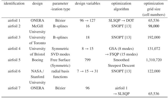
Information about the optimized airfoils and the approaches used is contained in table 1.
sat-Table 1 Information about optimized airfoils
identification design parameter design variables optimization optimization
-ization type algorithm grid size
(cell numbers)
airfoil 1 ONERA Bézier 96→127 SLSQP→DOT 65,536
airfoil 2 McGill B-splines 16 SNOPT [13] 98,000
University
airfoil 3 University B-splines 18 SNOPT [13] 192,000
of Toronto
airfoil 4 University Symmetric 8→15 GSA (8 modes) 131,072
of Bristol SVD modes →FSQP (15 modes)
airfoil 5 Boeing Free Surface 799 Smoothed 1,310,720
(Symmetric) Steepest Descent
airfoil 6 NASA/ radial basis 7→15→31 SNOPT [13] 122,000
Stanford functions University
airfoil 7 ONERA Bézier 96 airfoil 1
→SLSQP 65,536
isfy the thickness constraint, thicknessgreateror equal to the baseline airfoil thickness at all chordwise locations. All optimized airfoils have common features: a blunt leading edge, a “flat top”, a highly curved rear region and a large trailing edge included angle, which were also features of the optimized airfoils in [12]. However, as expected given the variety of the approaches (table 1), significant differences appear between their shapes.
III. Planned Assessment Protocol
The grids are based on some of the NACA0012 airfoil grids of Vassberg and Jameson [14]. These highly regular grids with quasi-orthogonal cells have an O-type topology with identical numbers of cells in the two directions. Ifncis this number, levelsnc =256,512,1024 are used in this study. The grid forlevelnc =256 for airfoil 1 is illustrated in figure 4. The metric properties of these grids were designed to ensure a quasi linear behavior of pressure drag with 1/nc2 for usual second order finite volume formulations. That was the case in [14], where extrapolation to zero mesh size was thus straightforward. It remained so for the various optimized airfoils produced by ONERA and compared in [1].
The optimized airfoils, requested to number at least 129 points, are transformed into series of 2048 points through spline interpolation. The NACA0012nc=2048 grid is then projected onto their shape. The resulting grid is coarsened to levelsnc=1024,512 and 256 for the resolution of the Euler equations.
The Euler solutions are computed with the ONERAelsAsoftware [15, 16]. As in the assessment computations of [1], the centred scheme of Jameson [17] with the JST artificial dissipation is used, dissipation coefficients being set to κ2=0.5, κ4=0.008. To facilitate convergence, a wall slip condition instead of a matching condition is applied to the grid lines joining the trailing edge and the downstream grid boundary, see figure 4.Based on previous experience, the default number of iterations for the present study was set to 5000, with 3 multigrid levels.
The planned protocol was, for each airfoil, to perform three computations, nc = 256,512,1024, at the unique design conditions,M∞ =0.85, α=0◦, and to extrapolate to zero mesh size through the procedure described in [14].
Things did not turn out asstraightforwardlyas anticipated and led to further investigations.
IV.
Initial
Investigations
The planned protocol was first systematically applied to the seven airfoils. Anomalies appeared for some of them. At this stage, it is enough to consider airfoils 1 and 2.
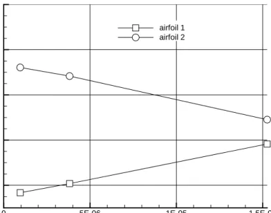
Convergence of the residual L∞ norm of variable ρis plotted in figures 5 and 6. For airfoil 1, convergence is as expected from common experience, reaching machine zero level and requiring more iterations with a finer grid level than with a coarser (figure 5). Such is not the case for airfoil 2 (figure 6), where machine zero level is reached with the coarsest and the finest grid but not with the medium grid. Pressure drag computation was still performed, though with dubious results. Indeed a striking anomaly affects the behavior of airfoil 2 pressure drag through grid refinement, plotted in figure 7. Pressure drag of airfoil 1 decreases with grid refinement because spurious drag [18] (mostly at the blunt leading edge) decreases, while the flow physics (shock waves) are notdisturbed. The opposite behavior with airfoil 2, added to the convergence anomaly,leads usto suspect some flow topology change with grid refinement.
Chordwise pressure coefficient distributions on airfoil 2 for the three grid refinement levels are plotted in figure 8. The topology change is from a unique supersonic/subsonic shock trace with the coarsest grid (thick line in the figure) toan initialsupersonic/subsonic shock trace followed by a strong expansion leading to a second supersonic/subsonic shock trace with the medium and fine grid.
This calls for several remarks: 1) the double shock pattern was not found by the designers of airfoil 2 who checked it with several solvers [2] and found consistently much lower dragcoefficientlevels (around 40 drag counts, not 90 as
in figure 7); 2) the difficult convergence with the medium grid must come from the fact that the flow is still closetothe topology change; 3) the double shock will produce much more wave drag than the unique shock (in the present case), which accounts for the anomaly of figure 7,which showsmuch higher drag with fine grid than with coarse grid.
As pointed out by Vassberg et al. in [12], to understand drag production with airfoils of the kind dealt with here, “one must inspect the flowfield, not just the properties on the airfoil surface”. This will be done extensively in a sub-sequent section entitledFinal assessment. Here such inspection is limited to the finest grid solutions for airfoils 1 and 2, figures 9 and 10 displaying supersonic iso-Mach number line patterns. Airfoil 1 shows a single supersonic area (for a half-airfoil), airfoil 2 a double supersonic area. Airfoil 1 produces a supersonic/subsonic shock at a distance in the field and, near the airfoil, a more complex structure consisting of a supersonic/supersonic shock followed by a short su-personic expansion and ending with a susu-personic/subsonic shock. Airfoil 2 produces an extended supersonic/subsonic shock in the field and a subsonic-to-supersonic expansion leading to a second less extended supersonic/subsonic shock. The first type of solution will be called solution of the first kind in this paper and the second type solution of the second kind.
V. Further Investigations
Airfoil 2 supports a solution of the first kind in [2] and with the coarsest grid of the present study, but a solution of the second kind with the finer grids. At this stage, an hypothesis could not be neglected, that of “non-unique solutions of a discrete model of the Euler equations” as first evidenced by Jameson [19], then by Hafez and Guo [20]. In [21], Jameson et al. produced other non-unique solutions for airfoils of the same type as those investigated in the present paper. Ou et al. [22] confirmed multiple solutions for airfoils from [21] in unsteady viscous flow. The same authors showed that the problem is not limited to 2D airfoils but may arise for wings as well [23].
Similar shock structures to those encountered in the present study are also discussed by Kuz’min and Ivanova in [24]: “singular free-stream Mach numbers, which trigger the splitting/amalgamation of local supersonic regions”. A physical interpretation of this phenomenon given by these authors is that in non-isentropic steady flow, the down-stream boundary of a supersonic area cannot physically be in contact with the updown-stream boundary of another supersonic area. So, when, through some infinitesimal perturbation, a unique supersonic area is split into two areas, the process must be discontinuous.
In these further investigations, it was chosen to take Mach number as the perturbation factor. Downward Mach number sweeps were computed with the coarsestnc=256 grid level for all airfoils, around the design Mach number
were started from the converged state atM∞+∆M∞. The prescribed number of iterations was 3000. Most computa-tions reached machine zero. When such was not the case, solucomputa-tions with uncertainty|∆CDp| ≥.01 drag count were rejected, hence the gaps seen in figures 11 and 12. The purpose of these tests was looking for solutions of the first and second kind and the topology change from one to the other. If an airfoil may support both kinds of solution, high Mach numbers are likely to produce the first kind, with a shock located close to the trailing edge. Indeed, for all airfoils, a solution of the first kind is obtained with the maximum Mach number M∞ =0.8505. When the Mach number is lowered, a solution of the second type is always obtained, but through two different mechanisms, one discontinuous, one continuous, see figures 11 and 12. All airfoils but airfoil 5 undergo a discontinuous jump from a solution of the first kind to a solution of the second kind through thesplitting of a singlesupersonic area into two as described in [24], with a correlative discontinuous drag increase. This occurs just below the design point Mach numberM∞ =0.85. It can be seen that airfoil 5 behaves differently from the other airfoils. The reason is that, for this airfoil, transition from a solution of the first kind to a solution of the second kind does not happen through thesplitting of a singlesupersonic area but through the appearance of a second, separate, continuously growing, supersonic area, with no contact with the primary one in the investigated range.
From these coarse grid results, three airfoils were selected for fine grid checking (nc =1024), and performing an upward Mach number sweep after the downward sweep. The objectives were to searchforhysteresis behavior which would account for multiple solutions, and to investigate probable transient non-symmetrical solutions (one ap-pears in figure 12 for airfoil 7). The chosen airfoils are airfoil 2 because of suspicion of multiple solutions, airfoil 5 for its unique continuous behavior and airfoil 7 the lowest drag airfoil at design conditions. The width of the ex-plored Mach number range is narrower than with coarse grids, between M∞ = .8490 and M∞ = .8505. The basic step,∆M∞ =±0.0001, has been empirically refined around discontinuities for airfoil 7 in search of non-symmetrical solutions.
CDp(M∞) curves are plotted in figure 13. For airfoils 2 and 7, this figure shows a lower drag branch and a
higher drag branch. During the downward Mach number sweep, the solution jumps from the lower branch to the higher branch, while in the upward sweep it jumps back to the lower drag branch. Hysteresis makes the two jump Mach numbers different. So, in a narrow Mach number band, double solutions may be obtained. The design Mach number,M∞ =0.85 is inside this band. The lower drag branch consists of solutions of the first kind, the upper drag branch of solutions of the second kind. With airfoil 5 a unique branch is found, with continuous transition from the first to the second kind through the development of a downstream supersonic area separated from the primary one.
through a non-symmetrical solution, first kind on the upper side, second kind on the lower side. Convergence of these three computations is plotted in figure 17. It isslowimmediately before the topology change,fastin the non-symmetrical case and immediately after the topology change. In the upward sweep, the non-non-symmetrical solution (second kind on the upper side, first kind on the lower side) is less transient than in the downward sweep.
It should be noted that a similar behavior was found for one of the present airfoils with an entirely different flow solver [6]: it is not an artefact of the solver used in this study.
The shock pattern of solutions of the first kind for airfoils 2 and 7 shows a long supersonic-subsonic wave away from the airfoil surface, broken down into a short supersonic-supersonic wave and a short supersonic-subsonic wave near the airfoil surface. This might be the feature which accounts at once for very low drag and instability. In solutions of the second kind, the pattern is simpler: two supersonic-subsonic waves separated by an expansion.
VI. Final Assessment
For airfoils 2 and 7 the existence of a lower drag branch over the design Mach number and of a higher drag branch below, with some overlap providing double solutions, has thus been evidenced. The lower drag branch consists of solutions of the first kind while the upper drag branch consists of solutions of the second kind. Figures 11 and 12 suggest that it might also be the case for airfoils 1, 3, 4, 6. So a modified assessment protocol taking advantage of the downward sweep hysteresis was devised: 2000 iterations atM∞ =0.8505+2000 iterations atM∞ =0.85025+ 5000 iterations atM∞ = 0.85. This procedureledcomputations of all airfoils susceptible of a double branch (1, 2, 3, 4, 6, 7) to lower drag branch solutions of the first kind, see figures 18, 19, 20, 21, 23, 24. In the case of airfoil 5, which does not have a branchat the design point, the solution shows a single supersonic area (for a half-airfoil), figure 22, but the iso-Mach number line pattern is not strictly of the first kind. A close look at figure 22 does show a short supersonic/supersonic wave, but this wave is detached from the airfoil.
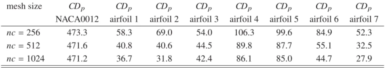
Computed pressure drag coefficient values are gathered in table 2 and figure 25. With the modified assessment protocol, for all airfoils drag decreases as the grid is being refined, compare figure 25 to figure 7. Extrapolation to zero mesh size was attempted following the method of [14]. The measured order of accuracy with this method varies between 1.5 and 2.2 depending on the airfoil considered. But considering the coarseness of levelnc = 256 and the imperfect linear behavior for some airfoils, extrapolated data were not retained.
Different grid dependency slopes in figure 25 reflect different levels of spurious drag. More or less blunt lead-ing edges will induce more or less spurious drag because spurious drag at the leadlead-ing edge is influenced by pressure
gradients. This can be illustrated by comparing the curvature of airfoils 3 and 6 in figure 26. Curvature is computed with the reduced curvilinear abscissa parameter, 0 at the lower side trailing edge, 0.5 at the leading edge, 1 at the upper side trailing edge. Airfoil 6 is much blunter than airfoil 3. Consistently, the grid dependency slope in figure 25 is much higher for airfoil 6 than for airfoil 3. A normally rounded leading edge such as the NACA0012’s produces weaker pressure gradients than the blunt leading edges of the airfoils investigated here. (With an inviscid flow model, a squared leading edge would induce infinite pressure gradients.) The much larger amounts of spurious drag with the optimized shapes than with the NACA0012 is obvious in table 2.
If the differences in grid dependency slope arise from numerical effects (spurious drag), those in finest grid drag level arise mostly from physical phenomena (wave drag). All airfoils but one support a shock structure of the first kind, airfoils 1, 2, 3, 4, 6, 7. However there are differences between these structures (figures 18, 19, 20, 21, 23, 24). An attempt at identifying a relation between drag and the length of the supersonic/supersonic wave is presented in figure 27 with an exponential fit at the data points. It is acknowledged that the length measurement involves a part of subjectivity, but the ambition is only to identify this supersonic wave length as a major factor in wave drag production in solutions of the first kind. It is obvious that there must be other shock features that contribute to the wave drag variation, such as shock angle and curvature.
Table 2 Grid convergence of pressure drag coefficient (expressed in drag counts)
mesh size CDp CDp CDp CDp CDp CDp CDp CDp
NACA0012 airfoil 1 airfoil 2 airfoil 3 airfoil 4 airfoil 5 airfoil 6 airfoil 7
nc=256 473.3 58.3 69.0 54.0 106.3 99.6 84.9 52.3
nc=512 471.6 40.8 40.6 44.5 89.8 87.7 55.1 32.5
nc=1024 471.2 36.7 31.8 42.4 86.1 85.0 44.7 27.9
VII. Conclusion
One of the test-cases of the AIAA Aero-Design Optimization Discussion Group is based on the NACA0012 airfoil with solutions of the Euler equations. The purpose of the present study was to provide a pressure drag assessmant of the optimized shapes by several participants through grid convergence. It had been anticipated thatthisstudy would be straightforward and dull. Fortunately, initial investigations produced anomalies and raised questions. Further investigations, much inspired by Jameson’s 1991 paper on non-unique numerical solutions of the Euler equations and Jameson et al. sequel of 2012, showed that for most of the airfoils investigated there exists a lower drag branch and a higher drag branch in thedrag coefficient vs. Mach numberdiagram. Hysteresis when performing a downward Mach number sweep and an upward Mach number sweep was such that, for several airfoils, the design point was inside
the overlap range of the two branches, which means a double solution at this point. A low drag converged solution or a high drag converged solution could be found depending on thehistory of the computation. Dependency on computation history is rather unwelcome in CFD but cannot be ignored.Two typical structures of supersonic flow were distinguished. One consists in a single supersonic flow area containing a supersonic/supersonic wave starting from the airfoil surface. The other involves two separate supersonic flow areas without a supersonic/supersonic wave. The jump from one branch to the other is due to flow topology change from one kind to the other. The first kind produces a lower drag branch, the second kind a higher drag branch. The topology change from one kind to the other may involve non symmetrical converged solutions, of the first kind on one side of the airfoil and of the second kind on the other. For the final assessment, a procedure that takes advantage of the hysteresis was used to ensure capture of the lower drag branch at the design point. Reliable drag dependency on grid refinement was thus obtained. A relation between the drag efficiency and the length of the supersonic/supersonic wave has been proposed. All airfoils but one admit two branches, the optimum being a solution of the first kind. The airfoil behaving differently is of neither kind. It supports asinglesupersonic area but the supersonic wave is separated from the airfoil. Its drag level is among the highest, but its behavior in a Mach sweep is continuous, as if excellence in single-point drag minimization in highly transonic flow involved the drawback ofinstabilityin the vicinity of the optimum.Theconclusion of Jameson’s 1991 paper contains the warning thatoptimization does not necessarily lead to a good design.As regards nonunique solutions, which have been identified by other authors, although there is no reason why they might not occur with shapes not derived from optimization, the present paper indicates a strong correlation between optimality and nonuniqueness: six of the seven optimized airfoils support nonunique solutions.
For the airfoils apt to support multiple solutions, the optimization algorithms used by the various participants always led to the lower drag branch, which is satisfactory for the ADO-DG purpose. However, nonuniqueness may have negative effect on convergence of an optimization algorithm (as the same set of design variables can give two different objective function values). The present paper, concentrating on numerical flow physics investigations, does not contain a critical discussion of the different optimization methods or parameterizations. From the data produced here, a follow-up paper dedicated to such a discussion might be of interest. However the present paper already provides an overview of the status of the optimization results obtained by the different teams having worked on the ADO-DG test case # 1 during the two first years since its creation. It will also, hopefully, encourage new participants to investigate this optimization test case and try to achieve designs even closer to a shock-free airfoil.
References
[1] Carrier, G., Destarac, D., Dumont, A., Méheut, M., Salah El Din, I., Peter, J., Ben Khelil, S., Brézillon, J., Pestana, M.,
“Gradient-Based Aerodynamic Optimization with theelsASoftware,” AIAA Paper 2014-0568,AIAA SciTech 52nd Aerospace
[2] Bisson, F., Nadarajah, S., Shi-Dong, D., “Adjoint-Based Aerodynamic Optimization of Benchmark Problems,” AIAA Paper
2014-0412,AIAA SciTech 52nd Aerospace Meeting, 13-17 January 2014, National Harbour, MD.
[3] Bisson, F., Nadarajah, S., “Adjoint-Based Aerodynamic Optimization of Benchmark Problems,” AIAA SciTech 53rd Aerospace
Sciences Meeting, 5-9 January 2015, Kisseemee, FL, doi: 10.2514/6.2015-1948.
[4] Hicken, J.E., Zingg, D.W., “Aerodynamic Optimization Algorithm with Integrated Geometry Parameterization and Mesh
Move-ment,”AIAA Journal,Vol. 48, No. 2, 2010, pp. 401-413, doi: 10.2514/1.44033.
[5] Telidetzki, K., Osusky, L., Zingg, D.W., “Application of Jetstream to a Suite of Aerodynamic Shape Optimization
Prob-lems,” AIAA Paper 2014-0571, AIAA SciTech 52nd Aerospace Meeting, 13-17 January 2014, National Harbour, MD, doi:
10.2514/6.2014-0571.
[6] Lee, C., Koo, D., Telidetzki, K., Buckley, H., Gagnon, H., Zingg, D.W., “Aerodynamic Shape Optimization of Benchmark
Prob-lems Using Jetstream,” AIAA SciTech 53rd Aerospace Sciences Meeting, 5-9 January 2015, Kisseemee, FL, doi: 10.2514/
6.2015-0262.
[7] Poole, D.J., Allen, C.B., Rendall, T.C.S., “Control Point-Based Aerodynamic Shape Optimization Applied to AIAA ADODG
Test Cases,” to Two-Dimensional Drag Minimization,” AIAA SciTech 53rd Aerospace Sciences Meeting, 5-9 January 2015,
Kisseemee, FL, doi: 10.2514/6.2015-1947.
[8] LeDoux, S., Vassberg, J.C., Young, D., Fugal, S., Kamenetskiy, D., Huffman, W., Melvin, R., Smith, M., “A Study Based on
the AIAA Aerodynamic Design Optimization Workshop Test Cases,”AIAA Journal,Vol. 53, No. 7, 2015, pp. 1910-1935, doi:
10.2514/1.J053535.
[9] Anderson, G.R., Aftosmis, M.J., Nemec, M., “Aerodynamic Shape Optimization Benchmarks with Error Control and
Automatic Parameterization,” AIAA SciTech 53rd Aerospace Sciences Meeting, 5-9 January 2015, Kisseemee, FL, doi:
10.2514/6.2015-1719.
[10] Méheut, M., Destarac, D., Carrier, G., Anderson, G., Nadarajah, S., Poole, D., Vassberg, J.C., Zingg, D.W., “Gradient-Based
Single and Multi-Point Aerodynamic Optimizations with theelsASoftware,” AIAA SciTech 53rd Aerospace Sciences Meeting,
5-9 January 2015, Kisseemee, FL, doi: 10.2514/6.2015-0263.
[11] https://info.aiaa.org/tac/ASG/APATC/AeroDesignOpt-DG/Test Cases/ADODG Base 1 and 2 NACA0012 and RAE 2822.pdf
[12] Vassberg, J.C., Harrison, N.A., Roman, D.L., Jameson, A., “A Systematic Study on the Impact of Dimensionality for a
Two-Dimensional Aerodynamic Optimization Model Problem,” AIAA Paper 2011-3176, 29th AIAA Applied Aerodynamics
Conference, 27-30 June 2011, Honolulu, HI, doi: 10.2514/6.2011-3176.
[13] Gill, P.E., Murray, W., Saunders, M.A., “SNOPT: An SQP Algorithm for Large-Scale Constrained Optimization,”SIAM
[14] Vassberg, J.C. and Jameson, A., “In Pursuit of Grid Convergence for Two-Dimensional Euler Solutions,”Journal of Aircraft,
Vol. 47., No. 4, July-August 2010, pp.1152-1166, doi: 10.2514/1.46737.
[15] Cambier, L., Veuillot, J.-P., “Status of theelsASoftware for Flow Simulation and Multi-Disciplinary Applications,” AIAA
Paper 2008-664,46th AIAA Aerospace Sciences Meeting and Exhibit, Reno, NV, January 2008, doi: 10.2514/6.2008-664.
[16] Cambier, L., Heib, S., Plot, S., “The OneraelsACFD Software: Input from Research and Feedback from Industry,”Mechanics
&Industry, Vol. 14, No. 3, April 2013, doi: 10.1051/meca/2013056 .
[17] Jameson, A., Schmidt, W., Turkel, E., “Numerical Solution of the Euler Equations by Finite Volume Methods Using
Runge-Kutta Time-Stepping Schemes,” AIAA Paper 1981-1259,AIAA 14th Fluid and Plasma Dynamic Conference, Palo Alto, CA,
23-25 June 1981, doi: 10.2514/6.1981-1259.
[18] Destarac, D., “Far-Field/Near-Field Drag Balance and Applications of Drag Extraction in CFD,” VKI Lecture Series 2003,
CFD-based Aircraft Drag Prediction and Reduction, von Karman Institute for Fluid Dynamics, Rhode Saint Genèse, February 3-7, 2003.
[19] Jameson, A., “Airfoils Admitting Non-Unique Solutions to the Euler Equations,” AIAA Paper 1991-1625,AIAA 22nd Fluid
Dynamics, Plasmadynamics&Lasers Conference, 24-26 June 1991, Honolulu, HI, doi: 10.2514/6.1991-1625.
[20] Hafez, M.M., Guo, W.H., “Nonuniqueness of Transonic Flows,”Acta Mech., Vol. 138, Nos. 3-4, 1999, pp. 177-184, doi:
10.1007/BF01291843.
[21] Jameson, A., Vassberg, J.C., Ou, K, “Further Studies of Airfoils Supporting Non-Unique Solutions in Transonic Flow,”AIAA
Journal, Vol. 50, No. 12, December 2012, pp.2865-2881, doi: 10.2514/1.J051713.
[22] Ou, K., Jameson, A., Vassberg, J.C., “Airfoils Supporting Non-unique Transonic Solutions for Unsteady Viscous Flows,”
AIAA Paper 2014-2927,AIAA Aviation, 7th AIAA Theoretical Fluid Mechanics Conference16-20 June 2014, Atlanta, GA, doi:
10.2514/6.2014-2927.
[23] Ou, K., Jameson, A., Vassberg, J.C., “Studies of Wings Supporting Non-unique Solutions in Transonic Flows,” AIAA Paper 2014-2928, AIAA Aviation, 7th AIAA Theoretical Fluid Mechanics Conference16-20 June 2014, Atlanta, GA, doi: 10.2514/6.2014-2928.
[24] Kuz’min, A.G., Ivanova, A.V., “The structural Instability of Transonic Flow Associated with Amalgamation/Splitting of
Supersonic Regions,”Theoretical and Computational Fluid Dynamics, Vol.18, No.5, 2004, pp.335-344, doi: 10.1007/
s00162-004-0145-1.
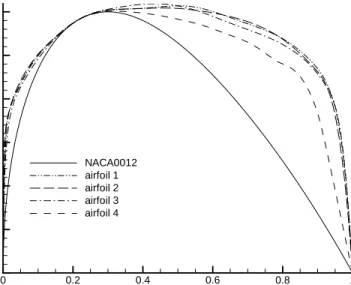
X Y 0 0.2 0.4 0.6 0.8 1 0 0.01 0.02 0.03 0.04 0.05 0.06 NACA0012 airfoil 1 airfoil 2 airfoil 3 airfoil 4
Fig. 1 Baseline and optimized shapes (1)
X Y 0 0.2 0.4 0.6 0.8 1 0 0.01 0.02 0.03 0.04 0.05 0.06 NACA0012 airfoil 5 airfoil 6 airfoil 7
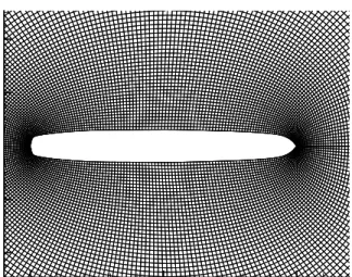
x y 0 0.5 1 -0.4 -0.2 0 0.2 0.4
Fig. 3 Grid of levelnc=256(airfoil 1)
wall slip
wall slip
Fig. 4 Extension of the wall slip condition along the downstreamz =0grid line (going to the infinite down-stream boundary, not visible in the figure)
iteration ρ re si d u a l n o rm 1000 2000 3000 4000 5000 10-12 10-10 10-8 10-6 10-4 10-2 100 102 104 nc=1024 nc=512 nc=256
iteration ρ re si d u a l n o rm 1000 2000 3000 4000 5000 10-12 10-10 10-8 10-6 10-4 10-2 100 102 104 nc=1024 nc=512 nc=256
Fig. 6 Airfoil 2.Convergence ofL∞norm residual ofρ
1/nc2 C D p (d .c. )
0 5E-06 1E-05 1.5E-05
40 60 80 100 120 airfoil 1 airfoil 2
X C p 0 0.2 0.4 0.6 0.8 1 -1.5 -1 -0.5 0 0.5 1 airfoil 2 nc=256 airfoil 2 nc=512 airfoil 2 nc=1024
Fig. 8 Airfoil 2. Planned protocol. Chordwise pressure coefficient distributions
x y 0 0.5 1 -0.4 -0.2 0 0.2 0.4
x y 0 0.5 1 -0.4 -0.2 0 0.2 0.4
Fig. 10 Airfoil 2,nc=1024grid, planned protocol - supersonic iso-Mach number lines (∆M =0.025)
M C D p 0.846 0.847 0.848 0.849 0.85 0.851 40 60 80 100 120 140 airfoil 1 airfoil 2 airfoil 3 airfoil 4
M C D p 0.846 0.847 0.848 0.849 0.85 0.851 40 60 80 100 120 140 airfoil 5 airfoil 6 airfoil 7
Fig. 12 Coarse grid downward Mach number sweep for airfoils 5, 6, 7
M C D p (d .c. ) 0.8490 0.8495 0.85 0.8505 20 40 60 80 100 120 airfoil 2 airfoil 5 airfoil 7
x y 0.4 0.6 0.8 1 -0.2 0 0.2
Fig. 14 Airfoil 7,nc =1024grid - downward Mach number sweep, M∞ =0.849425- supersonic iso-Mach number lines (∆M=0.025) x y 0.4 0.6 0.8 1 -0.2 0 0.2
Fig. 15 Airfoil 7,nc =1024grid - downward Mach number sweep,M∞ =0.8494245- supersonic iso-Mach number lines (∆M=0.025)
x y 0.4 0.6 0.8 1 -0.2 0 0.2
Fig. 16 Airfoil 7,nc =1024grid - downward Mach number sweep, M∞ =0.849424- supersonic iso-Mach number lines (∆M=0.025) iteration ρ re si d u a l n o rm 500 1000 1500 2000 2500 3000 10-12 10-10 10-8 10-6 10-4 10-2 100 102 104 1) symmetrical type 1 2) non-symmetrical type 1 / type 2 3) symmetrical type 2
Fig. 17 Airfoil 7,nc =1024. Convergence ofL∞ norm residual of ρat flow topology change from type 1 to type 2.
x y 0 0.5 1 -0.4 -0.2 0 0.2 0.4
Fig. 18 Airfoil 1, lower drag branch,nc=1024- supersonic iso-Mach number lines (∆M =0.025)
x y 0 0.5 1 -0.4 -0.2 0 0.2 0.4
x y 0 0.5 1 -0.4 -0.2 0 0.2 0.4
Fig. 20 Airfoil 3, lower drag branch,nc=1024grid - supersonic iso-Mach number lines (∆M =0.025)
x y 0 0.5 1 -0.4 -0.2 0 0.2 0.4
x y 0 0.5 1 -0.4 -0.2 0 0.2 0.4
Fig. 22 Airfoil 5, unique drag branch,nc=1024grid - supersonic iso-Mach number lines (∆M =0.025)
x y 0 0.5 1 -0.4 -0.2 0 0.2 0.4
x y 0 0.5 1 -0.4 -0.2 0 0.2 0.4
Fig. 24 Airfoil 7, lower drag branch,nc=1024grid - supersonic iso-Mach number lines (∆M =0.025)
1/nc2 C D p (d .c. )
0 5E-06 1E-05 1.5E-05
20 40 60 80 100 120 airfoil 1airfoil 2 airfoil 3 airfoil 4 airfoil 5 airfoil 6 airfoil 7
reduced curvilinear abscissa c u rv a tu re 0.4 0.45 0.5 0.55 0.6 0 20 40 60 80 100 120 airfoil 3 airfoil 6
Fig. 26 Curvature of airfoils 3 and 6 (detail)
supersonic wave length / chord
C D p (d .c .) 0 0.1 0.2 0.3 0.4 0.5 0 10 20 30 40 50 60 70 80 90