XIX CICLO
UNIVERSITA DEGLI` STUDI DI MODENA EREGGIO EMILIA Dipartimento di Ingegneria dell’Informazione
TESI PER IL CONSEGUIMENTO DEL TITOLO DI DOTTORE DI RICERCA
Computer Vision for
People Video Surveillance
Tesi di:
Dott. Ing. Roberto Vezzani Relatore:
1 Computer Vision based Surveillance Systems 17
1.1 Introduction . . . 17
1.2 Related Work in Video Surveillance . . . 19
1.3 Thesis Overview . . . 20
I Object Detection and Tracking 23 2 Fixed Cameras: the Sakbot system 25 2.1 Introduction . . . 25
2.2 Background suppression . . . 27
2.3 Shadow detection . . . 30
2.4 Conclusions . . . 31
3 Pan Tilt Cameras 33 3.1 Introduction . . . 33 3.2 Background mosaiking . . . 33 3.3 Experimental Results . . . 37 3.4 Conclusions . . . 39 4 Moving Cameras 41 4.1 Introduction . . . 41 4.2 Related Work . . . 42
4.3 Description of the proposed approach . . . 48
4.3.1 Color segmentation . . . 51
4.3.2 Partitioned Region Matching (PRM) . . . 52
4.3.3 Region level MRF . . . 56
4.3.4 Background and moving object identification . . . 58
4.4 Experimental results . . . 58
4.4.1 “Object sequence” . . . 58
4.4.2 “Indoor sequence” . . . 61
4.4.3 “Hand sequence” . . . 62
4.4.4 Computational performance analysis . . . 62
4.6 Performance analysis on the modified algorithm . . . 67
4.6.1 Processing times . . . 67
4.6.2 Qualitative metrics . . . 67
4.7 Conclusions . . . 69
5 Appearance Based Tracking 71 5.1 Introduction . . . 71
5.2 Related works . . . 74
5.3 The Tracking Algorthm . . . 76
5.4 Position optimization . . . 77
5.4.1 Pixel to Track Assignment . . . 80
5.4.2 Shape changes and new objects detection . . . 81
5.4.3 Occlusion Detection and Classification . . . 83
5.4.4 Refinements . . . 86
5.5 Experiments . . . 88
5.5.1 Results on the PETS 2006 dataset . . . 91
5.6 Conclusions . . . 95
II People VideoSurveillance 97 6 Human motion capture and behavior analysis 99 6.1 Introduction . . . 99
6.2 Related works . . . 100
6.3 Projection Histograms . . . 103
6.4 Frame by Frame Classification . . . 103
6.5 Scaling Procedure . . . 105
6.6 Support Point Tracking . . . 106
6.7 Probabilistic Projection Maps (PPMs) . . . 107
6.8 Track-based Classification . . . 111
6.9 HMM Framework for Posture Classifier . . . 113
6.10 Experimental Results . . . 114
6.10.1 Frame by Frame classifier and STG . . . 114
6.10.2 Results of the HMM approach . . . 118
6.11 Discussion and Conclusions . . . 118
7 Face detection 121 7.1 Video-Surveillance and Biometry . . . 121
7.2 Head detection . . . 124
7.2.1 Related works . . . 124
7.2.2 Head model . . . 125
7.3 Integration with the motion detection module . . . 127
7.4 Hough Transform for Face Detection . . . 129
7.5 Experimental Results . . . 130
7.6 Conclusion . . . 130
III Integrated VideoSurveillance Systems 133 8 Multicamera Systems 135 8.1 Introduction and Related Work . . . 135
8.2 Detecting Overlapping Areas . . . 136
8.3 Consistent Labeling with Homography . . . 138
8.4 Camera Transition Graph . . . 140
8.5 Track warping . . . 141
8.6 Experimental Results . . . 145
8.7 Conclusions . . . 147
9 Geospatial Trajectory Estimation of a Moving Camera 149 9.1 Introduction . . . 149
9.2 Description of the system . . . 150
9.3 Related works . . . 150
9.4 Image Localization . . . 152
9.4.1 Estimating the Weighted Adjacency Matrix . . . 153
9.4.2 Pose Recovery of the Novel Images . . . 154
9.4.3 Resolving Scale Ambiguity . . . 154
9.5 Video Localization . . . 156
9.5.1 Localization of the Video Frames . . . 157
9.5.2 Trajectory Smoothing . . . 157
9.6 Results and Discussion . . . 157
9.7 Conclusions . . . 162
10 Sensor Integration 163 10.1 Introduction . . . 163
10.2 Related works . . . 164
10.3 Integrated Multi-Modal Sensor Network . . . 165
10.4 PIR sensor network . . . 166
10.4.1 Sensor node architecture . . . 166
10.4.2 Sensing and Acquisition Software . . . 168
10.4.3 Network Architecture . . . 170
10.5 Examples of Multi-modal Integration . . . 171
10.5.1 Sensor-guided Background Update . . . 171
11 Semantic Video Transcoding 175 11.1 Introduction . . . 175 11.2 Inter-media transcoding . . . 177 11.2.1 3D virtual environment . . . 177 11.3 Software components . . . 178 11.4 Experiments . . . 180 11.5 Intra-media Transcoding . . . 180 11.5.1 Introduction . . . 180 11.5.2 Related Works . . . 181 11.5.3 System Architecture . . . 181
11.5.4 Transcoding Server and PDA Client Application . . . 182
11.6 Experimental Results . . . 184
11.7 Conclusions . . . 186
12 Conclusions 187 12.1 Achieved Objectives . . . 187
1.1 Overall Scheme of a People Video surveillance System . . . 21
2.1 Validation rules . . . 29
2.2 Comparison of the results achieved by preserving or removing shad-ows: (a) is the input frame, (b) the extracted V O by including shadows and (c) that obtained by removing shadows. . . 31
2.3 Results of the shadow removal algorithm obtained with different parameters. a) and c) are the input frames, while b), d), e), and f) are the outputs of the shadow detector: white pixels correspond to shadows. . . 32
3.1 Example of extraction and clustering of the motion vectors . . . . 34
3.2 Direction histograms before and after the application of gaussian filter . . . 35
3.3 Result of the motion vector clustering in the case of a person mov-ing in the same direction of the camera. . . 36
3.4 Frame differencing (a) without and (b) with ego-motion compen-sation . . . 37
3.5 Active contours: input edge image, external energy image and the resulting snake . . . 37
3.6 An example of mosaic image. . . 38
3.7 Snapshots from a live sequence with person following. . . 38
4.1 The block diagram of the proposal . . . 50
4.2 Example of partitioned region matching (PRM). (a)(b) two consec-utive frames whereR1is the only moving object, (c)(d) two possi-ble matches ofR6, obtained with(vx, vy) = (0,0)and(vx, vy) = (1,1)respectively, (e)(f)SADRvalues with Eq. 4.2, the columns Ri in (f) are the number of pixel matching R6 −Ri that must weighted with the correspondent distancedin color (e.g., first row: 6210 = 22·235 + 12·55 + 7·25 + 1·205), (g) parts creation for PRM; (h) best match with PRM, (i) probabilities of the motion vectors . . . 55
output (in this frameO5 is not in motion). . . 59 4.4 Errors expressed in percentage of the total (in pixels) over object
sequence. The values refer to objects in motion (different from the background). Thus, false negatives are moving objects’ points that are not detected and false positives are points of still objects or of the background labeled as belonging to moving objects. . . 60 4.5 Frame 140 from indoor sequence: a) original frame, (b) after color
segmentation with region growing, (c) moving objects reported on output. (d) Output of frame 50, with a background’s region wrongly merged with the foreground moving object. . . 60 4.6 Positives and negatives (as in Fig. 4.4) over the indoor sequence . 61 4.7 Hand sequence: (a) an original frame, (b) after color segmentation,
and (c) output . . . 61 4.8 False negatives and positives (as in Fig. 4.4) over the hand sequence 62 4.9 Processing time vs. number of regions (on object sequence 200x200) 63 4.10 Possible graph inconsistence during arc based optimization . . . . 66 4.11 Computational time for arc based MRF optimization (on object
sequence 200x200) . . . 67 4.12 False negatives and positives (as in Fig. 4.4) over the hand
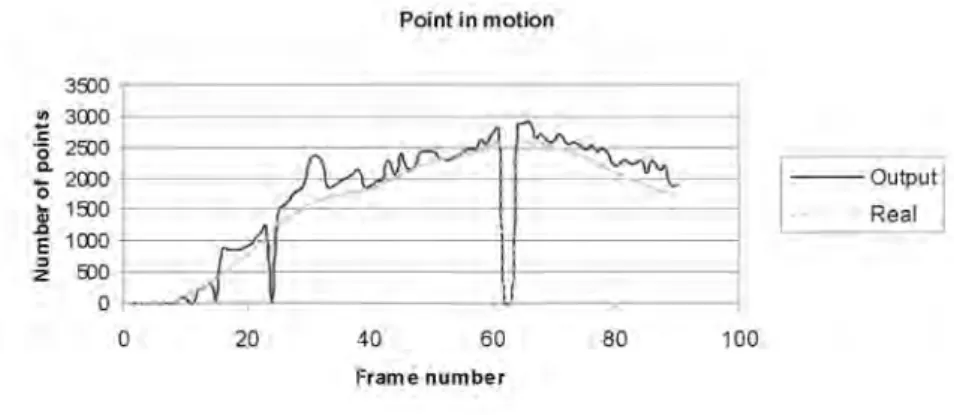
se-quence with arc-based optimization . . . 68 4.13 Points in motion on hand sequence calculated with arc based
opti-mization . . . 68 5.1 Domain and Codomain of the functiongO. gOtransforms the
co-ordinates of a foreground pixelx∈F to the correspondent object coordinates. . . 78 5.2 Visible and non visible part of an object. F˜is the foreground part
not covered by an object. . . 79 5.3 (a-d): sample frames; (e) number of assigned point aik and aki
during the occlusion. (f) Probabilities of occlusion P o(Oi, Oj)t
andP o(Oj, Oi)t. . . 82
5.4 An example of loss of part of the model because of an occlusion, if the model does not takes into account occluded pixels and works on assigned pixels only. (a) Input frame; (b) Current segmenta-tion; (c) Appearance Memory model and Probability mask without handling occlusions. The trajectory in (b) changes the direction because of the loss of the memory of the people legs. . . 83 5.5 Example of erroneous track freezing in case of occlusion. (a)
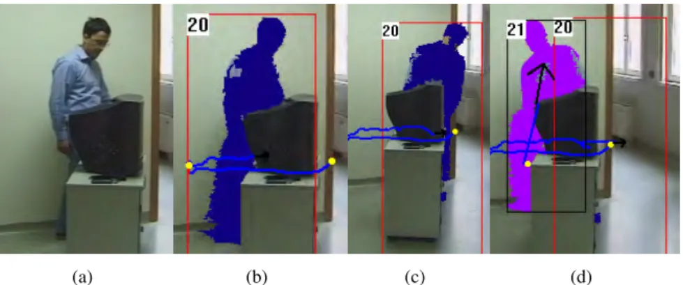
Orig-inal image; (b) an occlusion causes the percentage of visible pixels to became too low and the model updated is stopped; (c) the track andV Omatching is still maintained; (d) the track 20 is lost and the new track 21 is created because of the change of shape. . . 84
ground model (d) The visible part of the track (blue) and the can-didate occlusion regions (red).(e) the borders of the Non Visible Regions. Points that have a good match with edge pixels of the background are marked in black. ThusR1 is classified as aRBO
region whileR2as aRAO region. . . 86
5.7 (a-c) a person falls on the ground. (d-f) The probability masks show an apparent occlusion in correspondence of the legs. . . 87 5.8 Merge. (a) input frame; (b) two objects created; (c) the objects are
merged . . . 87 5.9 Split. (a) a single object for two people separating; (b) the
prob-ability mask where two different components are visible; (c) the object is split in two objects . . . 88 5.10 Example of background object occlusion. (a) A composition of
the input frames. (b) Pixel Assignment. (c) Temporal evolution of the appearance model of one of the tracks in case the background object occlusions are not handled. (d) The same appearance model with the handling ofBOOs. . . 89 5.11 Sample frames of the videos of Table 5.1 . . . 90 5.12 Video S1V3; sample output sequence of the tracking system during
the crossing of two people behind a plexiglass . . . 91 5.13 Video S2V3 and S2V4; handling of complex situations and
inter-actions . . . 93 5.14 Video S3V3; example of object split due to a baggage left . . . 93 5.15 Video S1V3; another example of object split due to a baggage left 94 5.16 Video S1V4; dynamic occlusion correctly managed . . . 94 5.17 Video S4V3; object split . . . 94 5.18 Video S1V3; The Merge algorithm used to connect two split parts
(torso and feet) of the same person. . . 95 6.1 Example of projection histograms. . . 104 6.2 Comparison of the projection histograms obtained by preserving
or removing shadows . . . 104 6.3 Model for perspective effect removal. (a) lateral view and (b) upper
view of the pin-hole camera model. Figure (c) reports the original frame, whereas (d) shows the undistorted image obtained through an homography on planeZ = 0. . . 106 6.4 SP tracking with Kalman Filters. Trajectories of SP estimated over
the blob (black color) and tracked with the Kalman Filter (white color) . . . 108 6.5 Example of PPMs compared with projection histograms (a), sparse
PPMs (b), and dense PPMs (c) forStandingf rontalposture. Brighter
6.8 An example ofp(Ci)dependent on the class. . . 113
6.9 Graph reporting the comparison on the video of the test type 1. . . 116 6.10 Graph reporting the comparison on the video of the test type 4. . . 117 6.11 Comparison between the frame-by-frame posture classification (a)
and the probabilistic classification with HMM (b) in presence of occlusions (c). . . 118 7.1 The elliptical face model adopted for the head detection. The size
ratio and the orientation are fixed. . . 125 7.2 Face detection over the foreground obtained with a background
subtraction algorithm . . . 128 7.3 Search area obtained with the dynamic mosaicing algorithm and
the detected head . . . 128 7.4 Input frames where the corresponding search areas have been
su-perimposed. The size of the search area is dependent on the motion of the tracked person. . . 129 7.5 Computation of the elliptical Hough transforms . . . 130 7.6 Some results obtained; left column: original frames with
superim-posed ellipses representing the head; middle column: results of the motion segmentation (the areas colored in gray are classified by the system as shadows); right column: Hough transform values (darker color indicates an higher probability value of the head center). . . 131 7.7 Results of the face detector algorithm in indoor surveillance. . . . 132 7.8 Examples of: face obscuration (a) and avoidable face obscuration (b)132 8.1 Map of our real setup. . . 137 8.2 Camera handoff. a. Simultaneous camera handoff of two tracks; b.
E2oF oV creation; c.EoF oV creation (using Khan-Shah approach) 138 8.3 Example of simultaneous crossing of two merged objects (frame
#1250, and split after entered at frame #1260 . . . 139 8.4 Point sets used for computation of the ground plane homography
between two different cameras . . . 139 8.5 Example of Camera Transition Graph (CTG). . . 140 8.6 The frame extracted from the two cameras during the camera
hand-off. The lines are the intersections of the floor and the gate plane computed and drawn by the system . . . 142 8.7 A scheme of the two rooms used for our tests . . . 142 8.8 Track warping: (1) exploiting the calibration of Camera1, (2)
tersection with entrance plane, (3) calibration of camera2, (4) in-tersection with Camera2 plane. . . 144 8.9 Initial occlusion resolved with track warping. a,d: input frames;
visibility over the three different cameras of the track used to gen-erate the trajectory . . . 145 8.11 Some snapshots of the output of the system after consistent labeling. 146 8.12 Visibility and labels (indicated with the color of the bars) of the
tracks in a test sequence . . . 146 9.1 Overall geospatial image localization scheme. . . 152 9.2 Triangulation between two reference images and novel image used
to resolve scale ambiguity for GPS location estimation. . . 155 9.3 Example of best triplet selection and matching for novel image of
Engineering building dataset. The two reference images are in top row while the novel image is in the bottom row. . . 155 9.4 Overall geospatial video localization scheme. . . 156 9.5 Examples of reference images with known GPS locations used in
our experiments. . . 158 9.6 Video frames for the theater sequence. Bottom: Video trajectory
(green) obtained using the temporal fundamental matrix based lo-calization method is compared with ground truth trajectory (red). The trajectory obtained through the fundamental matrix localiza-tion is shown in blue (yellow line shows non-smooth trajectory). The location of the reference images used in localization are shown as purple dots. . . 159 9.7 Video frames for the health sequence. Bottom: Video trajectory
(green) obtained using the temporal fundamental matrix based lo-calization method is compared with ground truth trajectory (red). The trajectory obtained through the fundamental matrix localiza-tion is shown in blue (yellow line shows non-smooth trajectory). The location of the reference images used in localization are shown as purple dots. . . 160 9.8 Localization error for 40 runs of the Theater sequence; mean
esti-mation error for each keyframe with standard deviation shown as top/bottom bars. . . 160 9.9 Images with unknown GPS location for Test4. Bottom: GPS
lo-cations (blue) obtained using our method is compared with ground truth GPS (red). The error in estimates are shown as yellow lines between the ground truth and estimated locations. . . 161 9.10 Images with unknown GPS location for Final5. Bottom: GPS
lo-cations (blue) obtained using our method is compared with ground truth GPS (red). The error in estimates are shown as yellow lines between the ground truth and estimated locations. . . 161 10.1 Map of our test bed system . . . 165
10.4 Signals detected by sensor: when a person passes through the area under control from left to right the first peak is negative and from right to left the first peak is positive . . . 168 10.5 Event acquisition and Sensor Data Conditioning and Processing . 169 10.6 Sensor node composed by two PIR sensors . . . 169 10.7 Activation sequence. . . 170 10.8 Communication protocol between nodes and sensor manager . . . 171 10.9 Opening and closeing doors make unreliable background
suppres-sion techniques . . . 172 10.10Sensor-guided background update. . . 173 10.11Consistent labelling after an occlusion exploiting a PIR sensor node
to detect direction changes . . . 174 11.1 Scheme of the overall architecture. . . 176 11.2 Input frame from a monitored room (left) and the output of the
video surveillance module (right) corresponding to the virtual re-construction of Fig. 11.4. Blobs, positions, and postures of the detected people are super-imposed. . . 177 11.3 Tree structure of the 3D virtual environment . . . 179 11.4 Example of different views of a3D virtual environment. a) standard
view, b) interactive view, c) bird-eye view. . . 180 11.5 Example of HTTP stream produced and sent from the server to the
client . . . 183 11.6 PSNR results for each frame, divided into classes and comparison
with the other algorithms . . . 185 11.7 Example of content-based video adaptation. . . 186
1 Symbols and Conventions . . . 15 2.1 Compared background subtraction approaches. Our approach is
referred with[1]. . . 26 2.2 Empirically determined parameters . . . 31 4.1 A review of related work. . . 45 4.2 Size and centroid coordinates estimation errors on object sequence.
The size mean error of the circle is carried out only in percentage because the circle is entering on the scene and its size is not fixed . 59 4.3 Processing time dependencies from parameters. In the first three
rows the parameters are scaled with the dimension, while in the other three are fixed. . . 62 4.4 Times (in seconds) for motion estimation vs. maximum shift. Frame
size: 100x100 . . . 63 5.1 Execution times in ms for 4 sample videos . . . 90 5.2 The PETS 2006 dataset (only the third camera). The number of
correctly tracked people and the solved issues are reported. In the last column the errors generated by the tracker are summarized. . . 92 6.1 Some examples from the benchmark suite. . . 115 6.2 Accuracy for each test type. . . 116 6.3 Confusion matrix (in percentage) averaged over the four test types. 116 6.4 Summary of in-house surveillance problems, with their cause and
effect, and the solutions we propose . . . 119 7.1 Experimental results using OpenCV face detector on faces of
dif-ferent sizes. Cn: camera n; TN: Total Number of frames of the video; FS: Face Size (the face is considered about FSxFS pixels); Nn: number of frames of the video in range n; Rn: number of correct detections in range n. . . 124 7.2 Performance of the face detection and tracking module (top) split
9.1 Mean localization error for different videos . . . 157 9.2 Mean localization error for ICCV contest dataset . . . 158 10.1 Examples of adopted codes . . . 171
Table 1:Symbols and Conventions
Symbol Definition
It Image frame at timet
I(x)I(x, y) Pointx= (x, y)of the imageI
B Background image
A Appearance image
Ft Foreground image
DBt Distance image
V O Visual Object: foreground object extracted for example with a background suppression algorithm
−→
mv(x, y) motion vector computed at the coordinate(x, y), where
ρandαare the magnitude and the angle of the vectors expressed using the polar coordinates
DH Direction Histogram, i.e. the histogram of the motion vector directions
ρR motion reliability of a regionR
O Single real object tracked in the scene, described by the state vector:O ={{o1, . . . , oN}, ~c, ~e,Π}
Ot set of objects at timet
{oi} set of theN points which constitute the objectO
~
x(o) gives the coordinates vector(x, y)of the pointo
¯
(o) gives the RGB color vector of the pointo α(o) gives the alpha component of the pointo
~c position with respect to the image coordinate system of the object centroid
~e velocity of the object centroid ˆ
c estimated position with respect to the image coordinate system of the object centroid
Π probability of non-occlusion, i.e. probability of being the foremost object
gO matching function between the points ofFand the point
Symbol Definition ˜
F set of foreground’s points which match at least one ob-ject
˜
O codomain of the functiongO, that includes the points of
Owhich have a correspondence inF˜
RDO region with a dynamic occlusiondue to overlap of
an-other object
RSO region with a scene occlusiondue to (still) objects
in-cluded in the scene
RAO region with anapparent occlusions, i.e. region not
visi-ble because of shape changes, silhouette’s motion, shad-ows, or self-occlusions
B ={b(x, y)} Blob mask of an object
θB horizontal projection histogram of a blobB
πB vertical projection histogram of a blobB
P hB,(θB, πB) Projection histogram set computed on the blob B
ΓM Set of the four main detected postures: standing, sitting,
crawling, laying
ΓV B Set of view based postures, where the four main postures
are specialized taking into account the view: frontal, left side, right side
SP support point position, i.e. the point of contact between the person feet and the floor
˜
Ξ head model, withΞ =˜ n( ˜Xc,Y˜c),W ,˜ H˜ o
Ξ head candidate
Li,sh, h= 1..4 h-th 3D Field of View of the cameraC
i, with sh
cor-responding to one of the four image borders x = 0,
x=xmax,y= 0, andy=ymax
Li,sj the 3DFoV line corresponding to s of the Camera Ci
Computer Vision based
Surveillance Systems
1.1
Introduction
After September 11, 2001, preempting terrorist acts,and providing for the secu-rity of citizens at home and abroad have become top priorities not only for the United States but for many other nations around the globe. To this aim, a huge amount of information needs to be captured, processed, interpreted and analyzed. Various computer based technologies can provide a great help in addressing these challenges. Traditional Close Circuits TeleVision (CCTV) networks are a well established off the shelf product with well defined specifications and a mature mar-ket [2]. However, this kind of surveillance brings with it the problem of managing the large volume of information that can be generated by such a network of cam-eras. The video streams are transmitted to a central location, displayed on one or several video monitors and recorded. Security personnel observe the video to de-termine if there is ongoing activity that warrants a response. Given that such events may occur infrequently, detection of salient events requires focused observation by the user for extended periods of time.
Commercially available video surveillance systems attempt to reduce the bur-den on the user by employing video motion detectors to detect changes in a given scene [3]. Video motion detectors can be programmed to signal alarms for a vari-ety of reasonably complex situations, but the false alarm rate for most systems in typical environments is unacceptable yet.
Ideally, a video surveillance system should only require the user to specify the objectives of the surveillance mission and the context necessary to interpret the video in a simple, intuitive manner. For many scenarios real-time interpretation is required for the information produced by the system to be valuable. Therefore the challenge is to provide robust real-time video surveillance systems that are easy to use and are composed of inexpensive, commercial off-the-shelf hardware for sensing and computation. Given the capability to interpret activity in video
streams in real-time, the utility of a video surveillance system increases dramati-cally and extends to a larger spectrum of missions. With such a system, a single user can observe the environment using a much larger collection of sensors. In addition, continuous, focused observation of activity for extended periods of time becomes possible. As such capabilities mature, the roles of video surveillance sys-tems will encompass activities such as peace treaty verification, border monitoring, surveillance of facilities in denied areas, hazard detection in industrial facilities and automated home security.
In-house safety is a key problem because deaths or injuries for domestic inci-dents grow each year. This is particularly true for people with limited autonomy, such as visually impaired, elderly or disabled. Currently, most of these people are aided by either a one-to-one assistance with an operator or an active alarming sys-tem in which a button is pressed by the person in case of an emergency. Also, the continuous monitoring of the state of the person by an operator is provided by using tele-viewing by means of video surveillance or monitoring worn sensors. However, these solutions are still not fully satisfactory, since they are both too ex-pensive or require an explicit action by the user (e.g., to press a button), that is not always possible in emergency situations.
Furthermore, in order to allow ubiquitous coverage of the persons movements, indoor environments often require a distributed setup of sensors, increasing costs and/or required level of attention (since, for example, the operator must look at different monitors). To improve efficiency and reduce costs, on the one hand the hardware used must be as cheap as possible and, on the other hand, the system should ideally be fully automated to avoid both the use of human operators and explicit sensors. Again, standard CCTV surveillance systems are not so widespread in domestic applications since people do not like to be continuously controlled by an operator. Privacy issues and the “big brother” syndrome prevent their capillary distribution, even if the technology is now cheaper (cameras, storage, and so on). Conversely, new solutions, fully automated and without the need of a continuous monitoring of human operators, are not invasive and can be acceptable in a home system.
Automating the detection of significant events by means of cameras requires the use of computer vision techniques able to extract objects from the scene, char-acterize them and their behavior, and detect the occurrence of significant events. Peoples safety at home can be monitored by computer vision systems that, using a single static camera for each room, detect human presence, track peoples motion, interpret behavior (e.g. recognizing postures), assess dangerous situations com-pletely automatically and allow efficient on-demand remote connection. Since the features required by these systems are always evolving, general purpose techniques are preferable to ad-hoc solutions.
1.2
Related Work in Video Surveillance
The set of challenges outlined above span several domains of research. Some of that are faced and described in this thesis. We will review the majority of relevant work directly in the correspondent chapter. In this section, we will focus on famous generic video surveillance systems proposed in the literature only.
Some noteworthy prototypes of CV-based people tracking systems have been developed in the last decade, especially in the U.S.A., and funded by DARPA (De-fences Advances Research Projects Agency) programs. One of the pioneering sys-tems of people tracking is Pfinder (“Person Finder”) [4], developed at MIT Media Labs, that employs the Maximum A Posteriori (MAP) probability models to de-tect human body in 2D image planes, especially in indoor scene. The famousW4
(“What, Where, When, Who”) system developed at University of Maryland, is able to detect multiple people in the outdoors and to analyze body silhouette for infer-ring people’s activity [5]. VSAM (Video Surveillance And Monitoinfer-ring), devel-oped at Carnegie Mellon University, was a big project of cooperative multi-camera surveillance applied in the University campus [6]. Similar research has been car-ried out in private US research Labs: at IBM, the group of People Vision Project [7] proposed new solutions for appearance-based tracking, also in cluttered indoor en-vironments; at the Siemens labs, in the Imaging and Visualization Department [8] the first formulation of tracking based on mean-shift techniques was defined, in order to follow also body parts in crowded environments. In Europe, since 1996, the group of Prof. Blake at Oxford university proposedCondensation(Conditional Density Propagation) [9] approach to track moving objects also from moving cam-eras. Many European projects were funded for video surveillance which include
AdvisorandAvitrack. At the ImageLab Laboratory in Italy theSakbot(Statistical And Knowledge-Based Object Tracker) system [1] has been developed to detect and track people and vehicles using an approach which is robust to occlusions and shadows. It has been used in projects in collaboration with University of Califor-nia at San Diego [10] for security and with European companies in the area of intelligent transportation systems [11].
Nowadays, many consolidated techniques have been tested for tracking single people from single fixed cameras, and possibly extracting body information, if the camera is placed in an adequate position to have enough resolution for the body shape. Therefore, many researches worldwide are now focusing on distributed cameras and multi-modal acquisition, such as fixed and moving pan-tilt-zoom (PTZ) cameras. Hu et al. [12] report a good survey of multi-camera surveillance systems. Mubarak Shah at University of South Florida [13] proposed an approach for learning geometrical information for consistent labeling or spatially coherent labeling [14], i.e. to maintain the identification of a person and its trajectory when he/she is moving from the field of view of a camera to the one of another camera, by means of homographic geometrical reconstruction. An improved approach has been defined also by the NPD partner. This approach exploits both homography on the ground plane and epipolar geometry, by using the automatically-extracted feet
and the head position, respectively [15]. This allows the tracking and disambigua-tion of groups of people in areas covered by multiple cameras.
The use of active (PTZ) cameras to acquire high-resolution images of portions of the scene or to follow (and “keep in the scene”) interesting people has been proposed recently in the literature [16]. On this topic, the NPD partner has been on the frontier by being first to propose a system based on a single PTZ camera [17].
1.3
Thesis Overview
In this thesis a description of most of the components of a videosurveillance system will be given. Fig. 1.1 shows a scheme of the overall architecture of our system. The blocks colored in green are not described in this treatment. We have con-sidered different kinds of input devices: static cameras, PTZ camera, and handled cameras. For each of these input frame sources, a suitable foreground segmentation algorithm have been studied and developed, respectively, a traditional Background Suppression (Chapter 2), a background mosaicing for PTZ cameras (Chapter 3), and a MRF framework for object detection with moving cameras (Chapter 4). The foreground image should be analyzed in order to separate and follow the single objects along time; to this aim, an appearance based object tracking have been proposed (Chapter 5).
The detected objects can be classified to distinguish among people, vehicles, furniture, animals, and so on. This task is strongly dependent on the application and the point of view; thus, in this dissertation we skip the classification phase in-troducing some empirical and context based rules to identify the interesting targets (e.g., people).
People Video surveillance can be carried out through several kinds of informa-tion extractors; the two most frequently used will be described, i.e. the Posture Classification (Chapter 6) and the Face Detection (Chapter 7). These two chap-ter can be considered the main contribution of this thesis as well as my research activity of these three years.
The previously described task sequence can be seen as a high level feature extraction from a single video source. These features can be combined in a reason-ing system, for example to detect alarm situation, events of interest, or to produce and store video annotations. Furthermore, a new video stream can be generated keeping the semantic content of the input video and, at the same time, meeting the requirements and constraints imposed by the remote device (e.g., bandwidth, resolution, number of colors, etc ...) (Section 11).
Minimum resolution and maximum frame size are two constraints usually im-posed to assure satisfactory performance and a real time computation. This bring to reduce the field of view of each camera, requiring a multicamera system to cover the entire scene of interest. An integration between different video sources and among cameras and other sensors can be carried out, aiming at covering a wider area or improving the system performance. In Chapter 8 details about the
tent labeling algorithm we proposed are reported. Goal of the consistent labeling module is the detection of correspondences between different views of the same object (person). Chapter 9 describes some techniques useful to recover the trajec-tory of a moving handled camera by means of reference image acquired by static and geo-referenced cameras. Finally, Chapter 10 presents some possible employ-ments of hardware sensor, e.g. proximity PIR sensors, to improve video based surveillance systems.
Fixed Cameras: the Sakbot
system
2.1
Introduction
Detection of moving objects in video streams is the first relevant step of informa-tion extracinforma-tion in many computer vision applicainforma-tions, including video surveillance, as well as people tracking, traffic monitoring and semantic annotation of videos. In these applications, robust tracking of objects in the scene calls for a reliable and effective moving object detection that should be characterized by some important features: high precision, with the two meanings of accuracy in shape detection and reactivity to changes in time; flexibility in different scenarios (indoor, outdoor) or different light conditions; and efficiency, in order for detection to be provided in real-time as well as allow further elaboration and reasoning steps.
In this task, we assume that the models of the target objects and their motion are unknown, so as to achieve maximum application independence. In the absence of anya prioriknowledge about target and environment, the most widely adopted approach for moving object detection withfixed camerais based onbackground subtraction[4, 18–25]. An estimate of the background (often called abackground model) is computed and evolved frame by frame: moving objects in the scene are detected by the difference between the current frame and the current background model. It is well known that background subtraction carries two problems: the first is that the model should reflect the real background as accurately as possible, to al-low the system accurate shape detection of moving objects. The second problem is that the background model should immediately reflect sudden scene changes such as the start or stop of objects, so as to allow detection of only the actual moving objects with high reactivity (the “transient background” case). If the background model is neither accurate nor reactive, background subtraction causes the detection of false objects, often referred to as “ghosts” [18, 20]. In addition, moving object segmentation with background suppression is affected by the problem of shad-ows [21, 26]. Indeed, we would like the moving object detection to not classify
shadows as belonging to foreground objects, since the appearance and geometri-cal properties of the object can be distorted and delogeometri-calized, which in turn affects many subsequent tasks such as posture classification. Moreover, the probability of object undersegmentation (where more than one object is detected as a single object) increases due to connectivity via shadows between different objects.
The approach adopted in this work has been defined at Imagelab in 2001 [1,27] and is calledSakbot(Statistical And Knowledge-Based ObjecT detection) since it exploits statistics and knowledge of the segmented objects to improve both back-ground modeling and moving object detection. Sakbot has been used in differ-ent projects of indoor and outdoor surveillance. In [28] has been compared with MOG [20]. Sakbot’s processing is the first step for most of the processes described in the following chapters, such as people tracking, posture classification, and so on.
Feature Systems
Statistics •Minimum and maximum values [18]
•Median [29, 30],[1] •Single Gaussian [4, 21, 31]
•Multiple Gaussians [20, 26, 32]
•Eigenbackground approximation [22, 33]
•Minimization of Gaussian differences [23] Adaptivity [4, 18, 19, 22, 24, 34],[1]
Selectivity [18, 19, 24, 26],[1]
Shadow [21, 26],[1]
Ghost [18, 20],[1]
High-frequency •Temporal filtering [22, 32, 33] illumination changes •Size filtering[1]
Sudden global [18],[1]
illumination changes
Table 2.1:Compared background subtraction approaches. Our approach is referred with
[1].
Many works have been proposed in the literature as a solution to an efficient and reliable background subtraction. Table 2.1 is a classification of the most rel-evant papers based on the features used. Most of the approaches use a statistical combination of frames to compute the background model (see Table 2.1). Some of these approaches propose to combine the current frame and previous models with recursive filtering (adaptivity in Table 2.1) to update the background model. Moreover, many authors propose to use pixel selectivity by excluding from the background update process those pixels detected as in motion. Finally, problems carried by shadows have been addressed [21,26,35]. The adopted method proves to be accurate and reactive, and at the same time fast and flexible in the applications. Details on comparison between Mode, Median and statistic functions are in [36].
2.2
Background suppression
Let us callxa point of the video frameI at timet(x ∈ It). It(x)is the value of pointxin the color space. Since images are acquired by standard color cameras or decompressed from videos with standard formats, the basic color space is RGB. ThusIt(x)is a vector withR,G,B components. The goal is to compute, at each timet, both the setV Otof visual objects and the background modelBt.
Btis the background model at timetand is defined for each point of the image. Ifx is a point of the uncovered background thenBt(x) should correspond to its value in the current frame; however, ifxis a point of a visual object (i.e. that has been segmented and classified),Bt(x)is an estimation of the value of background covered by the object itself.
If pointxdoes not belong to any object, the background value inxis predicted using only statistical information (Bt+∆t(x)) on the following setSof elements:
S ={It(p),It−∆t(p), ...,It−n∆t(p)} ∪wb{Bt(p)} (2.1)
As it is possible to note from Eq. 2.1, in order to improve the stability of the model we exploited adaptivity too. We include an adaptive factor by combining the n sampled frame values and the background past values (with an adequate weightwb). Thenframes are sub-sampled from the original sequence at a rate of
one every∆t(typically one every ten). Then, the statistical background model is computed by using the median function (as in [29, 30]) as follows:
Bt+∆t(p) =arg min i=1,...,k k X j=1 Distance(xi,xj) xi,xj ∈S (2.2)
where the distance is aL-inf distancein the RGB color space:
Distance(xi,xj) =max(|xi.c−xj.c|) with c=R, G, B. (2.3)
In the experiments, the median function has proven effective while, at the same time, of less computational cost than the Gaussian or other complex statistics.
Foreground points resulting from the background subtraction could be used for the selective background update; nevertheless, in this case, all the errors made dur-ing background subtraction will consequently affect the selective background up-date. A particularly critical situation occurs whenever moving objects are stopped for a long time and become part of the background. When these objects start again, a ghost is detected in the area where they were stopped. This will persist for all the following frames, preventing the area to be updated in the background image forever, causing deadlock[26]. Our approach substantially overcomes this prob-lem since it performs selectivity not by reasoning on single moving points, but on detected and recognized moving objects. This object-level reasoning proved much more reliable and less sensitive to noise than point-based selectivity.
Therefore, we use a knowledge-based background model, i.e., a selectively updated background, in the sense that a different background model is selected whether the point belongs to an object or not. Differently from other proposals ( [18,19,24,26]), selectivity is atobject-leveland not at pixel-level only, in order to modify the background in accordance with the knowledge of the objects detected in the scene. The advantage is that the background model is not “corrupted” by moving objects and thus it is possible to use a short∆tand a smallnso as to also achieve reactivity.
In our approach, after background subtraction, a set of points called foreground points is detected and then merged into labeled blobs according to their connectiv-ity. An initial camera motion compensation might have been performed previously, should the application require it (for example, to compensate small camera vibra-tions due to non-ideal operational condivibra-tions). This step is based on the choice of a fixed reference in the scene assumed to be never occluded at run time. In order to improve detection, background subtraction is computed by taking into account not only a point’s brightness, but also its chromaticity, as in Eq. 2.3.
DBt(x) =Distance(It(x),Bt(x)) (2.4)
The L-inf distance has proven effective in our experiments, while at the same time being less computationally expensive than other distances. In fact, other metrics can be used as the Euclidean distance, or the Mahalanobis distance used in [4], but this last is computationally more severe since it associates the correlation between parameters using the covariance matrix.
The selection of the initial set of foreground points is carried out by select-ing the distance imageDBtdefined in Eq. 2.4 with an adequately low threshold
TL. Among the selected points, some are discarded as noise, by applying
morpho-logical operators. Then, the shadow detection process is applied (as described in Section 2.3) and the detected points are labeled as shadow points. A region-based labeling is then performed to obtain connected blobs of candidate moving objects and shadows. Eventually, blob analysis validates the blobs of candidate moving objects as either moving objects or ghosts.V Os are validated by applying a set of rules onarea,saliencyandmotionas follows:
• The blobV Omust be large enough (greater than a thresholdTAthat depends
on the scene and on the signal-to-noise ratio of the acquisition system); with this validation, blobs of a few pixels (due, for instance, to high frequency background motion, like movements of tree leaves) can be removed;
• The blobV Omust be a “salient” foreground blob, as ascertained by a hys-teresis thresholding. The low thresholdTLset on the difference imageDBt
inevitably selects noise together with all the actual foreground points. A high thresholdTHselects only those points with a large difference from the
• The blob V O must have non negligible motion. To measure motion, for each pixel belonging to an object we compute the spatio-temporal differen-tial equations for optical flow approximation, in accordance with [37]. The
average optical flowcomputed over all the pixels of aV Oblob is the figure we use to discriminate betweenV Os and ghosts: in fact,V Os should have significant motion, while ghosts should have a near-to-zero average optical flow since their motion is only apparent.
Optical flow computation is a highly time-consuming process; however, we compute it only when and where necessary, that is only on the blobs resulting from background subtraction (thus a small percentage of image points). In [28] this part has been modified in order to reduce the computational cost and to improve the bootstrap phase. The same validation process should also be carried out for shadow points, in order to select those corresponding to the set ofVO shadowsand those belonging toghost shadows. However, computing the optical flow is not reliable on uniform areas such as shadows. In fact, the spatial differences in the optical flow equation is nearly null because shadows smooth and make uniform the luminance values of the underlying background. Therefore, in order to discriminateV O shad-ows from ghost shadshad-ows, we use information about connectivity between objects and shadows. Shadow blobs connected toV Os are classified as shadows, whereas remaining ones are considered as ghost shadows. The box of Fig. 2.1 reports the rules adopted for classifying the objects after blob segmentation. All foreground objects not matching any of the rules in Fig. 2.1 are considered background and used for background update.
< V O > ←− (foreground blob) ∧ ¬ (shadow) ∧
(large area)∧(high saliency)∧(high average optical flow)
< Ghost > ←− (foreground blob) ∧ ¬ (shadow)
∧ (large area) ∧ (high saliency)
∧ ¬(high average optical flow) < V O shadow > ←− (foreground blob)∧(shadow)∧
(con-nected withV O)
< Ghost shadow > ←− (foreground blob) ∧ (shadow)
∧ ¬(connected withV O) Figure 2.1:Validation rules
In conclusion,the background model remains unchanged for those points that belong to detectedV Os or their shadow. Instead, points belonging to a ghost or ghost shadow are considered potential background points and their background model is updated by use of the statistic function.
2.3
Shadow detection
Byshadow detectionwe mean the process of classification of foreground pixels as “shadow points” based on their appearance with respect to the reference frame, the background. The shadow detection algorithm we have defined in Sakbot aims to prevent moving cast shadows being misclassified as moving objects (or parts of them), thus improving the background update and reducing the undersegmentation problem. The major problem is how to distinguish between moving cast shadows and moving object points. In fact, points belonging to both moving objects and shadows are detected by background subtraction by means of Eq. 2.4. To this aim, we analyze pixels in the Hue-Saturation-Value (HSV) color space. The main reason is that the HSV color space explicitly separates chromaticity and luminosity and has proved easier than the RGB space to set a mathematical formulation for shadow detection.
For each pixel belonging to the objects resulting from the segmentation step, we check if it is a shadow according to the following considerations. First, if a shadow is cast on a background, the hue component changes, but within a certain limit. In addition, we considered also the saturation component, which was also proven experimentally to change within a certain limit. The difference in saturation must be anabsolutedifference, while the difference in hue is anangulardifference. We define a shadow maskSPtfor each pointpresulting from motion
segmen-tation based on the following three conditions:
SPt(p) = 1 if α≤ BItt((pp)).V.V ≤β∧ |It(p).S−Bt(p).S| ≤τS∧ DH ≤τH ; α∈[0,1], β ∈[0,1] 0 otherwise (2.5) where the .H denotes the hue component of a vector in the HSV space and is computed as:
DHt (p) =min(|It(p).H−Bt(p).H|, 360− |It(p).H−Bt(p).H|) (2.6) The lower boundαis used to define a maximum value for the darkening effect of shadows on the background, and is approximately proportional to the light source intensity. Instead the upper boundβprevents the system from identifying as shad-ows those points where the background was darkened too little with respect to the expected effect of shadows. Approximated values for these parameters are also available based on empirical dependence on scene luminance parameters such as the average image luminance and gradient which can be measured directly. A sen-sitivity analysis forα,β,τH andτS is reported in [25]. A detailed comparison of
this method with others proposed in the literature is reported in [10].
Fig. 2.2 shows the efficacy of the shadow removal system. Fig. 2.2(a) shows the input frame, Fig. 2.2(b) and Fig. 2.2(c) report the silhouette of the foreground
Figure 2.2: Comparison of the results achieved by preserving or removing shadows: (a) is the input frame, (b) the extractedV O by including shadows and (c) that obtained by removing shadows.
object without or with shadow suppression, respectively. The empirically deter-mined parameters used in our experiments are reported in Table 2.2.
Parameter Description Value
∆t Frame Subsampling factor for the background update 10
n Number of past values stored for the background statistic 7
TL Low threshold for the background difference 15
TH High threshold for the object validation 40
TA Area threshold for the object validation 40
Shadow parameters
α Low Value threshold 0.77
β High Value threshold 0.97
τH Hue threshold 120
τS Saturation threshold 0.3
Table 2.2:Empirically determined parameters
2.4
Conclusions
In this chapter the first step of a traditional video surveillance system has been de-scribed. In particular, a motion detection based on a background suppression tech-nique is proposed in order to segment the foreground pixels in a video captured by a fixed camera. TheSakbotapproach here proposed estimates the background image with a median function, extracts the foreground image by means of a dis-tance function thresholded with an hysteresis. Additional functionalities have been added in order to detect shadow regions and ghosts, i.e. wrong foreground regions
Shadow Parameters Figure α β τS τH b 0,97 0,77 0,3 120 d 0,97 0,77 0,3 120 e 0,97 0,70 0,3 120 f 0,97 0,60 0,3 180
Figure 2.3:Results of the shadow removal algorithm obtained with different parameters. a) and c) are the input frames, while b), d), e), and f) are the outputs of the shadow detector: white pixels correspond to shadows.
due to the inclusion into the background of previously still objects. The good per-formance, both in term of computational cost and efficacy, allow this module to be used as a first step for real time indoor and outdoor surveillance. Besides a fixed camera, requirements ofSakbotare almost constant illumination condition and a “still” background: waving leafs, flags, or clouds can seriously jeopardize the right working of the system.
Pan Tilt Cameras
3.1
Introduction
This chapter describes a solution of advanced video surveillance for moving people segmentation from aPan Tilt moving camera. The method is designed to work in real time for creating a mosaic image of the whole scene (by registering overlapped images provided by successive frames of the active camera) and to detect moving people very quickly.
We propose a new method for fast ego-motion computation based on the so-calleddirection histograms. The method works with an uncalibrated camera that moves with an unknown path and it is based on the compensation of the camera motion (i.e., theego-motion) to create the mosaic image and on the frame differ-encing to extract moving objects. Successive steps eliminate the noise and extract the complete shape of the moving objects in order to exploit a tracking algorithm.
3.2
Background mosaiking
Our approach for moving object segmentation from moving camera consists in two basic steps: first, the ego-motion is estimated and compensated to build a mosaic image and, second, frame differencing and post-processing are applied to extract the single moving objects.
The motion vectors of the current frame are extracted using a pyramidal imple-mentation of the Lucas-Kanade algorithm (Fig. 3.1(a)). Then, they are clustered to find the dominant motion, that corresponds to the ego-motion assuming that the background is dominant over the moving objects.
The clustering is performed with an innovative and fast process. It can be demonstrated that, for small pan and tilt angles the camera motion model can be approximated with a pure translational model. With this hypothesis, a direction histogramcontaining all the directions of the extracted motion vectors is built (see Fig. 3.2(a)).
(a) Motion vectors with the Lucas-Kanade al-gorithm
(b) Clustered motion vectors
Figure 3.1:Example of extraction and clustering of the motion vectors
Let−→mv(x, y) = (ρ(x, y), α(x, y))be the motion vector computed at the co-ordinate (x, y), where ρ and α are the magnitude and the angle of the vectors expressed using the polar coordinates. We define the direction histogramDH(β) as in Equation 3.1.
DH(β) = #−→mv(x, y)|α(x, y) =β (3.1) withβ ranging from 0 to2π. A 1-D Gaussian filterG(µ, σ)centered on the his-togram peakµis applied on the histogram to eliminate motions different from the dominant one as in Equation 3.2.
g
DH(β) =DH(β)·G(µ, σ) (3.2)
whereµ = arg max
β
DH(β)andσ is a parameter set to 1 for most of the experi-ments.
The resulting histogramDHg(β)of Equation 3.2 (shown, for instance, in Fig.
3.2(b)) allows to divide the motion vectors into two groups, one due to the camera motion (in cyan in Fig. 3.1(b)) and one due to moving objects (in red in Fig. 3.1(b)), and to compute the direction α and amplitude ρ of the ego-motion by averaging the vectors retained by the Guassian filter as in Equation 3.3.
α= arg max β g DH(β) ; ρ= P ρ∈R ρ |R| (3.3) whereR=nρ(x, y)|DHg(α(x, y))6= 0 o .
This approach, though intuitive and simple, has proven to act very well, given that the above-mentioned hypothesis holds. For example, Fig. 3.3 reports the result in the case of a person moving with motion concordant with the camera. It is worth
(a) Direction histogram
(b) Filtered direction histogram
Figure 3.2:Direction histograms before and after the application of gaussian filter
noting that the direction histogram (Fig. 3.3(a)) contains two peaks corresponding to the ego-motion and the person, respectively. However, Fig. 3.3(b) shows that, though some errors are present, accuracy is still acceptable.
Once the ego-motion is estimated, the current frame is registered (assuming a translational motion model) by compensating for the camera motion given by the vector(ρ, α). The difference in the results performing frame differencing before and after the compensation is shown in Fig. 3.4. Moving pixels are indicated in black.
As evident in Fig. 3.4(b), the result provided by frame differencing are still far from being optimal, for both the noise due to imprecise image registration and the ghost of the moving objects. For this reason, post-processing steps must be used. Noise and small areas are removed by morphological operations, whereas ghosts are eliminated by merging information provided by a connected-components anal-ysis and by a Canny edge detector: only edges with at least one point (in the 3x3 neighborhood) detected as moving are retained. Fig. 3.5(a) shows an example of retained edges.
Based on these information, the single moving objects are located. Their shape, however, is imprecisely extracted. Since the performance of the tracking algorithm heavily depends on the precision of the object’s shape, a successive step is re-quired. Since standard background suppression techniques are not suitable with our requirements (unknown path, uncalibrated camera, and real-time constraints), we employ a variant of the classical active contours, in which the energy is ob-tained with the following equation:
Ei =Econt,i+
Ecurv,i
2 +Edist,i (3.4)
Givenp1, ..., pna discrete representation of the contour/shape to be modelled,
Econt,irepresents the contour continuity energy and is set to:
Econt,i=
d− |pi−pi−1|
(a) Direction histogram
(b) Motion vectors with LK
Figure 3.3: Result of the motion vector clustering in the case of a person moving in the same direction of the camera.
wheredis the average distance between each consecutive pair of points. Minimiz-ing this energy means to have the points more equidistant.
Ecurv,iis the contour curvature energy (the smoother the contour is, the lower
the energy) and is defined as:
Ecurv,i=||pi−1−2pi+pi+1||2 (3.6) As external energy, we modify the original proposal by considering the im-age obtained by applying the Distance transform to the imim-age containing the edges retained by the post-processing. Examples of input edge image, external energy image and resulting snake are reported in Fig. 3.5. Finally, contour filling is em-ployed to obtained a rough segmentation of the person’s shape to be provided to the appearance-based probabilistic tracking proposed in [38], that is meant to be robust to occlusions.
Final mosaic image is constructed by superimposing the registered image on the mosaic and applying a simple alpha blending algorithm. Moreover, moving objects are not pasted onto the mosaic.
Once moving people are detected the system allows to select a single object (hoping it is a person) to be followed, by moving the camera to keep him framed. In the current implementation of the system the “youngest” object(in the sense of that tracked by less time) in the scene is followed until he is visible. When he
(a) Without compensation (b) With compensation
Figure 3.4:Frame differencing (a) without and (b) with ego-motion compensation
(a) Edges (b) Energy (c) Snakes
Figure 3.5: Active contours: input edge image, external energy image and the resulting snake
exits from the area the camera either follows the next “youngest” object, if any, or goes to a predefined position. Person following is achieved by moving the camera towards the person as soon as he approaches the limit of the current field of view.
3.3
Experimental Results
We carried out several tests to check the performances of the described system. As described in Section 3.2, we implemented and tested a dynamic mosaicing algo-rithm able to extract the foreground region on a moving (Pan-Tilt-Zoom) camera. This evaluation has been carried out by means of both qualitative and quantitative analysis. For qualitative analysis, a large set of videos has been taken with different illumination conditions, different number of people (from none to 5-6 simultane-ously moving people), and different movements of the camera (only pan, only tilt, both pan and tilt). This analysis has demonstrated that, if the hypotheses hold, the system produces very good mosaic images, like those shown in Fig. 3.6. The only distortions appear at the top of the image where they do not affect moving object segmentation. Mosaic images have been also evaluated using a quantitative (i.e., objective) measure such as the PSNR. For example, the PSNR of the mosaic
im-ages reported in Fig. 3.6 with respect to ground truths (generated by exhaustively trying all the possible displacements and choosing that minimizing the error) is 40.82 dB.
Figure 3.6:An example of mosaic image.
Figure 3.7:Snapshots from a live sequence with person following.
Fig. 3.7 shows a sequence reporting some snapshots of the results for object (person) following. The red bounding box identifies the person followed, while green ones identify other moving objects. The drawings on the bottom right corner of each image show the actual movement of the camera. It is worth noting that these results have been obtained with a completely unsupervised system working on live camera. It is evident that there are some imprecisions: for instance, on row 2, column 3, the second person is not segmented since it is very dark; on row 3, column 2, shadows are connected to the moving person; erroneous moving objects
are detected on the column in the last row, columns 3 and 4. In particular, the last snapshot reports a wrong segmentation due to the presence, in the background, of much texture and to the closeup of the scene.
From the computational point of view, the system works in real time with a standard PC at 3Ghz, with an average frame rate from live camera of about 5 fps, including also the person following task and the following face detection. Consid-ering that the current acquisition device releases 12.5 frames per second, we can properly speak of “real time”.
3.4
Conclusions
The method here proposed for detection of people in videos from a moving camera is conceived to cope with Pan and Tilt movements only, since the motion model used is strictly translational. For zoom changes and other free camera movements a more complex motion model must be introduced. Despite that, pan-tilt cameras are wildly used for surveillance, so this approach assumes an outstanding interest. Like theSakbotsystem, it requires some environmental conditions in order to be applied, such as a “still” background and slow illumination changes.
Moving Cameras
4.1
Introduction
As above mentioned, moving object segmentation in videos is a key process in video-surveillance applications. Several difficulties associated to this task can arise if there is a relative motion of the observer with respect to the objects and background. When the background is stationary and videos are acquired by fixed cameras, moving object detection can be faced thorugh background suppression or frame differencing (see Chapter 2). Even when background is moving with a known path, for instance when the camera’s motion is constrained (for example in surveillance Pan-Tilt-Zoom cameras with a programmed camera path) modified methods of background suppression and frame differencing have been proposed (see Chapter 3). Instead, the segmentation of moving objects becomes more criti-cal when the video is acquired by afree moving camerawith an unconstrained and a priori unknown motion. More in general, we consider the framework of videos with moving foreground objects on a moving background. In this case, segmen-tation cannot be accomplished computing visual motion only, but other features must be exploited such as color, shape, texture and so on. In addition, our aim is to develop a system able to compute dominant motions in real-time, suitable for applications of indoor/outdoor surveillance.
Many works propose the integration of multiple features for detecting and tracking moving objects on video with a moving background. Among them, a work of Gelgon and Bouthemy [39] proposes an approach based on a color segmenta-tion followed by a mosegmenta-tion-based region merging. The authors adopt the affine motion models and the merging of regions is performed with Markov Random Fields (MRF, hereafter). An implicit tracking of the objects is also included, and it is obtained with the initialization of the MRF according with a label prediction. This approach is based on two basic assumptions on the objects: they must have different colors (the segmentation of the scene in objects is based only on color information) and rigid motion (expressible with affine equations). This solution produces good results, but the computational complexity is too high to allow
real-time implementation: authors in [39] state to be able to process a frame every 80 seconds1.
In this chapter we present an approach inspired by the one of [39] substan-tially modified in order to abate the computational time. To this aim our algorithm assumes some simplifications with respect to [39] but also some important new fea-tures. The basic simplification is the hypothesis of a translational motion model in-stead of an affine one: this hypothesis limits the applicability to the (very frequent) cases of pure translational movements or that can be approximated as translational between two consecutive frames.
However we have introduced some important novelties:
• the “Partitioned Region Matching”: we propose a new motion estimation algorithm based on region matching, but emphasizing advantages of both region matching and block matching;
• a measure of “motion reliability”: we use in the MRF model a factor which takes into account the reliability of the motion estimation phase;
• a new minimization algorithm of the MRF function that approximates the classical approach with a search based on arcs instead that on nodes. This method abates the computational costs, by preserving most of the efficacy of the algorithm. In this way we have defined a technique for very fast segmen-tation reaching up to 10 frames per second2in frames of 100x100 pixels.
4.2
Related Work
Several researchers have approached the problem of motion detection on video acquired by moving camera. Table 4.1 tries to summarize the most relevant contri-butions to this field reported in the literature. We tried to classify them by means of several features such as whether they explicitly compute camera motion or not, which motion model (translational, affine, quadratic, etc.) is assumed, which fea-tures are used to segment the video (visual feafea-tures as color, or motion, or both), and whether they achieve real-time performance or not.
In practice, we classify the approaches by means of eight factors (see Table 4.1):
1) Type of camera motion(II8): 1On a ULTRASPARC Machine 2
On a dual Pentium III 1000 MHz with 512 MB of RAM
3
U: unconstrained, C: constrained, F:Fixed
4Feature of the first and basic segmentation; VF: Visual features, M: motion, Mix: mixed 5SPHS: Real time on a special purpose hardware system.
6
E: Estimation, D: Detection; OF: Optical flow, FD: frame difference, BGS: background suppres-sion, BC: block correlation
7
Only if motion estimation is adopted; A: Affine, T: Translational, 3D: six 3D-parameters, P: perspective
Ref . Camera Captur e Egomotion Objects motion Segmentation 4 T racking Real motion 3 System Y/N Model 7 D/E 6 Model 7 time 5 [40] U 3D No E: 3D Mix: Disparity No n/a stereo n/a and motion [41] U 2D No E: iterati v e A. VF: Color/gray No No estimation le v el [42] U 2D Y es A. D: FD M Y es SPHS [43] U 2D No E: dominant A. M No No components retrie v al [44] U 2D Y es A. D: FD Mix No No [45] C (only 2D No D: BGS M Y es Y es pan-tilt) [46] U 2D No E: OF P. or A. M: simultaneously No No with E [47] U 2D Y es quad. E: RMR A. M No No [48] U 2D Y es n/a D: FD M Y es Y es [49] U 2D Y es n/a E: OF A. VF: luminance No No [50] U 2D Y es A. D: FD VF: Color No No [39] U 2D No E: n/a A. VF: Color Y es No [51] U 2D No E: re gion T . M Y es No matching [52] U 2D No E: OF A. M No No [53] C (only 2D Y es T . E: temporal n/a M W ith only 1 Y es pan-tilt) deri v ati v e mo ving object
Ref . Camera Captur e Egomotion Objects motion Segmentation 4 T racking Real motion 3 System Y/N Model 7 D/E 6 Model 7 time 5 [54] U 2D Y es A. D: FD Mix: motion Y es Y es confidence [55] U 2D No E: feature A. Mix: some image No No tracking cues [56] F 2D No D: FD M No SPHS [57] U 3D Y es 3D E: BC 3D M Y es n/a stereo [58] U 2D No E: n/a A. Prese gmentation No No required [59] U 3D No E: OF n/a Mix: Edge, depth Y es SPHS stereo and optical flo w [60] U 2D Y es A. D: FD M: through No No multiscale MRF [61] U 2D Y es A. D: FD M: through No No multiscale MRF [62] U 2D Y es A. & 3D D: FD and M No No BGS [63] U 2D No E: edge VF: Edges Y es No tracking [64] U 2D No E: corner A. Mix: clustering Y es Y es based of edges
Ref . Camera Captur e Egomotion Objects motion Segmentation 4 T racking Real motion 3 System Y/N Model 7 D/E 6 Model 7 time 5 [65] U 2D omni Y es n/a E: OF M Y es No [66] U 2D No E: edge A. User guided Y es Y es tracking initialization [67] U 2D No E: BC T . VF: gray le v el No No [68] U 3D with No E: OF A. M Y es SPHS stereo [69] U 2D No E: OF A. M No No [70] U 2D No E: OF Mix: form No No [71] U 2D No E: partitioned T . VF: color No Y es Our prop. re gion matching
The first assumption copes with the camera’s motion model, namely:
• fixedcamera (camera not in motion);
• constrained movingcamera (e.g.: pan-tilt camera, camera with a fixed path);
• unconstrained moving camera (when the motion of the camera is a priori unknown).
In the paper we analyze only approaches with a relative motion between camera (i.e. the observer) and the background, and in particular videos acquired with un-constrained moving camera or with an unun-constrained moving background.
2) Acquisition system(III): It refers to the number and the type of cameras involved in the acquisition process and the model of the scene.
• 2Dsystem (single camera);
• 3Dsystem withstereoscopicvision (two normal cameras);
• 3Dsystem (e.g., with a normal camera and a range camera. Our proposal assumes a 2D system with a single moving camera.
3) Computation of camera motion (IV and V):
The camera motion can be estimated through the evaluation of the dominant motion with different techniques and models. Some approaches (labeled with “yes” in column IV) exploit camera motion computation to produce compensated videos from original ones in order to apply algorithms developed for fixed cam-era. Other approaches do not distinguish camera motion from the motions of fore-ground objects.
4) Motion of objects(VI and VII):
A very relevant difference among proposals is the adoption of either amotion de-tectionor amotion estimationapproach. In the former, each pixel/region is simply classified as “fixed” or “in motion”, while with motion estimation a quantitative measure of motion is also provided.
5) Motion model(V and VII):
To describe the motion of a pixel in an image, the two components (along axis x and y) of the shift vector are enough. Instead, the motion of a region is more complex and could require more parameters to describe it. In this case, it is possible to adopt different models to represent the motion of the regions:translational,affine,
quadratic, etc ... The more the parameters, the higher the quality of the estimation is, but, at the same time, the more complex and computationally expensive the algorithm becomes.
6) Segmentation features(VIII):
The extraction of moving objects from the background is performed through im-age segmentation exploiting features. Thus, approaches are characterized by the feature used as:
![Table 2.1: Compared background subtraction approaches. Our approach is referred with [1].](https://thumb-us.123doks.com/thumbv2/123dok_us/10330208.2943099/26.892.185.657.474.786/table-compared-background-subtraction-approaches-approach-referred.webp)