Development of Performance
Properties of Ternary Mixtures:
Phase I Final Report
Final Report
December 2007
Sponsored through
Federal Highway Administration; FHWA Pooled Fund Study TPF-5(117):
California, Illinois, Iowa (lead state), Kansas, Mississippi, New Hampshire, Pennsylvania, Wisconsin, and Utah;
the Portland Cement Association; Headwaters Resources;
the American Coal Ash Association; and the Slag Cement Association
About the National Concrete Pavement Technology Center
The mission of the National Concrete Pavement Technology Center is to unite key transportation stakeholders around the central goal of advancing concrete pavement technology through
research, tech transfer, and technology implementation.
Disclaimer Notice
The contents of this report refl ect the views of the authors, who are responsible for the facts and the accuracy of the information presented herein. The opinions, fi ndings and conclusions expressed in this publication are those of the authors and not necessarily those of the sponsors. The sponsors assume no liability for the contents or use of the information contained in this document. This report does not constitute a standard, specifi cation, or regulation.
The sponsors do not endorse products or manufacturers. Trademarks or manufacturers’ names appear in this report only because they are considered essential to the objective of the document.
Nondiscrimination Statement
Iowa State University does not discriminate on the basis of race, color, age, religion, national origin, sexual orientation, gender identity, sex, marital status, disability, or status as a U.S.
Technical Report Documentation Page
1. Report No. 2. Government Accession No. 3. Recipient’s Catalog No.
Pooled Fund Study TPF-5(117)
4. Title and Subtitle 5. Report Date
December 2007
6. Performing Organization Code
Development of Performance Properties of Ternary Mixtures: Phase I Final Report
7. Author(s) Paul Tikalsky, Vernon Schaefer, Kejin Wang, Barry Scheetz, Tyson Rupnow, Alison St. Clair, Mohamed Siddiqi, and Stephanie Marquez
8. Performing Organization Report No.
9. Performing Organization Name and Address 10. Work Unit No. (TRAIS)
11. Contract or Grant No.
Center for Transportation Research and Education Iowa State University
2711 South Loop Drive, Suite 4700 Ames, IA 50010-8634
12. Sponsoring Organization Name and Address 13. Type of Report and Period Covered
Final Report, Phase I
14. Sponsoring Agency Code
Federal Highway Administration U.S. Department of Transportation 400 7th Street SW, HIPT-20 Washington, DC 20590
15. Supplementary Notes
Visit www.ctre.iastate.edu for color PDF files of this and other research reports.
16. Abstract
This report summarizes the findings of Phase I of the research project. The project is a comprehensive study of how supplementary cementitious materials (SCMs), can be used to improve the performance of concrete mixtures. The initial stages of this project consider several sources of each type of supplementary cementitious material (fly ash, slag, and silica fume) so that the material variability issues can also be addressed. Several different sources of portland cement (PC) and blended cement are also used in the experimental program. The experimental matrix includes 110–115 different mixtures; hence, the project is being conducted in three different phases. This report contains a brief literature study to summarize the state of the practice in ternary mixtures. The literature study includes the efforts by state departments of transportation (DOTs) that have utilized ternary mixtures in field work (for example, Ohio DOT, New York State DOT, Pennsylvania DOT, Iowa DOT) to discuss practical concerns about field applications. The initial phase covered in this report is a study with a large scope to identify materials combinations that will likely perform adequately in Phases II and III. Phase I of the study consisted of a 24-month laboratory program that studied the influence of multiple combination and proportions of cement, slag, silica fume, and fly ash on specific performance properties of mortar specimens. Test results are presented in this report. Chemical admixtures (water reducers, air-entraining agents, and accelerators) were included in this phase of the study to compare the effects of ternary mixtures on setting time, water demand, and air content. Phase I results have created the architecture for predicting the performance of ternary systems based on the material properties of the total cementitious system.
17. Key Words 18. Distribution Statement
Fly ash—slag—silica fume—portland cement—ternary mixtures No restrictions.
19. Security Classification (of this
report) 20. Security Classification (of this page) 21. No. of Pages 22. Price
D
EVELOPMENT OF
P
ERFORMANCE
P
ROPERTIES
OF
T
ERNARY
M
IXES
:
P
HASE
I
F
INAL
R
EPORT
Phase I Final Report December 2007
Co-Principal Investigators
Vernon R. Schaefer
Professor of Civil, Construction, and Environmental Engineering Iowa State University
Paul J. Tikalsky
Professor of Civil and Environmental Engineering University of Utah
Kejin Wang
Associate Professor of Civil, Construction, and Environmental Engineering Iowa State University
Authors
Paul Tikalsky, Vernon Schaefer, Kejin Wang, Barry Scheetz, Tyson Rupnow, Alison St. Clair, Mohamad Siddiqi, and Stephanie Marquez
Sponsored through
Federal Highway Administration;
FHWA Pooled Fund Study TPF-5(117): California, Illinois, Iowa (lead state), Kansas, Mississippi, New Hampshire, Pennsylvania, Wisconsin, Utah;
The Portland Cement Association; Headwaters Resources; the American Coal Ash Association; and the Slag Cement Association
A report from
National Center for Concrete Pavement Technology Iowa State University
2711 South Loop Drive, Suite 4700 Ames, IA 50010-8664
Phone: 515-294-5879 Fax: 515-294-0467
TABLE OF CONTENTS ACKNOWLEDGMENTS ... IX EXECUTIVE SUMMARY ... XI INTRODUCTION ...1 Project Goals...1 Background...1
Outline of Study Phases...2
LITERATURE REVIEW ...4
Cementitious Materials ...4
Portland Cement...4
Ground Granulated Blast Furnace Slag ...4
Fly Ash...5 Silica Fume ...7 Metakaolin ...8 Admixtures...8 Engineering Properties...10 METHODS ...14 ASTM Standards...14
X-ray Diffraction (XRD) Testing Method...15
XRF Testing Method ...15
Air Void Analyzer (AVA) Testing Method...16
Heat Generation ...16
Laser Particle Size Analysis ...16
Incompatibility...17
MATERIALS...17
Cementitious Materials ...17
Supplementary Cementitious Materials...18
Materials Analysis ...20
Sand...20
Admixtures...21
MIXTURE DESIGN...21
Pozzolanic Index...28
Heat Signature...28
Set Time and Mortar Flow...40
Incompatibility...41
Compressive Strength ...53
Shrinkage ...66
Sulfate Resistance ...74
Alkali Silica Reaction ...74
SUMMARY...74
RECOMMENDATIONS...75
REFERENCES ...77
APPENDIX A – CHEMICAL PROPERTIES OF EACH MIXTURE ...83
APPENDIX B – X-RAY DIFFRACTION RESULTS...87
APPENDIX C – HEAT SIGNATURE CURVES ...101
APPENDIX D – SET TIME AND MORTAR FLOW RESULTS...111
APPENDIX E – COMPRESSIVE STRENGTH CURVES ...115
LIST OF FIGURES
Figure 1. Gradation of natural river sand...21
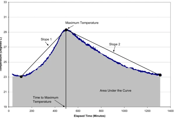
Figure 2. Variables slope 1, slope 2, maximum temperature, time to maximum temperature, and area under the curve...30
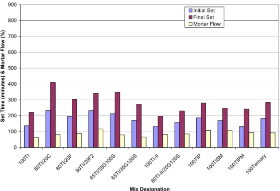
Figure 3. Set time and mortar flow for all control mixtures ...41
Figure 4. Relationship between specific surface and spacing factor for all mixtures ...43
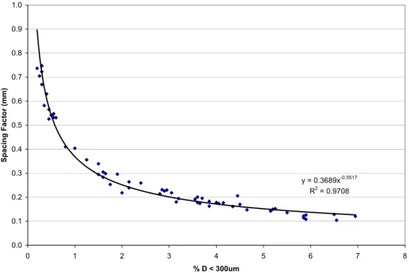
Figure 5. Relationship between spacing factor and % D < 300 µm for all mixtures...44
Figure 6. Relationship between specific surface and % D < 300 µm for all mixtures ...44
Figure 7. Effect of spacing factor on the average compressive strength for all mixtures ...45
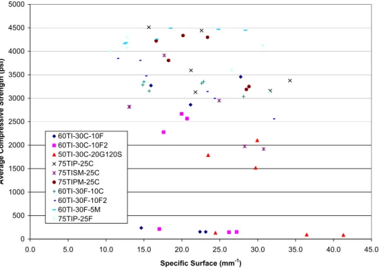
Figure 8. Effect of specific surface on the average compressive strength for all mixtures ...46
Figure 9. Effect of % D < 300 µm on the average compressive strength for all mixtures ...46
Figure 10. Effect of admixture combination on the spacing factor for mixtures containing large amounts of Class C fly ash...47
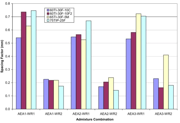
Figure 11. Effect of admixture combination on the spacing factor for mixtures containing large amounts of Class F fly ash ...48
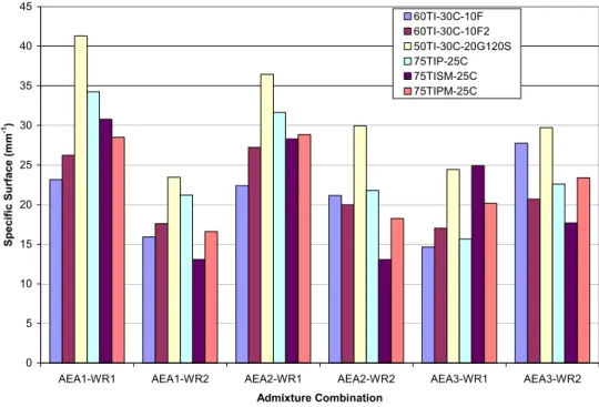
Figure 12. Effect of admixture combination on the specific surface for mixtures containing large amounts of Class C fly ash...49
Figure 13. Effect of admixture combination on the specific surface for mixtures containing large amounts of Class F fly ash ...49
Figure 14. Effect of admixture combination on the percent of air voids less than 300 μm for mixtures containing large amounts of Class C fly ash...50
Figure 15. Effect of admixture combination on the percent of air voids less than 300 μm for mixtures containing large amounts of Class F fly ash ...51
Figure 16. Effect of admixture combination on the average compressive strength for mixtures containing large amounts of Class C fly ash...52
Figure 17. Effect of admixture combination on the average compressive strength for mixtures containing large amounts of Class F fly ash ...52
Figure B-1. XRD results for Type I PC ...87
Figure B-2. XRD results for Type I/II PC ...88
Figure B-3. XRD results for Type ISM PC ...89
Figure B-4. XRD results for Type IPM PC ...90
Figure B-5. XRD results for Type IP PC...91
Figure B-6. XRD results for ternary cement...92
Figure B-7. XRD results for Class C fly ash ...93
Figure B-8. XRD results for Cayuga Class F fly ash...94
Figure B-9. XRD results for Coal Creek Class F fly ash...95
Figure B-10. XRD results for Grade 100 GGBFS...96
Figure B-11. XRD results for Grade 120 GGBFS...97
Figure B-12. XRD results for metakaolin...98
Figure B-13. XRD results for silica fume...99
Figure C-1. Heat signature for control mixtures containing Type I PC ...101
Figure C-2. Heat signature for control mixtures...101
Figure C-3. Heat signature for mixtures containing Type I PC and 20% Class C FA ...102
Figure C-4. Heat signature for mixtures containing Type I PC and 20% Class F1 FA...102
Figure C-7. Heat signature for mixtures containing Type I PC and 30% Class F1 FA...104
Figure C-8. Heat signature for mixtures containing Type I PC and 30% Class F2 FA...104
Figure C-9. Heat signature for mixtures containing Type I PC and 35% Grade 100 GGBFS ....105
Figure C-10. Heat signature for mixtures containing Type I PC and 35% Grade 120 GGBFS ..105
Figure C-11. Heat signature for mixtures containing Type I/II PC and Grade 120 GGBFS...106
Figure C-12. Heat signature for mixtures containing Type I/II PC ...106
Figure C-13. Heat signature for mixtures containing greater than 80% Type IP PC ...107
Figure C-14. Heat signature for mixtures containing Type IP PC...107
Figure C-15. Heat signature for mixes containing greater than 80% Type ISM PC ...108
Figure C-16. Heat signature for mixtures containing Type ISM PC ...108
Figure C-17. Heat signature for mixtures containing greater than 80% Type IPM PC...109
Figure C-18. Heat signature for mixtures containing Type IPM PC ...109
Figure D-1. Set time and mortar flow for mixtures containing Type I PC and 20% FA...111
Figure D-2. Set time and mortar flow for mixtures containing Type I PC and 30% FA...111
Figure D-3. Set time and mortar flow for mixtures containing Type I PC and 35% GGBFS or Type I PC and 5% metakaolin ...112
Figure D-4. Set time and mortar flow for mixtures containing Type I/II PC ...112
Figure D-5. Set time and mortar flow for mixtures containing Type IP PC...113
Figure D-6. Set time and mortar flow for mixtures containing Type ISM PC ...113
Figure D-7. Set time and mortar flow for mixtures containing Type IPM PC ...114
Figure E-1. Strength gain for control mortar mixtures ...115
Figure E-2. Strength gain for mortar mixtures containing Class C fly ash ...116
Figure E-3. Strength gain for mortar mixtures containing Class F fly ash...116
Figure E-4. Strength gain for mortar mixtures containing Class F2 fly ash...117
Figure E-5. Strength gain for mortar mixtures containing Grade 100 GGBFS...117
Figure E-6. Strength gain for mortar mixtures containing Grade 120 GGBFS...118
Figure E-7. Strength gain for mortar mixtures containing silica fume...118
Figure E-8. Strength gain for mortar mixtures containing metakaolin...119
LIST OF TABLES Table 1. ASTM C 618 chemical requirements for Class F and Class C fly ash...6
Table 2. XRF results for all cements used in Phase I ...17
Table 3. XRF results for all fly ashes with ASTM C 618 requirements...18
Table 4. XRF results for Grade 100 and 120 GGBFS with ASTM C 989 requirements ...18
Table 5. XRF results for metakaolin with ASTM C 618 requirements...19
Table 6. XRF results for silica fume with ASTM C 1240 requirements ...19
Table 7. Material identification ...22
Table 8. Control Mixtures for Phase I ...23
Table 9. Mixtures containing Type I PC and 20% Class C or F fly ash...23
Table 10. Mixtures containing Type I PC and 30% Class C or F fly ash...24
Table 12. Mixtures containing Type I/II PC...25
Table 13. Mixtures containing Type IP PC ...25
Table 16. Pozzolanic index test results for all SCMs ...28
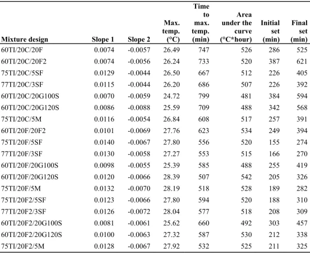
Table 17. Characterization results for the control mixtures ...30
Table 18. Characterization results for mixtures containing Type I PC and 20% FA ...31
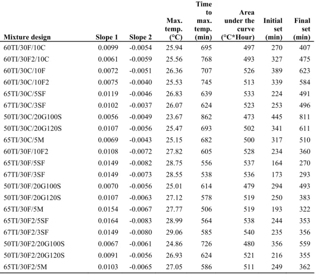
Table 19. Characterization results for mixtures containing Type I PC and 30% FA ...32
Table 20. Characterization results for mixtures containing Type I PC and 35% GGBFS or Type I PC and metakaolin ...33
Table 21. Characterization results for mixtures containing Type I/II PC...33
Table 22. Characterization results for mixtures containing Type IP PC ...34
Table 23. Characterization results for mixtures containing Type ISM PC...35
Table 24. Characterization results for mixtures containing Type IPM PC...36
Table 25. Variable and units used in models ...37
Table 26. Least squares regression analysis results...37
Table 27. Stepwise regression analysis results ...38
Table 28. Incompatibility set time results...42
Table 29. AEA and water reducer dosage rates...43
Table 30. Compressive strength results for the control mixtures ...53
Table 31. Compressive strength results for mixtures containing Class C fly ash ...54
Table 32. Compressive strength results for mixtures containing Class F fly ash...55
Table 33. Compressive strength results for mixtures containing Class F2 fly ash...56
Table 34. Compressive strength results for mixtures containing Grade 100 GGBFS...57
Table 35. Compressive strength results for mixtures containing Grade 120 GGBFS...58
Table 36. Compressive strength results for mixtures containing silica fume...59
Table 37. Compressive strength results for mixtures containing metakaolin...60
Table 38. Mortar mixtures over the recommended water reducer dosage rate...64
Table 39. Mortar mixtures following the recommended water reducer dosage rate ...64
Table 40. Mortar mixtures containing ternary cementitious materials with early retarded strengths following the recommended water reducer dosage rate...65
Table 41. Linear least squares regression analysis results for three- seven- and 28-day compressive strengths ...65
Table 42. Stepwise regression analysis results for three- seven- and 28-day compressive strengths ...65
Table 43. Paste content and shrinkage (as a percent of the control) for mortar mixtures containing Type I PC ...68
Table 44. Paste content and shrinkage (as a percent of the control) for mortar mixtures containing Type I PC (cont.)...69
Table 45. Paste content and shrinkage (as a percent of the control) for mortar mixtures containing Type I/II PC ...70
Table 46. Paste content and shrinkage (as a percent of the control) for mortar mixtures containing Type ISM PC ...70
Table 47. Paste content and shrinkage (as a percent of the control) for mortar mixtures containing Type IP PC...71
Table 48. Paste content and shrinkage (as a percent of the control) for mortar mixtures containing Type IPM PC ...71
Table A-1. CaO, SiO2, and Al2O3 properties of each mixture...83
Table F-1. Shrinkage for control mixtures...121
Table F-5. Shrinkage for mortar mixtures containing Grade 100 GGBFS...125
Table F-6. Shrinkage for mortar mixtures containing Grade 120 GGBFS...126
Table F-7. Shrinkage for mortar mixtures containing silica fume...127
ACKNOWLEDGMENTS
This research was conducted under Federal Highway Administration Pooled Fund Study TPF-5(117), involving the following State Departments of Transportation:
• California Department of Transportation • Illinois Department of Transportation
• Iowa Department of Transportation (lead state) • Kansas Department of Transportation
• Mississippi Department of Transportation • New Hampshire Department of Transportation • Pennsylvania Department of Transportation • Wisconsin Department of Transportation • Utah Department of Transportation
The researchers recognize the following partners for sponsoring this research: • American Coal Ash Association
• Headwaters Resources
• Portland Cement Association • Slag Cement Association
Finally, the researchers recognize the following companies for their in-kind contributions to this research: • BASF Admixtures • Elkem • Engelhard • Geneva Rock • Giant Cement • Holcim Cement • Keystone Cement • Lafarge Cement
EXECUTIVE SUMMARY
Supplementary cementitious materials (SCMs) such as fly ash, ground granulated blast-furnace slag (GGBFS), calcined kaolinite, natural pozzolans, and silica fume, have become common parts of modern concrete practice (PCA 2002; Transportation Research Board 1990). The blending of two or three cementitious materials to optimize durability, strength, or economics provides owners, engineers, materials suppliers, and contractors with substantial advantages over mixtures containing only portland cement (PC). However, these advances in concrete technology and engineering have not been adequately captured in the specification of concrete. Usage is often curtailed because of prescriptive concerns or historical comparisons about how such materials should perform. In addition, SCMs can exhibit significant variation in chemical and physical properties, both within a given source and, more commonly, between sources. Hence, current literature contains contradictory reports concerning the “optimal use” of SCMs. Users need specific guidance to assist them in defining the performance requirements for a concrete application and the selection of optimal proportions of the cementitious materials needed to produce the required durable concrete. The selection process is complicated by the fact that blended cements are currently available in selected regions (ACI 2007). Both portland and blended cements have already been optimized by the manufacturer to provide specific properties (i.e., setting time, shrinkage, strength gain). The addition of SCMs (as binary, ternary, or even more complex mixtures) can alter these properties, and hence, has the potential to impact the overall performance of the concrete.
The project presented herein provides the quantitative information needed to make sound engineering judgments pertaining to the selection and use of SCMs in conjunction with portland or blended cement. This report summarizes the results of Phase I of a three-phase project. The initial phase focused on the paste and mortar properties of 114 ternary mixtures. The results quantify the shrinkage, sulfate resistance, alkali silica reaction (ASR) mitigation, strength development, chemical and physical properties of SCMs, heat signature, and sensitivity to sucrose-based water-reducing admixtures. The result of this work was the identification of 48 cementitious combinations for use in Phase II of the project.
INTRODUCTION
SCMs, such as fly ash, GGBFS, natural pozzolans, calcined kaolinite, and silica fume have become common parts of modern concrete practice (PCA 2002; Transportation Research Board 1990; ACI 2007). The blending of two or three cementitious materials to optimize durability, strength, or economics provides owners, engineers, materials suppliers, and contractors with substantial advantages over mixtures containing only PC. However, these advances in concrete technology and engineering have not been adequately captured in the specifications for concrete. Usage is often curtailed because of prescriptive concerns or historical comparisons about how such materials should perform. In addition, SCMs can exhibit significant variability in chemical and physical properties, both within a given source and, more commonly, between sources. Hence, current literature contains contradictory reports concerning the “optimal use” of SCMs. Users need specific guidance to assist them in defining the performance requirements for a concrete application and the selection of optimal proportions of the cementitious materials needed to produce the required durable concrete. The selection process is complicated by the fact that blended cements are currently available in selected regions. Both portland and blended cements have already been optimized by the manufacturer to provide specific properties (i.e., setting time, shrinkage, strength gain). The addition of SCMs (as binary, ternary, or even more complex mixtures) can alter these properties, and, hence, has the potential to impact the overall performance of concrete. Research is needed to identify and quantify the major factors that govern the performance of mixtures containing multiple SCMs. The focus of the research should be directed at providing tools so users can increase the probability that these various materials will always have a positive impact on the overall durability of the concrete.
Project Goals
The goal of this project is to provide the quantitative information needed to make sound
engineering judgments pertaining to the selection and use of SCMs in conjunction with portland or blended cement. This information will lead to a more effective utilization of supplementary materials and/or blended cements enhancing the life-cycle performance and cost of
transportation pavements and structures. The efforts of this project will be directed at producing test results that support the following specific goals:
• Provide quantitative guidance for ternary mixtures that can be used to enhance the performance of structural and pavement concrete
• Provide a solution to the cold weather issues that are currently restricting the use of blended cements and/or SCMs
• Identify how to best use ternary mixes when rapid strength gain is needed • Develop performance-based specifications for concrete used in transportation
pavements and structures
Background
of the Resource Conservation and Recovery Act in 1986. The Texas DOT was one of the few DOTs that conducted work to optimize the use of fly ash or slag cement to produce concrete mixtures that meet specific performance objectives prior to 1990 (Tikalsky et al. 1988). For many years most states implemented a strategy that was meant to produce concrete mixtures that exhibit performance similar to mixtures employing only PC. With the growing availability of slag cement and silica fume, and the limited supply of high quality fly ash in some markets, the selection of materials for any given job has become more complicated.
SCMs have the potential to dramatically improve the overall performance of concrete by
increasing the longevity of the transportation infrastructure and decreasing the life-cycle cost of that infrastructure. However, the introduction of fly ash, silica fume, or slag cement has
periodically resulted in the following technical issues: • Rapid slump loss
• Unstable air content or inability to retain air • Uncontrolled cracking with late season paving • Overpasted or sticky mixtures
• Inability to predict workability and set time in early or late season construction • Scaling in mixtures containing high dosages of SCMs
Closer inspection of the list and the technical literature suggests that the root issues appear to be related to selection of material combinations, proportioning of cementitious materials,
constructability, ambient weather problems, and materials variability problems. However, some detailed discussion with appropriate materials vendors is needed to clarify the reasons for the real or perceived problems and to design solutions that optimize multiple cementitious systems for transportation concrete.
There are currently several ongoing research projects in this area. The Pennsylvania DOT and an industrial consortium have been working with Pennsylvania State University on optimizing performance in bridge deck concrete, using both binary and ternary blends of SCM (Tikalsky et al. 2003). The Texas DOT has conducted detailed studies on optimizing fly ash and PC
combinations for selected performance characteristics (Carrasquillo et al. 1986). On a national level, the Federal Highway Administration (FHWA) initiated a major project (Task 64) that will help simplify job-specific mixture design when multiple sources of materials are available. The National Cooperative Highway Research Program (NCHRP) has two projects that are currently in progress that deal with SCMs. The first project is entitled “Supplementary Cementitious Materials to Enhance Durability of Concrete Bridge Decks (Project 18-08A).” The second project is entitled “Improved Specifications and Protocols for Acceptance Tests on Processing Additions in Cement Manufacturing (Project 18-11).”
Outline of Study Phases
Phase I of this study consisted of laboratory experiments that examined the influence of multiple combinations and proportions of cement, slag, silica fume, calcined kaolinite, and fly ash on
range of different materials and many different dosage levels. Test results were evaluated to identify material combinations for potential optimums in the various performance responses. Chemical admixtures (water reducers, air-entraining agents, and accelerators) were included in this phase of the study to compare how setting time, water demand, and air content vary with ternary mixtures. Phase I results were used to help create the architecture for predicting the performance of ternary systems based on the material properties of the total cementitious system. All of the materials used in the study were subjected to bulk chemical and physical testing in accordance with the appropriate American Society for Testing and Materials (ASTM) or
American Association of State Highway and Transportation Officials (AASHTO) specifications. In addition, X-ray diffraction (XRD) was used to determine the minerals present in the bulk samples and selected paste specimens. Glass content of the various SCMs and blended cements was estimated using semi-quantitative XRD analysis.
Phase II of the study will use the information obtained from Phase I to select a range of materials and dosages to investigate the effects of cold, hot, and ambient environmental conditions for use in laboratory concrete mixtures. The thrust of Phase II is to apply the mortar study data from Phase I to concrete mixtures and the performance characteristics of pavement and structural concrete. The materials used in both phases will be identical so that the mortar test results can be directly compared to the test results obtained from concrete test specimens. This comparison is needed to provide information pertaining to the selection of appropriate mixture design and performance tests for specification development. It would be desirable to develop mixture design tests using the behavior of mortar specimens that translate well into the performance of concrete. The results of Phase II will be trial performance-based specifications for concrete in
transportation applications.
Phase III will be a field demonstration phase where contractors and states will have on-site technical support for using ternary mixtures. After each trial, the performance-based specifications will be reviewed and revised if necessary. The National Concrete Pavement Technology Center’s (CP Tech Center) mobile research laboratory will participate in at least one project for each participant state.
LITERATURE REVIEW
Concrete is the world’s most used and versatile construction material. Modern concrete is
composed of six main ingredients: (1) coarse aggregate, (2) sand, (3) PC, (4) SCMs, (5) chemical admixtures, and (6) water.
Lime-based cements have been used for concretes as early as 7000 BC. Natural cements have been manufactured in the US since the early 1800s with the first being in Rosendale, NY. The first use of portland cement concrete (PCC) in the United States was in the Erie Canal in 1818. Pozzolans have been in use for thousands of years and excellent historical summaries are readily available in the literature (Abdun-Nur 1961; Mielenz 1983; Helmuth 1987; Lea 1971; Massazza 1998).
With the current global demand for PC sustainability on the rise, combined with a need for long life pavements and structures, engineers have looked to alternative binders such as fly ash, silica fume, GGBFS, metakaolin, and rice husk ash to increase pavement durability while lowering life-cycle cost.
Cementitious Materials
The cementitious materials section of the literature review provides a brief background on the materials used in this study including: PC, Class C and Class F fly ash, GGBFS, silica fume, and metakaolin.
Portland Cement
PC is manufactured using several key ingredients including limestone, clay or shale, and
gypsum. Limestone provides the necessary calcium oxide while clays and shale provide the iron-bearing aluminosilicates. The materials are pulverized and heated to 1400°C to produce the calcium silicates characteristic of PC. The finished product, clinker, is then ground in ball mills, with added gypsum to prevent false set, and stored in silos until ready for distribution (Lea 1971). ASTM C 150, C 595, and C 1157 specify the chemical and physical requirements of the different types of PCs in the United States.
Ground Granulated Blast Furnace Slag
GGBFS is a predominately glassy material from the iron metal industry and is produced in iron blast furnaces at a temperature of about 1500°C. The molten slag is granulated by rapidly
quenching it as it is drawn off the metal. Then the granulated material is ground to a fine particle size prior to being incorporated in mortar or concrete with other hydraulic cements or
appropriate activators. Slag is not a basic pozzolan; rather it is cementitious material with both cementitious and pozzolanic properties. The cementitious nature of the GGBFS is much less rapid than that exhibited by PC. GGBFS has been used as a SCM since the early 1900s (Tuthill
1978; Lea 1971). However, it is only during recent years that the material has become widely available nationally. In 2006, approximately 3.5 million tons of GGBFS were sold in the US. The ASTM specification for GGBFS is C 989 (ASTM 2007). The specification classifies GGBFS into three grades of 80, 100, and 120, based on compressive strength of mortar cubes (slag activity index test). The increasing grades correspond to increasing levels of reactivity or a more rapid strength gain in the slag activity index test. Practical information concerning the use of GGBFS can be found in ACI 233R-95 (ACI 2007). Slag can be used to replace PC in many different mix designs including pavements, structural concrete, and bridge decks. The slag replacement level can vary significantly from about 20% to 60% in some cases. The lower replacement range is typically used when setting time or hardening constraints limit the mix design. Higher replacement rates are generally used when ASR or sulfate resistance is required.
Fly Ash
Fly ash is the most commonly used SCM. Fly ash is the residue collected from the flue gasses exiting the boiler of a pulverized coal-generating station. The fly ash particles are collected in electrostatic precipitators or bag houses and then transferred to a storage silo or sluice pond. Fly ash has a spherical morphology and exhibits a rather wide range of bulk chemical compositions. This wide range of chemical composition has resulted in the creation of two classes of fly ash in ASTM specifications (ASTM 2007), and three classes of fly ash in Canadian Standard
Association (CSA) (CSA 1998).
The majority of electricity produced in the United States is produced from the combustion of coal at coal-fired utilities. As a result, over 117 million tons of coal combustion byproducts are produced per year (American Coal Ash Association 2003). The American Coal Ash Association (ACAA) (2003) estimates that 68 million tons of fly ash are produced in the U.S. per annum. The 68 million tons are broken down into the following categories and tonnages (ACAA 2003):
• Bottom ash is approximately 18.7 million tons. • Boiler slag totals approximately 2.5 million tons.
• Other byproducts are approximated at 24.8 million tons.
ASTM Specifications break fly ash into two classes based on SiO2+Al2O3+Fe2O3 content. Class F fly ash has a SiO2+Al2O3+Fe2O3 of 70% or more. Class C fly ash has a SiO2+Al2O3+Fe2O3 content between 50% and 70%. Class F ashes are typically pozzolanic; however, some authors have noted that they may occasionally exhibit some self-cementitious properties (Majko 1987). Class C fly ashes may exhibit self-cementitious properties (ASTM 2007); however, some authors have expressed concern that this is an oversimplification (Cain 1981; Diamond 1981).
CSA specifications break fly ash into three types based on bulk calcium content (expressed as the oxide CaO). Type F has less than 8% bulk CaO. Type CI fly ash has a CaO content from 8% to 20%. Type CH fly ash has a bulk CaO content greater than 20%. This categorization scheme was created to deal with the fact that many high-calcium fly ashes were not producing some of
attack (Dikeou 1975; Dunstan 1980; Tikalsky et al. 1992) and reduction in expansion caused by alkali-silica reaction (ASR) (Manz 1998; Shehata 2002).
Chemical and Physical Properties of Fly Ash
ASTM C618 defines fly ash as the fine residue produced from the burning of ground or powdered coal. Fly ash is collected from the flue gas of coal-fired boilers by the means of an electrostatic precipitator or bag house. Fly ash color may vary from tan to gray (Misra 2000). Self-cementing, Class C fly ash is generally produced from burning low sulfur, subbituminous and lignite coals. Class F fly ash is generally produced from burning bituminous and anthracite coals.
Fly ash particles are typically spherical in nature and contain some crystalline as well as carbonaceous matter (Barnes 1997; Misra 2000). Misra (2000) noted that a large percentage of fly ash is in the form of silica, alumina, ferric oxide, and calcium oxide. ASTM C618 chemical requirements are shown in Table 1.
Barnes (1997) and Misra (2000) state that the pozzolinity of fly ash is mainly dependent upon the fineness of the ash, amounts of silica and alumina, and the presence of moisture and free lime. Winkerton and Pamukcu (1991) also state that density, amount of carbon, temperature, and age also affect the rate of pozzolanic reaction.
Table 1. ASTM C 618 chemical requirements for Class F and Class C fly ash
Oxide Class C fly ash ASTM C 618 Class F fly ash ASTM C 618
SiO2 Al2O2 FeO3 Summation between 50% and 70% Summation greater than 70% CaO MgO Na2O K2O TiO2 SO3 Maximum of 5% Maximum of 5%
previously mentioned. Typically, the minerals identified in a sample of fly ash give a good indication of the pozzolanic or cementitious nature of the fly ash. Class F (or Type F) fly ashes contain a silicate glass and only a few minerals (alpha-quartz, mullite, a ferrite spinel, and perhaps small amounts of anhydrite and free lime). This glass is relatively insoluble in hydrochloric acid (less than 15% soluble). Class C fly ashes can contain a wide variety of minerals (McCarthy et al. 1984; McCarthy et al. 1990), and several of the minerals hydrate rapidly when mixed with water. This helps explain their self-cementitious behavior. Class C fly ashes tend to be quite soluble in hydrochloric acid (about 70% soluble), and most of the soluble material is related to both the cementitious materials and a high-calcium glass phase. Also, Class C fly ash contains a pozzolanic glass similar to Class F fly ash. Hence, both the mineralogy and bulk chemistry of Class C fly ash tends to be much more complex than that observed for Class F fly ash.
Practical information concerning the use of fly ash can be found in ACI 232.2R-96 (ACI 2007). Other similar sources of information exist (FHWA 1995). Most common mix design procedures rely on strength as the desired output (Kosmatka, Kerkhoff and Panarese 2002). However, as is fully described in the American Concrete Institute (ACI) document, strength does not need to be the primary criterion. Often, one may choose to improve sulfate resistance or minimize
expansion caused by ASR. Fly ash replacements vary widely depending on the needs of any given project. Most concrete mixtures formulated for pavements tend to use approximately 15% to 30% fly ash as a cement replacement (ACI 2007; Hanson 2003; Parry 2001). The upper limit appears to be related to scaling issues noted in laboratory research (Parry 2001) but not generally observed in the field. Hence, such constraints may not be critical to states with less severe
exposure conditions.
Silica Fume
Silica fume is a byproduct production of the silicon or ferrosilicon metal (Malhotra, 1987; Fidjestol and Lewis 1998). The material may also be referred to as condensed silica fume or microsilica. Particles of silica fume are collected in the bag house exiting a submerged-arc furnace. Hence, silica fume is almost entirely composed of sub-micron sized particles of amorphous silica. The material has both ASTM (ASTM 2007) and CSA (Canadian Standards Association 1998) specifications that describe the tests and specification limits applicable to the material. Silica fume is probably the most expensive of the SCMs that are used in the study; hence, it is available throughout most of the US. Experts in the industry (Wolsiefer 1999) indicate that about 75,000–100,000 tons of silica fume are produced in the US and Canada each year. The production depends heavily on the demand for silicon metal and the number of furnaces that are operational.
Current ASTM C1240 and CSA specifications indicate that the bulk of SiO2 in the material must be at least 85%. However, there are alloys that do not meet this criterion, and there is still
considerable debate on the use of these “non-spec” materials. Silica fume behaves as a pozzolan when mixed with calcium hydroxide or PC. Hence, the chemical reactions that take place when silica fume is mixed with cement (or lime) are reasonably well-understood. The main issues of interest to concrete technology are its tremendous surface area (which requires the use of
high-material. Both of these properties may cause air-entrainment issues in concrete. Practical information concerning the use of silica fume can be found in ACI 234R-96 (ACI 2007). Silica fume is typically used at quantities between 3% and 8% of the total cementitious materials in high-performance concrete, while a common range for pavement concrete is about 3% to 5%.
Metakaolin
Metakaolin, a calcined kaolinite clay mineral, is a processed pozzolan that can be combined with calcium hydroxide in solution to form calcium silica hydrate. The modern use of metakaolin dates back to 1962 when it was used to supplement PC during construction of the Jupia Dam in Brazil (Pera 2001). During heating, adsorbed water is driven off at 100°C, and the kaolinite decomposes at about 500°C. At 500°C, the hydroxyl groups are lost in the form of water. At temperatures of greater than 900°C, the metakaolin undergoes further reactions forming crystalline compounds of free silica and mullite (Pera 2001; Sabir et al. 2001).
Metakaolin is generally used to enhance concrete properties (Potgieter-Vermaak and Potgieter 2006). Concrete property improvements include the following: increased compressive strength, improved sulfate resistance, suppressed ASR expansion (Ramlochan et al. 2000), and reduced permeability. Through research, Frias and others (2000) noted increased heat of hydration when incorporating metakaolin. The researchers noted that heat of hydration curves for metakaolin concrete can be obtained to closely match heat of hydration curves for PCC when the metakaolin is incorporated at amounts less than 10% by weight.
The use of metakaolin in concrete tends to increase the water demand requiring a larger dosage of water-reducing admixture (Zhang and Malhotra 1995; Sabir et al. 2001). Zhang and Malhotra (1995) also noted an increased demand for air-entraining admixture comparable to a silica fume concrete. Metakaolin is beneficial in reducing drying shrinkage when compared to silica fume concrete.
Optimum ranges for metakaolin addition depend upon desired properties. Research conducted by Vu et al. (2001) noted the optimum to be 15% to 25% for compressive strength. Ramlochan et al. (2000) noted that 15% replacement is sufficient to prevent deleterious ASR expansion.
Admixtures
Admixtures are defined in ASTM C 125 as ingredients used in concrete other than materials such as water, aggregates, cement, and fiber reinforcement (Mindess et al. 2003). Such admixtures provide benefits by reducing cost, achieving sought properties, and helping to maintain quality concrete. More extensive classifications of each admixture can be found in various ASTM specifications (Kosmatka et al. 2002).
agent stabilizes small air bubbles (0.002 to 0.05 inches in size) in concrete to help protect against damage induced by expansion of freezing pore water. Satisfactory frost protection can generally be obtained with an air content range of 4% to 8% by volume of concrete (Mindess et al. 2003). Air-entraining admixtures consist of salts of wood resins (Vinsol resin), synthetic detergents, salts of sulfonated lignin, salts of petroleum acids, salts of proteinaceous material, fatty and resinous acids and their salts, alkylbenzene sulfonates, and salts of sulfonated hydrocarbons. These admixtures are defined in ASTM C 260 and AASHTO M 154.
Water Reducers
Water reducers lower the amount of water required to attain a given slump, or simply reduce the water demand (Mindess et al. 2003). Therefore, the use of this admixture can reduce the water-cement ratio which will essentially increase the strength but can also increase the drying shrinkage (Kosmatka et al. 2002).
There are three broad classifications for water reducers used by manufacturers: low-range, mid-range, and high-range. The regular or low-range water reducer can reduce the water content by approximately 5% to 8%, while the mid- and high-range water reducers have higher percentages of reduction. Materials for water-reducing admixtures can consist of lignosulfonates, melamines, hydroxylated carboxylic acids, or carbohydrates. Performance specifications for regular water reducers can be found in ASTM C 494.
Roberts and Taylor (2007), Sandberg and Roberts (2005), and Wang et al. (2006) have studied some interaction issues with the combined use of PC, SCMs, and admixtures. They suggest these problems are associated with low system sulfate contents which are insufficient to control
aluminate reactions, which, at the same time, are accelerated by some water-reducing admixtures.
In depth, Roberts and Taylor (2007) indicate that high-calcium fly ashes may contain calcium aluminates, which require additional sulfates to control their reactions. Sandberg and Roberts (2005) also describe SCMs as having larger surface areas due to their fineness, which also effectively increases the amount of sulfate required. Sandberg and Roberts (2005) noted that increasing the rate of hydration requires a greater amount of soluble calcium sulfate to control the aluminate hydration. Roberts and Taylor (2007), Sandberg and Roberts (2005), and Wang et al. (2006) each conclude that the combined use of SCMs and admixtures can severely delay strength development within a concrete mixture.
Roberts and Taylor (2007) and Sandberg and Roberts (2005) compared the heat flow versus time for a plain Type I cement, a mix with 68% cement and 32% Class C fly ash, and the same binary mixture with 325mL/100kg cementitious Type A water reducer. These graphs were drawn to show silicate hydration which is the second peak in the heat flow versus time graph. The cement alone hydrated normally with the silicate hydration peak of 3.0 mW/g at eight hours. When the Class C fly ash was added there was a reduction in silicate hydration heat with a second peak of
1.25 mW/g at 12 hours. No visible silicate reaction was seen in the binary mixture with the Type A water reducer.
Wang et al. (2006) also looked at cement hydration for a Type I cement, a Type I cement and 20% Class F fly ash with 2.6mL/kg Type A water reducer and Type B retarder, and a Type I cement and 20% Class C fly ash with 0.04 oz./lb (2.6 mL/kg) Type A water reducer and Type B retarder. Each chemical was added on a cement mass basis and a cementitious mass basis. The plain Type I cement silicate hydration peak occurred around 5 mW/g at eight hours. The Class F fly ash peak with the chemicals added by a cement mass base occurred later with an energy release rate of 4 mW/g at 14 hours. The Class F fly ash with the admixtures added by a
cementitious mass base had a lower peak with 3.25 mW/g at 17 ½ hours. The total hydration of heat for the mixture containing the Class C fly ash was significantly depressed compared to the other mixtures. The peak based on the cement mass had an energy release rate of 3.5mW/g at 17 hours while the peak based on the cementitious mass had a rate of 3 mW/g at 21 hours.
Roberts and Taylor (2007), Sandberg and Roberts (2005), and Wang et al. (2006) each suggest it is important for the producer of the mixture to stay within the recommended limits of admixture dosage rates. Roberts and Taylor (2007) describe doubling or even tripling a recommended dosage has been found to delay the silicate peak causing retardation. Dosages of mixtures combining SCMs and admixtures should be limited and may need to be reduced to avoid early strength development problems.
Engineering Properties
The engineering properties section of the literature review is composed of four main parts dealing with the effect of SCMs on workability, heat of hydration, durability, and strength development.
Workability
Fresh concrete properties are important to a contractor for ease of placement and finishing. It is important to ensure proper air entrainment, as well as the desired workability to achieve a durable concrete.
The use of certain SCMs has been found to enhance the workability properties of PCC through synergy. Kashima et al. (1992) noted that the use of high contents of slag and fly ash allowed for the longer flow distances and the longer retention in flowability required for underwater bridge footings. In a study where workability was a secondary variable, the mixtures containing fly ash and GGBFS were shown to have improved workability when compared to mixtures containing silica fume (Swamy and Laiw 1995).
In a study completed by Collepardi et al. (2000), material fineness and its effect on the workability of concrete was studied. The results showed that an increase in the cementitious materials’ fineness required an increase in superplasticizer to achieve the desired workability.
The round fly ash particles are reported to have a plasticizing effect on concrete rheology. Results obtained by Bhanumathidas and Kumar Mehta (2001) note that for mixtures produced with 50% total replacement, 40% fly ash, and 10% rice husk ash, increasing the fly ash content produced a more workable concrete. Results also showed that bleeding was reduced significantly when rice husk ash was introduced.
Heat of Hydration
Through the course of cement hydration, a significant amount of heat is produced. The heat produced causes thermal expansion and subsequent contraction with cooling of the concrete structure, potentially leading to thermal cracking. Thermal cracking is an issue that is encountered most when dealing with large concrete mass structures.
Addition of SCMs, such as GGBFS and fly ash, lowers the heat generated during hydration, thus reducing the potential for thermal cracking. Kashima and others (1992) noted that ternary
blended cement with GGBFS and fly ash adequately produced a concrete with a low adiabatic temperature rise of 47.9°C—about a 75% reduction when compared to a normal PCC mixture. The Fancuo Hydropower Station located in China incorporated both fly ash and silica fume. Fly ash was incorporated to lower the heat of hydration while the silica fume was added to increase abrasion resistance and strength. Both materials reduced concrete permeability. Results showed a 25% fly ash replacement rate increased the setting time and greatly lowered the heat of hydration (Baoyu et al. 1989).
Frias et al. (2000) noted the increased heat of hydration when incorporating metakaolin. They noted that heat of hydration curves for metakaolin concrete can be obtained to closely match heat of hydration curves for PCC when the metakaolin is incorporated at amounts less than 10% by weight.
Durability
Research has shown that the use of SCMs has several benefits to PCC directly affecting durability, including refined pore structure, lower permeability, and increased strength. The refined pore structure and reduced permeability are attributed to the pozzolanic reaction products formed, leading to a more dense paste structure found by Torii and Kawamura (1992). Some of the negative aspects of SCM replacement associated with durability include increased tendency for plastic and thermal shrinkage cracks, increased carbonation, and an increase in deicer scaling at early ages. In a study completed by Khatri and Sirivivatnanon (2001), the optimum fly ash content for chloride resistance durability in aggressive environments was determined to be about 40% replacement rate. The replacement rate dropped to 30% in mild chloride environments. While much literature is available noting the benefits of SCM replacement for a more durable concrete, it is important to note that other factors affect durability as well. Other factors affecting durability include: water to cementitious materials ratio (w/cm), mix proportions, construction
Talbot et al. (1995) note that the use of fly ash in high replacement rates can reduce resistance to deicer salt scaling, even with reduced water to cementitious materials ratios. Although Talbot et al. note decreased resistance to salt scaling when using high volume fly ash and GGBFS
replacements, they observed a reduction in capillary pore structure inferring a reduced
permeability. Results obtained by Bijen et al. (1989), and Papadakis (2000) showed carbonation rates proceeding quickly, but then slow rapidly due to a denser pore structure attributed to pozzolanic reactions.
Taylor et al. (1995) implemented a study to establish performance criteria for a smelter project in South Africa. Several mixes were produced over a range of w/cm and then subjected to
durability testing after a short curing period. Materials included Type I PC, Type III PC, GGBFS, Class F fly ash, and silica fume in the powder and slurry form. Durability testing included Autoclam air permeability and chloride conductivity. The test results showed that there is no difference in durability when comparing the two forms of silica fume; and poor curing of the GGBFS and fly ash mixtures produced poor air permeability results, showing that curing is of utmost importance. Chloride permeability results showed that the silica fume mixtures outperformed all other mixtures for the limited curing provided.
A study conducted by Swamy and Laiw (1995) showed that w/cm has an effect on chloride ion penetration depth. The authors also noted that the chloride concentration profile is essentially the same shape for all concrete mixtures. Chloride penetration depth was shown to be reduced for those concretes with fly ash, GGBFS, or silica fume. The results showed that the silica fume concrete showed the greatest reduction in chloride penetration depth followed by the GGBFS concrete and fly ash concrete respectively. Similar results were obtained by Torii et al. (1995) for a study including calcium chloride. Ganesh Babu and Sree Rama Kumar (2001) investigated the effects of GGBFS in aggressive marine environments. The results showed that to produce a concrete containing GGBFS resistant to the harsh chloride environment, a 50% replacement rate was needed.
Ramezanianpour et al. (1998) studied the performance of concretes with SCMs under cyclic wetting and drying. Using a constant w/cm of 0.4 and a superplasticizer to keep a medium
slump, several concrete mixtures were produced. SCMs included silica fume and GGBFS as well as diatomite and trass. Cyclic wetting and drying were used to simulate Persian Gulf conditions. Chloride and sulphate content were tested at four months to determine corrosion rates. The results showed that specimens subjected to the cyclic wetting and drying in sea water had higher chloride values; and the addition of SCMs improved the performance.
Environmental sulfate attack can damage concrete due to the formation of gypsum, ettringite, and thaumasite leading to spalling, strength reduction, and mass loss at low temperatures. Borsoi and others (2000) completed a study investigating the effects of a tricalcium aluminate-free PC with fly ash and GGBFS on thaumasite formation. The results showed that after five years of exposure to MgSO4, there appeared to be little to no surface damage. XRD analysis confirmed neither ettringite nor thaumasite were present near the concrete surface.
to form a ternary system. The results showed that incorporation of fly ash and silica fume decreased the chloride permeability gradually from 7 to 90 days. Silica fume was shown to be better than fly ash at reducing permeability at later ages. The results showed that the ternary blends reduced permeability at both early and later ages. The oxygen permeability results showed that fly ash had little effect, but silica fume had a significant effect on the reduction of oxygen permeability.
Ramlochan, Thomas, and Gruber (2000) noted increased durability of concrete incorporating metakaolin. Results showed 10% to 15% replacement of PC with metakaolin may be sufficient to control deleterious ASR expansion. Results showed reduction in ASR expansion occurred due to entrapment of alkalis by the supplementary hydrates and a decrease in the pH of the pore solutions.
Gruber et al. (2001) showed incorporation of metakaolin decreased chloride permeability of concrete. The level of reduction averaged 50% to 60% for mixes containing 8% and 12% metakaolin, respectively.
Strength Development
Strength development of PCC is affected by several factors, including mixture proportions, cement and admixture chemistry, temperature, and curing conditions. Giergiczny (1992) noted that elevated curing temperatures and pressures produced elevated strengths when compared to low pressure steam curing.
The use of SCMs can significantly affect the strength development of PCC. Generally, the use of SCMs tends to slightly decrease the early-age strengths and increase the long-term strengths, as is the case with fly ashes and GGBFS. Silica fume and metakaolin on the other hand tend to increase the strength of PCC at all ages.
Kelham et al. (1995) tested several pastes and mortars for compressive strength development. The results showed a reduction in strength when ground limestone was added about equal to the percentage of limestone added. The GGBFS was shown to increase strengths after seven days while the fly ash did not contribute to strength development until greater than 28 days. In a study undertaken by Collepardi et al. (2000) to establish the engineering properties of concrete containing combinations of Class F fly ash, silica fume in the powder form, and combinations of GGBFS and silica fume, compressive and flexural strength was measured. The testing results showed the fly ash-silica fume strengths lagged behind the GGBFS-silica fume strengths after one day. Swamy and Darwish (1998) noted that all fly ash–silica fume and GGBFS–silica fume samples attained the target strength of 40 MPa at seven days and 50 MPa at 28 days. The results also showed increase in flexural and compressive strength due to pozzolanic activity, except in those samples exposed to air. The authors noted that exposure to air caused cessation of pozzolanic activity.
Temperature plays an important factor in compressive strength gain, as shown in a study completed by Collepardi et al. (2000). Four concretes with up to 50% mass replacement of cement with fly ash and GGBFS were cured at 5°C and 20°C. The results showed higher strengths for those samples cured at 20°C. Strengths were found to increase slightly when incorporating ground fly ash when compared to normal fly ash and strengths improved more so when incorporating GGBFS.
A project completed in Olvarria, Argentina compared a normal PC to a limestone PC with a high activity GGBFS (Menedez et al. 2002). The limestone PC contained 18% ground limestone powder. The limestone powder is not a pozzolan, but provides nucleation sites for calcium hydroxide crystals. The limestone powder was used to improve early age strength while the GGBFS was used to improve long term strength. The results show addition of limestone powder and GGBFS improved the early and later age strengths. Addition of the GGBFS also increased slump retention providing a more workable concrete.
A study completed by Shiathas et al. (2003) compared the properties and durability of binary and ternary cementitious systems and found that metakaolin increased compressive strength rapidly and reduced chloride ion penetration. The results also showed GGBFS reduced early age strengths and exhibited higher permeability values at early ages, but showed later age values comparable to the control mixture of normal PC.
Literature points noted increased strengths when incorporating metakaolin as a mineral admixture (Zhang and Malhotra 1995; Wild et al. 1996; Curcio et al. 1998). Results showed faster compressive strength gain when compared to silica fume up to 28 days. Results obtained by Wild et al. (1996) showed an optimum replacement rate for metakaolin to be about 20% for long term strength gain.
METHODS
ASTM Standards
The following ASTM standards were used in determining the chemical characteristics of the cementitious materials and the physical characteristics of the sand used in this study:
• ASTM C 128 [Standard Test Method for Density, Relative Density (Specific Gravity), and Absorption of Fine Aggregate]
• ASTM C 150 [Standard Specification for Portland Cement]
• ASTM C 204 [Standard Test Method for Fineness of Hydraulic Cement by Air-Permeability Apparatus]
• ASTM C 311 [Standard Test Methods for Sampling and Testing Fly Ash or Natural Pozzolans for Use in Portland-Cement Concrete]
• ASTM C 595 [Standard Specification for Blended Hydraulic Cements]
• ASTM C 989 [Standard Specification for Ground Granulated Blast-Furnace Slag for Use in Concrete and Mortars]
• ASTM C 1240 [Standard Specification for Use of Silica Fume as a Mineral Admixture in Hydraulic Cement Concrete, Mortar, and Grout]
The following standards were used in the mixing and development of the performance properties of the ternary cementitious systems. Deviations from the standard are noted.
• ASTM C 109 / C 109M [Standard Test Method for Compressive Strength of Hydraulic Cement Mortars (Using 2-in. or [50-mm] Cube Specimens]
• ASTM C 157 / C 157M [Standard Test Method for Length Change of Hardened
Hydraulic-Cement Mortar and Concrete]
• ASTM C 185 [Standard Test Method for Air Content of Hydraulic Cement Mortar] *Deviated by using a non-standard sand gradation
• ASTM C 187 [Standard Test Method for Normal Consistency of Hydraulic Cement] • ASTM C 191 [Standard Test Method for Time of Setting of Hydraulic Cement by
Vicat Needle]
• ASTM C 305 [Standard Practice for Mechanical Mixing of Hydraulic Cement Paste and Mortars of Plastic Consistency]
• ASTM C 403 / C 403M [Standard Test Method for Time of Setting of Concrete Mixtures by Penetration Resistance]
• ASTM C 1012 [Standard Test Method for Length Change of Hydraulic-Cement
Mortars Exposed to a Sulfate Solution]
• ASTM C 1437 [Standard Test Method for Flow of Hydraulic Cement Mortar] • ASTM C 1567 [Standard Test Method for Determining the Potential Alkali-Silica
Reactivity of Combinations of Cementitious Materials and Aggregate (Accelerated Mortar-Bar Method
X-ray Diffraction (XRD) Testing Method
XRD was performed using a Bruker (SIEMENS) D 500 X-ray diffractometer. The instrument was configured with Bragg-Brentano geometry, 1° fixed divergence and 0.05° medium resolution detector slits, diffracted beam monochromater tuned to Cu K-alpha radiation, scintillation detector and a pulse-height analysis (PHA) circuit. The source operated at 27 kV / 50 mA and the target was a Cu fine focus with a 1.5kW maximum power side-window tube. The instrument consisted of a cavity mount specimen holder 25.4 mm diameter by 5 mm deep in dimensions. The sample was prepared as a power mount which was back-loaded on a frosted glass surface. Data results were collected by a step-scan mode which operated at 3 seconds / 0.05°2Θ. Jade 7.0 was used for analysis of the data.
XRF Testing Method
kW. XRF analyses ran at a constant power of 3600 watts while changing the kV (mA) settings to optimize excitation of the various elements.
Two sample preparation techniques were used for XRF analysis: fused disk and pressed pellets. PC, fly ash, and natural pozzolans were prepared using the fused disk technique. The fused disk technique consisted of combining a fixed amount of sample with lithium tetraborate and fusing the flux-sample mixture into a glass disk. Other SCMs such as GGBFS and silica fume used the pressed pellet technique due to the reduced amount of sulfur present in the samples. The pressed pellet technique consisted of using a fixed amount of sample with a binder made up of X-ray mix powder and boric acid, and then pressing the sample to construct a “pellet.”
SuperQ 3.0j was used for analysis of the data. Fundamental parameter (FP) calculations based on the Sherman equation were used to compensate for interelement effects, such as absorption and enhancement in the fused disks and pressed pellets, which are included in the Super Q software.
Air Void Analyzer (AVA) Testing Method
The AVA testing method followed is similar to the procedure recommended by the AASHTO AVA Technical Implementation Group (TIG) (2003) except for the sampling method. In lieu of a vibrating cage sampler, the research team hand-packed the syringes with prepared mortar. The AVA testing procedure involves placing water into the riser column. The bottom of the column is then filled with glycerol using a special funnel. The mortar sample is injected into the glycerol and a magnetic stir bar mixes the glycerol and mortar for 30 seconds. The air voids released during and after mixing are recorded on an inverted glass dish as a change in mass over time. The test can take up to 30 minutes to complete; and the software displays the cumulative distribution of air voids, a histogram of the air voids, and calculated values of spacing factor and specific surface.
Heat Generation
For determination of heat generated, the mortar was mixed as above and then transferred to 4 x 8 in. cylinders. A t-wire thermocouple was inserted to the center of the cylinder. The samples, usually eight, were placed into a curing chamber with an air temperature of 70°F ± 2°F and the temperature change was recorded every minute for about 24 hours. The data was then reduced using spreadsheet software.
Laser Particle Size Analysis
Particle size analyses are based on diffraction as particles pass through a laser beam. As the particles interact with the beam, light will scatter at different angles according to the particles’ size. For example, as particle size decreases, the scattering light angles will increase. Detectors measure the light pattern over several angles. The particle sizes are then calculated based on an
The Mie Theory is a common model used which predicts the scattering intensities for small and large, transparent and opaque particles. This theory describes the intensity predicted by the refractive index difference between particles and a dispersion medium (Kippax 2007).
Incompatibility
Incompatibility tests were conducted on 10 mix designs for determination of potential
compatibility issues regarding the air void system and set time characteristics. For the set time tests, ASTM C 191 was used. The proportion needed to obtain normal consistency was
determined for a mix containing 100% Type I PC. The same proportions (mass of water and cementitious material) were used for the 10 mixtures tested. Each mixture design was
investigated using MB VR Standard AEA (1.3 mL/kg) with a normal dose of Pozzolith 200N (2.3 mL/kg) and PS-1466 (2.6 mL/kg). The dosage rates of the water reducer were also doubled. For the determination of the air void structure, the 10 mixtures were produced using each
combination of water reducer and AEA producing six mixes for each one mixture, or 60 total mixtures. Dosage rates for the MB VR Standard, MB AE 90, and Microair were 1.3 mL/kg, 1.3 mL/kg, and 0.49 mL/kg, respectively. Dosage rates for the Pozzolith 200N and PS-1466 were 2.3 and 2.6 mL/kg, respectively. The AVA was then used to determine the air void structure on freshly mixed mortar.
MATERIALS
This section describes the materials used throughout this study and is broken down into the areas of cementitious materials, SCMs, sand, and admixtures.
Cementitious Materials
The PCs used in this study came from varying sources and included both Type I and blended cements. At the onset of the project, it was determined that the research team needed sufficient quantities of each cement for use in Phase I and Phase II. The cements were placed into 50- gallon re-sealable drums. Materials were first shipped to Penn State and then to Iowa State for use in laboratory testing. Table 2 shows the XRF results for the cements included in the study.
Table 2. XRF results for all cements used in Phase I Chemical
(%) Type I/II Type ISM Type I Type IPM Type IP Ternary
CaO 63.00 61.46 61.71 59.15 50.88 53.15
SiO2 20.70 21.66 19.80 24.91 28.88 26.37
Al2O3 4.16 4.55 6.18 4.38 8.19 5.90
Fe2O3 3.13 3.08 2.50 3.12 3.70 2.61
Na2O 0.09 0.10 0.36 0.22 0.35 0.24 SO3 2.84 2.85 2.63 3.33 2.74 3.03 P2O5 0.10 0.10 0.21 0.11 0.22 0.14 TiO2 0.33 0.36 0.28 0.29 0.44 0.35 SrO 0.05 0.05 0.24 0.10 0.20 0.09 Mn2O3 0.56 0.54 0.11 0.18 0.20 0.26 LOI 1.26 1.08 2.37 1.60 1.14 1.54 Total 99.99 99.97 99.91 99.31 99.40 98.80 C3S 58.70 -- 48.10 -- -- --C2S 15.10 -- 20.40 -- -- --C3A 5.70 -- 12.20 -- -- --C4AF 9.50 -- 7.60 -- --
--Supplementary Cementitious Materials
The SCMs were chosen to provide a wide range of material behavior. Three fly ashes, two GGBFS, along with metakaolin and silica fume were chosen for this project. Table 3, Table 4, Table 5, and Table 6 show the XRF results for the fly ashes, GGBFS, metakaolin and silica fume, respectively.
Table 3. XRF results for all fly ashes with ASTM C 618 requirements Chemical
(%)
Port Neal #4
Coal
Creek Cayuga Class F Class C
SiO2 34.02 51.40 45.05 Al2O3 18.20 16.21 23.71 Fe2O3 6.59 6.73 16.43 Sum 70% Min Sum 50% Min CaO 27.18 13.15 3.78 Na2O 1.56 2.86 0.80 MgO 5.06 4.41 0.88 P2O5 1.29 0.15 0.24 SO3 2.70 0.80 0.68 5.0% Max 5.0% Max K2O 0.35 2.33 1.46 TiO2 1.57 0.63 1.15 SrO 0.50 0.33 0.18 Mn2O3 0.06 0.05 0.03 BaO 0.82 0.59 0.10
LOI, % 0.27 0.05 5.39 6.0% Max 6.0% Max
Total 100.17 99.69 99.89
(%) 120 100 989 SiO2 36.81 37.40 Al2O3 9.66 8.98 Fe2O3 0.61 0.76 CaO 36.77 36.86 MgO 10.03 10.60 S 1.10 1.03 2.5% Max Na2O 0.31 0.29 K2O 0.35 0.40 TiO2 0.49 0.38 P2O5 0.01 0.02 Mn2O3 0.39 0.73 SrO 0.05 0.04
Table 5. XRF results for metakaolin with ASTM C 618 requirements Chemical (%) Metakaolin ASTM C 618 SiO2 51.95 Al2O3 44.27 Fe2O3 0.41 Sum 70% Min TiO2 1.44 Na2O 0.16 MgO 0.05 P2O5 0.08 SO3 0.02 4.0% Max K2O 0.14 CaO 0.06 SrO <0.01 Mn2O3 <0.01 BaO <0.01 LOI, % 0.31 10.0% Max Total 98.91
Table 6. XRF results for silica fume with ASTM C 1240 requirements Chemical
(%) Fume Silica ASTM C 1240
SiO2 97.90 85.0% Min
Na2O 0.12
MgO 0.21