Reality
Memoria para optar al grado de Doctor en Inform´atica que presenta
´
Alvaro Segura
Dirigida por los doctores:
Alejandro Garc´ıa-Alonso y Juli´an Fl´orez
Universidad del Pa´ıs Vasco
Euskal Herriko Unibertsitatea
Donostia - San Sebastian
2018
´
Alvaro Segura Lasa
Certificado por :
Prof.Dr Alejandro Garc´ıa-Alonso Montoya (Director de la tesis)
Certified by :
This work was possible thanks to the opportunity given by Vicomtech to work on research projects on the subject of interactive computer graphics were the contributions of this thesis were developed. I also acknowledge the collaboration of other partner institutions and compa-nies involved in those projects.
I would like to acknowledge the support and collaboration by people that contributed to make this thesis possible. Many thanks to colleagues who collaborated in several of the works described in this thesis: Aitor Moreno, John Congote, Jon Goenetxea, Unai Elordi, Andoni Galdos, Javier Barandiaran, Iosu Arizkuren, I˜nigo Lazkanotegi.
I am grateful to my supervisors, Juli´an Fl´orez and Alex Garc´ıa-Alonso, for their support and encouragement, and their work reviewing texts and suggesting changes. I would also like to thank Manuel Cen-doya, Amaia Bernaras and Tim Smithers who introduced me to the world of applied research.
This thesis presents contributions to Virtual Reality organized in three topics: visual perception, immersive scenarios and ubiquitous visualiza-tion.
Visual perceptionin virtual reality devices differs from perception in the real world in several aspects. Stereoscopic displays can simulate the disparity of images perceived by each eye in the real world, to pro-vide depth perception. However, this solution is limited. Correctly simulating the view from each eye of a virtual environment, so that eye convergence to virtual objects is similar to converge to equivalent real objects, requires precise knowledge of the viewing conditions of the display. Furthermore, stereo displays do not simulate the light field be-havior that triggers accommodation (i.e. focus) of the eye, whereas in reality accommodation varies as we look at objects at different distances. Conventional head-mounted displays feature a pair of displays at fixed positions and thus require a fixed eye accommodation for them to be seen sharply. This thesis proposes ways to tackle these problems using variable-focus HMDs and special calibration methods. A calibration al-gorithm is proposed to estimate stereo projection parameters for each specific device, and calibration and control procedures are proposed to obtain expected accommodation stimuli at different virtual distances.
This thesis also proposes solutions to practical problems in immer-sive scenarios. The thesis addresses problems in diverse scenarios: construction machinery simulators, weather radar volumetric
tion and manual arc welding simulation. They demand varying degrees of immersion and special, innovative visualization solutions are propo-sed to fulfil their requirements.
Finally, contributions are presented for ubiquitous visualization
scenarios where users access interactive 3D applications remotely. Here, running on networked devices using conventional web browsers is the main requirement, to the detriment of realism and immersion. The thesis follows the evolution of Web3D standards and technologies to propose original visualization solutions for volume rendering of weat-her radar data, e-learning on energy efficiency, virtual e-commerce and visual product configurators.
1 Introduction 1 1.1 Introduction . . . 1 1.2 Objectives . . . 2 1.3 Thesis structure . . . 3 2 Background 5 2.1 Immersive visualization . . . 5 2.1.1 Head-mounted displays . . . 6
2.1.2 CAVE Automatic Virtual Environment . . . 8
2.1.3 Stereoscopic displays . . . 9
2.2 Stereo vision and accommodation . . . 13
2.3 Ubiquitous visualization . . . 17
3 Stereo perception and calibration 21 3.1 Introduction . . . 21
3.2 Objective stereo display calibration . . . 25
3.2.1 New stereo view calibration procedure . . . 28
3.2.2 Extraction of projection parameters . . . 35
3.3 Accommodation control . . . 37
3.3.1 Movable display calibration . . . 39
3.3.2 Electro-optical lens calibration . . . 41
3.3.3 Accommodation control . . . 42
3.3.4 Variable field of view adjustment . . . 43 v
3.3.5 Variation of interdisplay offsets . . . 44
3.3.6 Compensation of user’s ametropia . . . 45
3.4 Results and discussion . . . 45
3.4.1 Experimental hardware setup . . . 45
3.4.2 Stereo view calibration . . . 46
3.4.3 Focus calibration and control . . . 54
3.4.4 Subjective test . . . 57
3.5 Conclusion . . . 58
3.6 Contributions . . . 59
3.7 Publications . . . 59
4 Immersive Visualization Scenarios 61 4.1 Machinery simulators use case . . . 62
4.1.1 Objective . . . 62
4.1.2 Discussion of alternatives . . . 63
4.1.3 Architecture . . . 64
4.1.4 Results and discussion . . . 69
4.2 Weather radar data visualization use case . . . 71
4.2.1 Objective . . . 71
4.2.2 Background . . . 71
4.2.3 Discussion of alternatives . . . 72
4.2.4 Architecture . . . 73
4.2.5 Results and discussion . . . 76
4.3 Manual welding simulator use case . . . 78
4.3.1 Objective . . . 78
4.3.2 Discussion of alternatives . . . 79
4.3.3 Architecture . . . 81
4.3.4 Results and discussion . . . 83
4.4 Contributions . . . 84
5 Ubiquitous Visualization Scenarios 89
5.1 Weather radar visualization use case . . . 90
5.1.1 Objective . . . 90
5.1.2 Discussion of alternatives . . . 91
5.1.3 Architecture . . . 93
5.1.4 Results and discussion . . . 95
5.2 Energy-efficient building use case . . . 97
5.2.1 Objective . . . 97
5.2.2 Discussion of alternatives . . . 98
5.2.3 Architecture . . . 99
5.2.4 Results and discussion . . . 103
5.3 Renewable energy learning use case . . . 104
5.3.1 Objective . . . 104
5.3.2 Discussion of alternatives . . . 104
5.3.3 Architecture . . . 106
5.3.4 Results and discussion . . . 107
5.4 E-commerce use case . . . 107
5.4.1 Objective . . . 107
5.4.2 Discussion of alternatives . . . 109
5.4.3 Architecture . . . 110
5.4.4 Results and discussion . . . 116
5.5 Visual product configurators use case . . . 117
5.5.1 Objective . . . 117
5.5.2 Discussion of alternatives . . . 118
5.5.3 Architecture . . . 119
5.5.4 Results and discussion . . . 129
5.6 Contributions . . . 130
5.7 Publications . . . 131
6 Conclusions and future work 133 6.1 Conclusions . . . 134 6.1.1 Stereo perception and accommodation calibration 134
6.1.2 Immersive visualization . . . 135 6.1.3 Ubiquitous visualization . . . 135 6.2 Contributions . . . 137 6.2.1 Stereo perception and accommodation calibration 137 6.2.2 Immersive visualization . . . 137 6.2.3 Ubiquitous visualization . . . 138 6.3 Future work . . . 138
2.1 Sutherland’s original HMD (left) and the 3D view dis-played in it (right), from Sutherland [91] . . . 7 2.2 Simplified view of a CAVE system. Actual
implementa-tions often use mirrors between projectors and screens to reduce the overall size . . . 9 2.3 Schematic view of accommodation: looking at a distant
object (top) the lens is relaxed; looking at a near object (bottom) the lens is made thicker to accommodate (focus) 14 2.4 Schematic view of the convergence needed to fixate an
object at a given distane. . . 15 2.5 Stereo vision of a stereo display. . . 16 2.6 Stereo vision in an HMD . . . 17 3.1 View of the display from each eye. Each display is offset
with respect to the perfectly centred position. Thus, in order to represent a point that is perceived at positionX, its left and right positions xL, xR have to be drawn at
vertically and horizontally offset positions in each display. 27 3.2 HMD stereo projections calibration. A pair of rigidly
attached CC (calibration cameras) substitute the eyes. The HMD displays’ misalignment is exaggerated in the illustration. . . 29 3.3 A subset of the stereo images used for calibrating the
camera pair (left camera and right camera). . . 30 ix
3.4 Simplified schematic diagram of variable focus design ba-sed on movable display on a motorized base. . . 38 3.5 Simplified schematic calibration setup: camera focused at
infinity looking at HMD. Several lenses of known powers
pL are placed between camera and eyepiece sequentially. 40
3.6 Simplified schematic diagram of variable focus design ba-sed on electrically-tunable lenses. . . 41 3.7 Left and right displays showing the calibration grid as
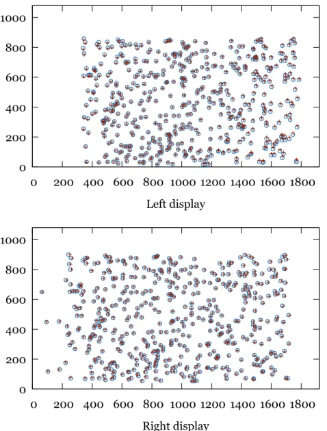
seen in the left and right CC images. . . 47 3.8 A set of 500 random 3D points projected into the displays
by the calibrated view frustums (circles) and as seen by the cameras (crosses) for the left and right sides (top and bottom, respectively) in display pixel coordinates. . . 48 3.9 Variation of horizontal field of view with display Z
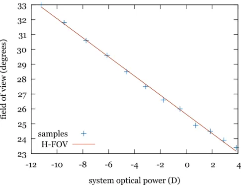
posi-tion (increasing Z means closer to the eye). The display was moved to different positions and FOV measured with the calibration camera. . . 50 3.10 Variation of horizontal field of view with optical power in
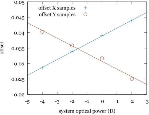
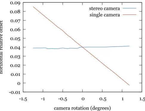
display Z motion version. . . 51 3.11 Relative interdisplay horizontal and vertical offsets (
off-setX andoffsetY, respectively) at different optical powers and approximating functions for one hardware setup. . . 52 3.12 Offsets calibrated by our stereo camera method and by a
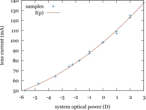
single camera method when the calibrating device chan-ges orientation. The horizontal axis represents an added rotation around the vertical axis of the camera pair or only the left camera in each graph. . . 53 3.13 Curve fit for optical power to display Z position. . . 55 3.14 Curve fit for optical power to current relation. . . 56
4.1 Simulated illustration of the chroma-key concept. Left: a view of the excavator cab with blue covered windows. Right: the view after chroma-key substitution of blue
areas with virtual environment . . . 65
4.2 Architecture for simulator visualization . . . 66
4.3 Left: Excavator cab, Right: Blue box for non vehicle environments . . . 67
4.4 Experimental see-through HMD developed in the project. Two cameras are mounted in front and an active marker for pose tracking is seen at the top. . . 68
4.5 Chroma-key result as presented to the user in the HMD displays. Left: driving an excavator, Right: driving a dumper . . . 70
4.6 Weather radar scan volume. . . 72
4.7 Immersive stereo viewer of weather radar data (ambient light has to be dimmed for a better experience) . . . 74
4.8 Screen view frustum for different users . . . 76
4.9 Ground clutter . . . 78
4.10 The CS-WAVE training welding simulator. . . 80
4.11 Architecture diagram of our experimental welding simu-lator. . . 81
4.12 Hardware for the experimental manual welding simula-tor. The Z800 HMD with a magnetic sensor attached, a hand-held stick with a magnetic sensor (simulating the welding electrode holder) and the magnetic field emitter and control box. . . 82
4.13 Virtual images of the 3D view presented to the user of the welding simulator. . . 84
5.1 Isosurfaces from a radar scan generated with the mar-ching cubes algorithm after cartesian resampling . . . 92
5.2 Illustration of a voxel in spherical coordinates and the
view ray step by step sampling . . . 94
5.3 Texture atlas for radar reflectivity data . . . 95
5.4 Volume render of radar scan (central area) . . . 96
5.5 Interactive 3D building model . . . 100
5.6 Wall isolation layers . . . 101
5.7 Development process . . . 107
5.8 Interactive wind turbine simulation . . . 108
5.9 Data and communications architecture . . . 111
5.10 Product placement interface . . . 113
5.11 Interactive manipulators: translation (left) and rotation (right) . . . 113
5.12 Virtual shop . . . 114
5.13 Heat map of user movements around the environment . . 115
5.14 Visual configuration system architecture . . . 120
5.15 Lift configurator in a Web browser . . . 123
5.16 Recursive mirror reflections . . . 125
5.17 Environment mapping reflection applied to chromed steel handrails and polished steel walls . . . 127
5.18 Real-time subdivision: (left) low polygon count model, (center) online subdivided model, (right) subdivided mo-del with smooth shading . . . 129
3.1 Left and right display FOVs and interdisplay relative off-sets in each hardware setup. The Type column indicates if that hardware uses a tunable lens (L) or display axial motion (D) for accommodation control . . . 49 5.1 3D viewers Web browser plug-ins and their supported 3D
formats and scripting support . . . 105
Introduction
1.1
Introduction
The fields of Computer Graphics and Computer Vision were categori-zed as image synthesis and image analysis [70]. Both fields remained separated for many years. Currently, they tend to support each other as it happens in the Augmented Reality field. Modern categorizations of these fields can be found in the literature (See James D. Foley and Hughes [44], Akenine-M¨oller and Haines [1]).
This thesis compiles research work from 2005 to the present. The research merges contributions from both image synthesis and analysis. However, most of the research can be classified within the classical image synthesis field. This research work will be classified in three areas:
• Stereoscopic viewing in head-mounted displays and their calibra-tion for correct depth percepcalibra-tion, including accommodacalibra-tion.
• Immersive visualization: alternative setups to provide a higher feeling of being immersed in a virtual world.
• Ubiquitous visualization: algorithms and applications of ubiqui-tous interactive 3D visualization where users access remote appli-cations from anywhere with different computing devices.
The following sections describe the thesis goals and the thesis struc-ture.
1.2
Objectives
This thesis pursues the following main goals:
• To research in some problems found in Head-Mounted Displays: automatic calibration and the vergence/accommodation mismatch problems. The thesis should find a calibration method to have non-subjective quantification of stereo perspective pro-jection parameters. This requires to study how virtual 3D space is perceived in Virtual Reality devices, as opposed to how rea-lity is seen, and what can be done to improve this perception. HMDs, by design, present a fixed focus stimulus. However, the stereo stimuli they generate make the eyes converge at different depth distances. This provokes the problem known as vergence-accommodation mismatch. An HMD with controllable variable focus should alleviate this problem. Methods to calibrate such controls are needed to provide correct focus stimuli that match the stereo depth stimuli. This problem affects, to different ex-tents, virtually all kinds of stereo displays.
• To find an adequate immersive solution for different real cases: welding simulator, machinery simulator and volumetric radar data visualization. Vehicle simulators typically simulate a single vehicle type, and only high-end systems include mock-up cabs, seats and controls that feel like the real machines. A more versatile architecture should be designed to allow systems the si-mulation of multiple machines. How Augmented Reality can be leveraged to support this goal had to be investigated. Weather radars collect volumetric information about the atmosphere state
around them. Visualization techniques that can represent this information in the most comprehensible ways had to be analyzed.
• To provide contributions in ubiquitous visualization. A known potential application of Virtual Reality is in transmitting learning concepts. Virtual 3D models should be integrated in systems aimed at learning. Research was needed to apply this concept for ubiquitous learning cases. On the other hand, Vi-sual product configurators let users customize virtual products and see what they will look like when finally manufactured. Their requirement of visual realism is relatively high. Users require an ubiquitous visual product configurator that can work on the Web using advanced render techniques. Finally, the e-commerce sector has grown in presence and acceptance over the years. However, its user interfaces have seen a limited evolution, typically consisting of online catalogs displaying images and descriptions of products. There is a need to research Web3D technology and its limitations, to propose alternative user interfaces based on online Virtual Re-ality paradigms that provide ubiquitous solutions to make them easy to create and use.
1.3
Thesis structure
This thesis is structured in 6 chapters where this introduction is the first chapter.
Chapter 2 introduces a generic background and basic concepts that will be discussed and developed throughout the rest of the document.
The next three chapters contain the main areas of research. Each of them includes specific background and references to the state of the art in its respective area.
Chapter 3 deals with the visual perception of virtual space in HMDs. It explains the issue ofvergence-accommodation mismatch and provides
methods to calibrate the stereoscopic characteristics of HMDs and to control eye accommodation (eye focus) for best viewing.
Chapter 4 provides contributions in immersive virtual reality and Chapter 5 brings contributions in ubiquitous virtual visualization.
Finally, the main thesis conclusions are summarized, followed by possible lines of future work, in Chapter 6.
Background
This chapter provides a generic background on the topics addressed in this thesis.
The three sections in this chapter introduce the core concepts most relevant to Chapters 3 to 5. Section 2.1 introduces the concept of immer-sive VR visualization and the technologies that enable it. Section 2.2 is devoted to general knowledge on the human visual system regar-ding binocular vision and its behaviour with immersive visualization technologies. Finally, Section 2.3 presents the point of view for ubiqui-tous visualization considered in this research. It describes standards and technologies that have been proposed over the years to support it. Using this background, Chapter 5 provides specific contributions to ubiquitous visualization.
2.1
Immersive visualization
Freina and Ott [28] review the state of the art of immersive virtual reality applied to education. In their paper they distinguish between
non- immersive and immersive virtual reality. Following their defini-tion, non-immersive VR is a simulated 3D environment that can be displayed on a standard computer screen, while immersive VR
res special devices to provide a view that surrounds the user, making him/her feel as if standing inside the virtual world. Their review focuses on two types of immersion devices: CAVE and head-mounted display (HMD), which are described in the following subsections. Then, a last subsection adds a description of the most relevant stereo display techno-logies, stereoscopy being a crucial part of any immersive visualization system.
In Leigh et al. [54] a related concept is introduced: tele-immersion. It is defined as “the integration of audio and video conferencing, via image-based modeling, with collaborative virtual reality, in the context of data-mining and significant computation”. Thus, technically, tele-immersion brings together immersive virtual reality in the form of a CAVE, with communication links that support remote multiuser work and tele-presence.
In this thesis the concept of immersive VR used does not necessarily require full 360-degree surrounding imagery. Besides HMDs, we also consider interactive systems with stereo displays of medium to large size with rendering configured to provide a perspective correct view.
2.1.1
Head-mounted displays
The firsthead-mounted display, abbreviated HMD, was created by Ivan Sutherland in 1968 [91]. He had the idea of a display that would present a perspective image that changes as he moves or looks around, just as happens when viewing the real world (see Figure 2.1). An HMD is a portable device attached to a user’s head that presents one or two small displays in front of his eyes. The HMD’s displays show a 3D view of a virtual space in front of the user.
The basic elements of an HMD are a pair of displays and a pair of optics to magnify and focus the displayed images. The displays are often small and placed at a very near distance to the eyes, so optics are used to magnify them and form images at a further virtual distance.
Figure 2.1: Sutherland’s original HMD (left) and the 3D view displayed in it (right), from Sutherland [91]
Additionally, HMDs are usually coupled with tracking systems that determine the user’s head orientation and/or its position and this in-formation is used to render the 3D views from a correct point of view. Sutherland’s original HMD tested two different tracking systems, one based on a mechanical arm with encoders connected to the HMD and one based on ultrasonic transmitters and receivers. Among the charac-teristics of an HMD, the most important visual parameters are:
Field of view (FOV) The apparent size –horizontal, vertical or diagonal– of the images presented, as seen by the user, usually expressed in degrees. A larger FOV enables a higher feeling of immersion.
Resolution The size in pixels of the images displayed to each eye.
Angular resolution The apparent size of each pixel as seen by the user, often expressed in arcminutes or as pixels per degree. This sets a limit to the smallest detail that can be represented and the image sharpness. Let us note that the human visual system’s resolution is around 1 arcmin with a healthy vision.
Since the early 1990s these devices have evolved and spread. In recent years a lot of attention has been put on them focusing on the
consumer market. After a Kickstarter crowdfunding campaign, in 2013 the first prototype of the Oculus Rift [74] was released, an innovative HMD with integrated 3-DoF head tracking (6-DoF in later versions). Unlike traditional HMDs based on separate small microdisplays, the Rift featured a single relatively large display and magnifying optics for each centred on the left and right halves of that screen. This design enabled it to have a much larger field of view, at the expense of a low angular resolution. Inspired on the Oculus Rift success, a few devi-ces were presented by competing companies. HTC released the HTC Vibe, a device similar in design to the Oculus Rift with extended room tracking [39]. Similarly Sony released thePlayStation VRHMD in 2016. Advances in smartphones led to the appearance of very low cost acces-sories with which an HMD can be built. Google Cardboard [60] is a cardboard structure with a pair of lenses, and space for a smartphone. The displays, computation, 3D rendering and orientation tracking are all provided by the inserted smartphone, making it a low cost all- in-one head mounted display.
2.1.2
CAVE Automatic Virtual Environment
In 1992, Cruz-Neira et al. [17] presented the CAVE, a cubic immersive room in which users are surrounded by projected images of a virtual environment. A CAVE typically has semi-transparent walls (and pos-sibly floor and ceiling) and uses rear projection to present computer-generated images on them. The user’s head position and orientation is tracked by some device in order to render the 3D views for each of the walls from the user’s point of view so that he gets a perspective-correct immersive view. Additionally, projection is usually stereoscopic to provide depth-perception.
Figure 2.2 depicts a very simplified view of a CAVE with three active walls. Sometimes, in the place of each shown projector there is a pair of projectors to provide dual-projection for passive stereo visualization.
In practice, CAVEs often place mirrors between projectors and screens to reduce the overall size. This is particularly useful in the projections for the floor and ceiling. With a mirror, the projection axis is bent 90◦ so the projector does not need to be as far from the screen.
Backprojection screens
projector
Figure 2.2: Simplified view of a CAVE system. Actual implemen-tations often use mirrors between projectors and screens to reduce the overall size
The original CAVE, further described by Cruz-Neira et al. [16], had three projection walls plus the floor and used mirrors to reduce size. The floor was front-projected (thus suffering from shadows) also to limit total height. Active stereo with shutter glasses was used (see Section 2.1.3), so one projector per screen was enough. Stereo graphics rendering was performed with two off-axis projections per wall, using the estimated location of each eye inside the cube.
2.1.3
Stereoscopic displays
One of the key features of immersive visualization is stereo projection. The human visual system is binocular and its eyes capture slightly dif-ferent views of the environment in front. This difference provides an
important cue for depth perception and enables humans to perceive a world in three-dimensions. Since display screens are typically flat, they provide an image that is perceived as a flat surface. Stereoscopic or stereo displays implement different techniques to provide stereo vision, that is, to present slightly different images to each eye in order to pro-voke depth perception.
Some stereo displays use separate surfaces for the different images and require optical elements to have the eyes fuse those surfaces into a single image. Other displays present both images on the same surface and require some filter (e.g. in the form of glasses) to have each eye only see one of the images. A good review of the different techniques to provide stereoscopic projection is presented in Mendiburu [66] and more in-depth information regarding their application to stereoscopic 3D cinema can be found in Lipton [56]. Below is a list of the most relevant stereo display technologies:
• The stereoscope: As described by Brewster [8], this device was invented in the 19th century and is comparable in optical design to head-mounted displays but presenting paper photographs instead of video screens.
• Anaglyphs: Anaglyphs present stereo pairs using some colors for one eye and complementary colors for the other eye. The user wears special color filter glasses that let each eye only see one of the subimages. Actually the subimages presented have incomplete color information. For example, red-cyan anaglyphs render the image for the left eye using only its red color channel, and the image for the right eye using only the green and blue channels. A user wears glasses having a red filter on the left eye and a cyan filter on the right eye. This way the left eye sees the red channel of the left image and the right eye sees the green and blue channels of the right view. The brain finally mixes both views into a full color stereo view.
• Shutter glasses: Shutter glasses use time multiplexing to present stereo pairs on the same surface. The left and right views are shown alternatively switching at a high frequency and the user wears special glasses with synchronized shutters that cover the view of each eye when the view for the other eye is being presented. The switching frequency is high enough to prevent the perception of flicker.
• Polarized light: This technique uses light polarization to sepa-rate the left and right subimages. Often two projectors are used, each one projecting the image for one of the eyes, and each one ha-ving a complementary polarizers (linear or circular polarizers are used). Viewers have to wear relatively inexpensive passive polari-zing filter glasses that allow each eye to only see one of the subima-ges. This projection technique requires a polarization-preserving screen so that polarized light projected into them maintains its polarization after being reflected towards viewers. A version of this technique requiring only one projector was also developed. It adds an active polarizer to the projector that switches polarization between succesive frames, which are projected alternating the left and right subimages.
• Interference filters: Interference filters [45] use a more advan-ced form of wavelength multiplexing than anaglyphs. In this case two sets of RGB primary colors are used with slightly offset wave-legths, one set for each eye. Sophisticated filter glasses are worn by viewers to separate the subimages. This technique, introduced by the Infitec company has been successful in 3D cinema under the brand Dolby Digital 3D [30].
• Autostereoscopic screens: The above technologies requires users to wear special filter glasses. Aiming at removing this requirement, some autostereoscopic monitors [21] were presented which could
be viewed with the naked eye. The basic principle of these mo-nitors is the placement of a special occlusion mask or lenticular layer over the screen that allows one eye to only see odd-numbered pixel columns and the other eye to only see even columns. Thus, the stereo pair has to be presented on the screen split in columns: the left view on even columns and the right view on odd columns. These displays are sensitive to observer position and movement from the designed viewing zones will produce incorrect filtering and image ghosting.
• Head-mounted displays: As explained in their own section, head-mounted displays present stereoscopic images by means of two small displays placed in front of the user’s eyes and a pair of lens groups that provide focusing and magnification. The displays containing the lelft and right views appear superimposed in the observer’s field of view.
The enumerated stereoscopy technologies have been used either in cinema to produce 3D films or in other immersive visualization ap-plications, including industrial and leisure uses. In most apap-plications, especially film, the intention is to provide an image withdepth, that is, where some objects are perceived closer than others. In the cases where stereo images are shown on a screen, these objects can appear to be on the screen plane, closer, or further away. But in those applications no special interest is in making objects appear at specific distances or having specific apparent sizes. On the other hand, immersive virtual re-ality applications require virtual objects to appear at correct distances and preserve their sizes in order to provide good immersion.
2.2
Stereo vision and accommodation
Stereo display technologies like those described in the previous section are able to present different images to each of the viewer’s eyes. How exactly the viewer perceives the displayed scene (in terms of depth and 3D shape) depend on how these images differ and how they are looked at. Moreover, when looking at a point in the real world two responses are triggered in the eye related to depth. On the one hand, the eyes converge to align with the target point in a movement called vergence. On the other hand, the eye’s lens changes shape to focus a sharp image of the target object on the retina, a phenomenon called accommoda-tion. An additional response, pupil dilation or contraction will not be taken into account in this work as it is not as relevant to depth percep-tion. A thorough explanation of the structure of the human eye and its behaviour can be found in Gross et al. [36].
Despite their differences, an eye can be compared to a camera having as main elements a variable aperture (the iris), a focusing element (the lens) and an image projection surface (the sensor or the retina). A typical lens is characterized by its focal length (usually expressed in millimeters) or by its reciprocal, the optical power or refractive power
(usually expressed in diopters, 1 D = 1 m−1). Using optical power has the benefit that the power of several consecutive lenses is approximately the sum of their individual powers.
Accommodation is an effect that occurs in each eye even if the other is covered. When looking at a distant object, the eye’s lens is relaxed and its optical power plus the power of the cornea focus its incoming parallel rays into a point on the retina (see Figure 2.3). When looking at a near point, the eye’s lens has to be deformed and thickened to focus rays into a single point. The accommodation optical power required for best focus at each moment is the accommodation demand. The eye’s physiological response is the accommodation, the change in optical power from distant viewing to a shorter distance viewing. It may not be
equal to the demand if this is beyond of the limit of a given eye. This demand can be expressed as an accommodation distance (the distance to the object looked at).
A
A
da lens
∞
Figure 2.3: Schematic view of accommodation: looking at a distant object (top) the lens is relaxed; looking at a near object (bottom) the lens is made thicker to accommodate (focus)
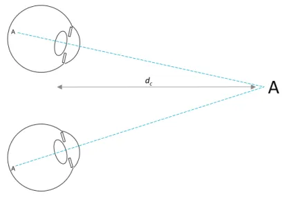
At the same time, when one looks at an object binocularly, the eyes align with it in order to project the target point on the fovea (the central vision point on the retina). This is schematially depicted in Figure 2.4. Typical stereo displays can trigger the eye vergence response given the disparities in the left and right presented images. But, as the display is physically at a fixed distance, blur-induced accommodation demand remains constant. Actually, the control of the vergence and accommo-dation responses are not independent, each controlled by retinal image disparity and sharpness, respectively. There are interdependencies so that image sharpness/blurriness can also affect vergence and stereo
dis-A
AA
dc
Figure 2.4: Schematic view of the convergence needed to fixate an object at a given distane.
parity can affect accommodation. The details of these complex inte-ractions are out of the scope of this thesis. Detailed descriptions of these mechanisms can be found in Schor [82], Templin et al. [93].
Figure 2.5 depicts a pair of eyes watching a stereo screen displaying a small object (letter ‘A’) with positive parallax (the letter appears behind the screen). The viewer’s eyes align with their respective images of the object and thus converge at a point behind the screen. The distance to the screen da is where the eyes should accommodate to have a sharp
vision of the object, and that is different to the convergence distancedc.
However, as Inoue and Ohzu [41] found, the disparity in a stereo screen affects accommodation so that the eyes will try to accommodate at the convergence distancedc. In this situation, the image of the object
will be blurry because the eyes do not focus at the correct distance where the screen is located. The difference betweendaanddccreates a conflict
A
A A dc daA
A
display Apparent position Image for left eye Image for right eyeFigure 2.5: Stereo vision of a stereo display.
known as thevergence-accommodation mismatch.
In the case of viewing a virtual scene in an HMD something similar happens. See Figure 2.6. Here each eye sees a separate screen magnified by optics (one or more lenses), so the distance at which visual axes converge when looking at the displayed letter is not as straightforward to find. The paths these axes follow depend on the position of the displays with respect to the eyes and on the optical power of the lenses. Accommodation distance is also not geometrically obvious. It depends on the optical power of the optics used and the distance between the optics and each screen. This accommodation distance is fixed because those variables (lens optical power and display distances) do not change. The mismatch thus appears in HMDs as well.
A
A A dc A A Left microdisplay Right microdisplay Apparent positionFigure 2.6: Stereo vision in an HMD
2.3
Ubiquitous visualization
Weiser [99] introduced the concept of ubiquitous computing while at Xerox PARC. He envisioned a future where computing was not done directly at workstations but in which computation would unobtrusively surround people. Similar concepts have been proposed, such asambient intelligence or pervasive computing. Our use of the term “ubiquitous” is different. As Chapter 5 will explain, we use the term “ubiquitous visualization” to refer to visualization systems that do not require users to have a complete standalone application and all its data locally instal-led. Instead, ubiquitous visualization systems can be accessed remotely with little specific software on the client side. The term “ubiquitous interactive visualization” was used by Mc Lane et al. [65] in a similar way but with a different technical approach: their system was based on server-side rendering while we intend to leverage 3D graphics
accele-raction on the client side. Web technology has proven to be a platform for ubiquitous delivery and execution of all kinds of applications. Clients only require a computing and display device running a Web browser. The key to ubiquitous interactive 3D visualization is the availability of 3D Web technology or Web3D, i.e. ways to display interactive 3D graphics integrated in Web content.
Web browsers initially supported hypertext-based pages (text con-taining links to other pages). They started to support embedded images with the release of NCSA’s Mosaic browser [2]. Raggett [80] proposed the idea of a markup language for Virtual Reality in the Web called
VRML. A specification of VRML (Virtual Reality Modeling Language) was written by Bell et al. [6], based on SGI’s existing OpenInventor
format. It was followed by a deeply revised version known as VRML97
that was published as an ISO Standard [97]. VRML97 is a format able to specify virtual worlds including geometries, animations, sound, in-teraction and scripts to define behaviour. Later, the X3D (eXtensible 3D [98]) standard was presented as a successor to VRML with extended functionalities and new encodings, including an XML-based notation.
The above formats allowed the description of 3D content in standard declarative ways. Actually embedding 3D content in Web pages requi-red Web browsers to support these formats. This was done indirectly through third-party plugins that extended the browser’s functionali-ties (e.g. CosmoPlayer, ParallelGraphics Cortona, BS Contact). These plugins usually supported only a subset of existing web browsers and operating systems.
In 2006, a new approach to interactive 3D graphics on the Web was proposed. Vladimir Vukicevic presented a demonstration of a Mo-zilla Firefox extension that partially added an OpenGL context for the HTML canvas element (the canvas element already supported a 2D graphics context). The Canvas 3D extension [95], as it was called, ex-posed a subset of theOpenGL ES 1.1 and 2.0 APIs. With this extension,
JavaScript scripts in a Web page could imperatively render 3D graphics using the available hardware acceleration. In the case of the OpenGL ES 2.0 context, rendering is based on programmable vertex and frag-ment shaders. In 2009, Google presented an alternative technology for accelerated graphics on the Web called O3D [77]. Their approach, im-plemented as a browser plugin, was different, based on a scene graph definition, thus allowing higher level programming.
Canvas 3D eventually evolved into WebGL and native support was added to all major Web browsers, on desktop and mobile platforms. It exposes the OpenGL ES 2.0 API to JavaScript in Web pages. Shading in WebGL is specified in programmable shaders written in the GLSL language, bringing a high level of flexibility and allowing complex visual effects. WebGL 1.0 was released as a standard by the Khronos Group [64] in 2011.
WebGL is a relatively low-level API and thus not convenient for many practical applications. To solve this, several JavaScript libraries have been released over the years that expose higher-level interfaces for graphics programming. Examples of these are Three.js [10] and GLGE [9]. Google’s O3D, originally a native plugin, was rewritten as a JavaScript library using WebGL as rendering back end. Another interesting library is X3DOM [5], which partially implements an X3D viewer for WebGL-enabled browsers. This means X3D content can be embedded in Web pages and be visualized on any compliant browser with no need for additional plugins.
Stereo perception and
calibration
3.1
Introduction
Despite increasing sophistication in graphics hardware and software pro-viding a high degree of realism, a number of issues have not yet been solved for Virtual Reality displays. The human visual system provides three-dimensional space perception supported by several cues, i.e. sti-mulus features that give hints about true shape, size and depth. Among them, perspective, binocular disparity, convergence and accommodation are considered to provide the main depth cues. Immersive virtual rea-lity addresses these issues using stereoscopic display devices. The stereo pairs displayed make the user perceive the virtual scene as existing in space. There are two main kinds of stereo displays: head-mounted dis-plays (HMD) and stereo screens. Stereo screens can be monitors or projection screens with some filtering means to have each eye see only one of two images presented on the same surface. This work considers HMDs only.
Stereo displays suffer from an issue known as the vergence-accommo-dation conflict (VAC) [103]. The human vision adapts to the objects of
interest in the real environment in two main ways: eyes rotate in order to orient their visual axes towards the object and they also change focus in order to project sharp pictures on their retinas. These actions are known as vergence and accommodation, respectively. There is a third eye response, the pupil aperture, which will not be considered in this work as it does not affect space perception. In natural binocular vie-wing the two main actions are synchronized: usually the focus distance to an object is the same as the distance at which visual axes intersect. However, in virtual stereoscopy the synchronization is disrupted. Ste-reoscopic systems render objects in a way that stimulates vergence. In this way objects can be perceived either closer or further than the dis-play surface. However, the eyes have to focus at the disdis-play, which is placed at a constant distance. So, there is a conflict between focus and vergence that cause an unnatural view and visual fatigue, especially in near objects. This issue was studied by Hoffman et al. [38].
Stereo HMDs use two separate small screens (often microdisplays) with magnifying optics. When worn on a user’s head the two optics and displays are located in front of each of the user’s eyes. The stereoscopic system renders in each display a slightly different view of the virtual environment that the user perceives as three-dimensional. The distance the eyes have to focus on (accommodation distance) is not just the physical distance to the displays because the microdisplays are behind optics that alter light beams. Moreover, the convergence distance where visual axes meet is not easily identified due to the magnifying effect of the optics.
Rendering images for correct geometric perception has special re-quirements. Steinicke et al. [90] studied how the field of view (FOV) affects perception. They use geometric field of view (GFOV) to denote the FOV used for generating the perspective images, and display field of view (DFOV) to denote the FOV observed, i.e. the angle subtended by the display screen from the viewer’s point of view. The authors state
that a geometrically correct image, as if the screen was a window to the virtual world, occurs when GFOV and DFOV match. So, rendering geometrically correct 3D stereo pairs requires knowledge of the view frustum of the display for each of the eyes.
The problems we have just considered must be taken into account when a stereo system defines the frustums that will be used to render images. When the precise location of all lens elements and microdis-plays are defined with precision, optical display properties can be com-puted by mathematical models of light transport. However, nominal parameters (such as the FOV) provided by HMD manufacturers may have small variations for each device. It has to be noted that the high magnification provided by HMD optics can transform small positioning errors of microdisplays into significant macroscopic effects that inva-lidate nominal values. Several calibration methods for obtaining the view parameters of HMDs have been proposed in the past (see [25], [52], [33]), but they nearly always rely on subjective impressions by the HMD wearer or are only suitable for optical see-through HMDs (see [32], [46]). We believe that users are likely to introduce uncertainties and that user-independent objective methods would help provide more repeatable and reliable information.
In our contribution we argue that to obtain a stereo view with ap-proximately correct depth perception on a specific HMD, its characte-ristics should be measured using objective calibration processes. This means that a physical setup will determine with precision the characte-ristics of a given HMD. Gilson et al. [33] provided an objective approach but has the limitation that is does not explicitly consider the stereo na-ture of the perceived space.
The second contribution of this chapter tackles accommodation de-mand, i.e. the effort requested to the eye to focus at specific distances. In most commercial HMDs the accommodation demand is fixed. Some of them have a manually adjustable focus setting which the user can set
in order to avoid wearing glasses. Then, it remains fixed. As we will see, if this mechanism could be controlled by the VR system we may have a valuable tool that will alleviate the vergence-accommodation conflict. The display system will change focus according to the actual vergence. Kramida and Varshney [50] presented a review of the state of the art on potential solutions to the VAC in HMDs. Within their classification, our system can be described as varifocal.
Our approach requires solving the following problems: (i) computa-tion of the view frustums by calibracomputa-tion of the HMD, (ii) control of the accommodation demand.
We propose a new framework that combines all these ideas for dis-playing images with correctly perceived shape and size in HMD-like ste-reo displays simultaneously stimulating vergence and accommodation. The proposed framework includes calibration methods to objectively measure stereo view frustum parameters that will ensure correct size and distance perception. This work provides users with stereo pairs with convergence and accommodation cues. The current framework does not consider nonlinear image distortion.
The chapter is organized as follows. Section 3.2 deals with objective stereo geometry calibration. Section 3.3 addresses focus control to alle-viate the vergence-accommodation conflict. Section 3.4 discusses expe-rimental results. The chapter finishes with conclusions in Section 6.1. Throughout the text, terms such as focus, accommodation and opti-cal power will be used interchangeably when their meaning is evident. When describing the hardware, the term accommodation will actually refer to accommodation demand, that is, the accommodation optical power requested to the eye in order to see a sharp image.
3.2
Objective stereo display calibration
In 3D computer graphics, images are rendered based on a set of pa-rameters that define the projection characteristics. At least the field of view (FOV) must be defined to control perspective. A small FOV produces a view similar to atele setting in a camera lens, while a large FOV creates a more perspective-distorted view similar to a wide angle
lens. In order to create a faithful view in Virtual Reality the FOV used in rendering must match the field of view that the display appears to have from the point of view of the user wearing the HMD.
When producing stereoscopic projections, additional parameters are used to control the final effect. They should correspond to the viewing conditions. If the stereoscopic projections do not match viewing condi-tions, a different virtual space will be perceived, virtual distances, sizes and shapes will be distorted. These distortions have been studied by Benzeroual et al. [7] (for 3D films) and by Kelly et al. [47] (for VR environments).
In real life, when staring at a point in space, the eyes rotate such that their visual axes intersect at that point. The distance to this intersection point, the convergence distance, is the distance at which we perceive the point to be. When looking at a very distant object, visual axes remain approximately parallel. A correct stereoscopic perspective projection should have the same properties.
Modelling visual axes and their intersection in a stereoscopic screen
only requires knowing the position of the user in front of the screen, the user’s interpupillary distance and the screen dimensions. For more precision, the user’s head orientation can be used to find the location of each eye relative to the screen.
In the case of a head-mounted display the situation becomes more complicated due to the fact that the left and right images use sepa-rate microdisplays which are seen through sepasepa-rate optics. The lenses of the HMD distort and magnify the image of the microdisplays. The
dimensions and precise position of the microdisplays are also distorted and magnified. So, small positioning errors of each display may lead to significant misalignments affecting the stereoscopically perceived geome-try. Horizontal misalignment alters depth perception as the vergences will be altered leading to a different convergence distance. And vertical misalignment may lead to double vision and no depth perception at all: the eyes can only fuse if left and right corresponding stimuli are within a small angular elevation difference. This is known as Vertical Disparity Amplitude tolerance (see Fukuda et al. [31] and Di et al. [20]).
Most VR rendering systems assume that the microdisplays of an HMD are centred in front of each of the user’s eyes. So, the projection matrices that generate the images on the HMD are known to be sym-metric perspective projection matrices.
However, usually the microdisplays have small offsets (see Figure 3.1). Even HMDs of the same model can have different offsets. In order to deliver a correct view in the HMD, the VR rendering system must know these offsets to compute the correct projection matrices. So, we need a simple, precise and objective calibration method that finds these data for each HMD. Figure 3.1 shows the correct view frustums that must be found.
Several calibration procedures have been proposed for different ste-reoscopic displays. For CAVE-like setups Ponto et al. [78] introduced a perceptual calibration procedure. The calibration of see-through HMDs has been addressed by many authors, such as Figl et al. [25], Figl et al. [26], Gilson et al. [32], Kellner et al. [46], Makibuchi et al. [61], Itoh and Klinker [42]. Indeed, correct projection in those devices used in augmented reality is crucial or otherwise virtual and real objects will appear misaligned. These methods take advantage of the see-through nature of those devices and require users to look at physical targets pla-ced in front of the HMD. They are thus not usable in immersive HMDs (i.e. non-see-through) in which there is no view of the real world. In
right eye left eye FOVL offset XR offset YR X XL XR
Figure 3.1: View of the display from each eye. Each display is offset with respect to the perfectly centred position. Thus, in order to represent a point that is perceived at position X, its left and right positions xL,
xR have to be drawn at vertically and horizontally offset positions in
each display.
immersive HMDs the lack of real references makes projection errors less noticeable but still a correct geometric perception requires correct projection parameters. In this case applications usually either use the device’s nominal parameters or employ subjective calibration methods, such as Kuhl et al. [51], because of the lack of externally observable features (only the wearer sees the HMD’s displays).
In contrast, Gilson et al. [33] proposed a method for objective cali-bration of immersive HMDs that uses one camera placed in the position of the user’s eye. It is an evolution of their earlier method for see-through HMDs (Gilson et al. [32]). The camera captures a pattern presented in the HMD display. From analysis of the captured pattern,
they compute a mapping between the camera image and the HMD dis-play coordinates. Then the HMD is removed while keeping the camera still and a marker is placed in the space in front. The marker is tracked with an external tracking system while it moves in the space in front of the camera. By relating the projection of the marker in the camera image, its tracked position in space and the position of the displayed pattern in the same image, the method computes the theoretical pro-jection matrix of one display of the HMD. It then proceeds with the other display to create a stereo projection pair.
We see several limitations in this approach. First, it requires a com-plex setup including an external high-end position tracking system and a precise positioning of the camera with respect to the HMD. Then, the method calibrates the left and right displays in sequence. Stereo depth perception depends on the relation between the apparent posi-tion of points in each display. Then, such a sequential calibraposi-tion can easily distort depth percepts. The authors acknowledge that a slight modification in camera position with respect to the HMD results in a different computed view frustum. Thus, the unintended different posi-tion or orientaposi-tion of the camera in front of each of the displays will lead to shifted visual axes and modified stereo distances.
The following subsection describes our proposed calibration method to obtain the parameters that allow the stereo system to compute view frustums for acceptable depth percepts.
3.2.1
New stereo view calibration procedure
Our approach shares some concepts with the one proposed by Gilson et al. but does not require an external tracking system and eliminates the uncertainty in position of the camera with respect to each of the dis-plays, among other differences. We propose the use of a pair of rigidly attached cameras to simulate the user’s eyes (calibration cameras or CC in Figure 3.2). This pair gets a view of the virtual space projected by
the rendering system as perceived by a user. The camera pair is previ-ously calibrated, intrinsically (each camera) and extrinsically (the right camera with respect to the left). This is computed from a set of images of a calibration pattern (a chessboard) in different positions taken with the camera pair (see Figure 3.3). This calibration step is performed only once for our CCs and is used later on for the calibration of any HMD. Its results are the matrices of intrinsic parameters (KL,KR) and
extrinsic parameters (RR,tR) that will be later referenced in Equation
(3.1). left HMD display right CC left CC X right HMD display image viewed by left CC image viewed by right CC xL xR x y z
Figure 3.2: HMD stereo projections calibration. A pair of rigidly atta-ched CC (calibration cameras) substitute the eyes. The HMD displays’ misalignment is exaggerated in the illustration.
We have defined a simplified projection model. The rendering mo-dule of the VR system will use view frustums defined by 6 parameters. The projection model is defined by two virtual cameras separated by the
Figure 3.3: A subset of the stereo images used for calibrating the ca-mera pair (left caca-mera and right caca-mera).
interpupillary distance. These virtual cameras have their principal axes parallel. Ourview frustum pair (VFP) parameters are the following:
• Interpupillary distance or IPD. This is the separation between the two eye centres. Will be set to a fixed typical value.
• Displays aspect ratio. This is the ratio of width to height of the microdisplays.
• Horizontal FOV angle of the left and right displays. Note that these can be different, as we will see.
• Horizontal and vertical offsets between the displays. These para-meters describe the relative displacement in both axes between the view of the microdisplays with respect to a perfectly centred
position in front of each eye. They are measured with respect to display size so that, for example, a vertical value of 0.5 would mean the right display appears shifted vertically a length equal to half the screen height.
This model does not define separate offsets for each display but a relative displacement between them. This enables a much simpler operation and still ensures depth perception.
Interpupillary distance and display aspect ratio are known in ad-vance. However, FOV and offsets can vary for each specific HMD. These parameters must be known by the rendering module in the VR system in order to create correct virtual world projections. The calibration process we propose measures these parameters in a specific HMD. Even HMDs of the same model may have slightly different values. This fact shows the importance of using a simple and precise HMD calibration system.
Our calibration process is based on the projection of an arbitrary point in 3D space onto two different image planes, each with its own coordinate system: the HMD displays coordinate systems and the ca-libration cameras coordinate systems. In the equations in this section
xcam will denote points projected on a CC image, and xdisp will
de-note points projected on an HMD display. Both are in homogeneous coordinates, as they are used in projective geometry equations.
a) CC image coordinate system
Given a point X in 3D space and knowing the CC parameters, its pro-jection on each CC image coordinate system is determined by Equation 3.1.
We have a pair of cameras, so there are actually two sets of pa-rameters: KL, KR, RL, tL, RR, tR. In our case, since our extrinsic
parameters take the left camera as reference, RL is an identity matrix
andtL is a null vector. KL,KR,RR and tR are computed once for the
CC pair and remain constant for the calibration of any HMD.
b) Display coordinate system
On the other hand, in the VR rendering system, the view frustum for each eye can be defined by a projection matrix P. For this matrix we have chosen the form typically used in computer vision, as expressed in Equation 3.2. P= fx 0 cx 0 fy cy 0 0 1 (3.2)
This matrix should be derived from the 6 model parameters we have defined. However, we do not know their values until the HMD calibra-tion process is completed.
Each eye sees the virtual world from a different point of view. There is no rotation (i.e. the rotation matrix is an identity matrix) because we have defined our virtual cameras to be parallel and aligned with the CC
Z axis. Combining projection matrix and point of view, the projection of a pointXin 3D space by the rendering system into one of the displays is expressed by Equation 3.3.
xdisp =P[I3|t]X (3.3)
Again there are actually two matrices, PL and PR and two
transla-tion vectorstLandtRfor the left and right displays, respectively. These
subscripts will be omitted for clarity throughout this section when the specific side is irrelevant as both are processed the same way. As the
equation expresses, there is no rotation as both virtual cameras have their principal axis parallel to theZ axis. And, as before, the reference system is the left eye, so tL is a null vector and tR is (−IPD,0,0). PL
and PR are the unknowns that will be computed by the calibration
process.
c) Mapping between display and CCimage coordinates
For each of the left and right sides, any virtual 3D point X is pro-jected onto a point xdisp in the display coordinate system as expressed
in Equation 3.3. The same 3D point is projected onto a point xcam
in the camera image coordinate system, as expressed in Equation 3.1. These two projected points have to be equivalent but they are in dif-ferent coordinate systems so their equations cannot be combined. A mapping between these two coordinate systems is needed to solve the problem. In a low distortion environment this mapping can be approx-imated by a 3×3 transform matrix M in homogenous coordinates (i.e. a homography) as shown in (Equation 3.4).
xdisp =Mxcam (3.4) Now we explain how this mappingMcan be estimated. The camera images contain a view of the microdisplays (see Figure 3.2). By finding a set of corresponding points in both display coordinates and CC image coordinates, the transformation M can be approximated. At least 4 point correspondences are needed. Actually, since the displays are usu-ally nearly perpendicular to the camera view orientation, the mapping is approximately equivalent to an affine transformation. In that case the minimum requirement can be simplified to 3 point correspondences and the bottom row of M would be [0,0,1].
d) Computing the mapping
Our proposed calibration procedure employs an interactive process to determine this mapping. A fixed grid pattern is presented on both dis-plays and a pair of images is grabbed with the CC cameras. Then these images are presented to a user who has to click on at least 4 specific pattern points with the mouse. We know the display coordinates of the points, as we have rendered them, and the user marks their corre-sponding camera image coordinates. From these point correspondences between display coordinates and camera image coordinates the algo-rithm computes the transform matrix M that relates the two images (display and camera).
e) Finding the projection parameters
Once the mapping M is known, we can find the elements of matrix P
by minimization of the reprojection error as defined by the following expression. minX i p(x cam i )−p(Mx disp i ) (3.5)
where xi for i = 1...N are the projections of a set of arbitrary virtual
3D points Xi and p(x) is given by Equation 3.6:
p(x) =p([x, y, z]T) = " x/z y/z # (3.6)
Substituting the expressions from Equations 3.1 and 3.3 Equation 3.5 expands to:
minX
i
kp(K[R|t]Xi)−p(MP[I3|t]Xi)k (3.7)
where the only unknowns are the 4 unknown elements of matrix P, the rendering projection matrix. The Levenberg-Marquardt algorithm
[62] is applied to solve the minimization problem and estimate the 4 unknowns.
In each iteration the algorithm uses a set of N random points in the space in front of the viewer and visible by both eyes and projects them with the current value of the projection parameters. Their projection in display coordinates is transformed to camera coordinates using the computed mappingMand the distance to their projection by the came-ras in pixels is used as reprojection error. The projection is initialized with a fixed set of parameters corresponding to the HMD’s nominal perspective projection with no offsets or a standard guess if there is no such information. The Levenberg-Marquardt algorithm finds the pro-jection matrix elements fx, fy, cx, cy that minimize reprojection error
for each display. The process is executed for the left and right displays separately.
3.2.2
Extraction of projection parameters
The algorithm in the previous section computes a projection matrix P
for each display. That should be sufficient as such a matrix can be converted into, for example, an OpenGL projection matrix ready for rendering graphics. But our rendering system does not use these pro-jection matrices directly for several reasons. As the following sections will show, the projection characteristics are not fixed, but vary when varying optical power (i.e. setting different accommodation distances). For this reason the rendering engine has to continually adjust projecti-ons by interpolating values obtained in different conditiprojecti-ons of optical power.
The computed projection matrices are affected by the orientation of the cameras with respect to the HMD. This means that the projections obtained for different optical powers will have unintended variations if the cameras are not always positioned with the exact same pose.
This is why we prefer to compute a relative, inter-display offset that is unaffected by small camera deviations.
Instead of the raw projection matrices our VR system uses the 6 parameters described at the beginning of Section 3.2.1 to recreate new projection matrices for rendering. The first two parameters ( Interpu-pillary distance and display aspect ratio are known in advance. The remaining 4 (left and right FOVs and horizontal and vertical interdis-play offsets) are extracted from the elements of matrix Pas follows.
The horizontal and vertical FOVs are related to the fx and fy
ele-ments. They can be extracted from the computed projection matrix as shown in Equations 3.8 and 3.9, where w and h are the width and height in pixels of the displays.
FOVH = 2 arctan w 2fx (3.8) FOVV = 2 arctan h 2fy (3.9) And the relative offsets are related to the principal point parameters
cx and cy. They are the difference of these parameters between the left
and right projections, divided by display resolution in order to make them resolution independent (Equations 3.10 and 3.11). The subscripts
LandR denote the parameters for the left and right sides, respectively, which are separately obtained.
offsetx = cxL−cxR w (3.10) offsety =− cyL−cyR h (3.11)
The rendering engine uses the field of view value to compute a stan-dard OpenGL projection matrix, and then modifies this matrix with added horizontal and vertical offsets. As we have relative offsets
bet-ween displays, we apply half of each offset to the left image and half to the right image with opposite signs.
Actually, the cameras can have some optical distortion and a set of distortion coefficients are obtained as part of the camera calibration. The above camera projection equations, such as Equation 3.1 do not show this effect for simplicity but it is taken into account. We apply these distortions when computing the cost function in the minimization process.
3.3
Accommodation control
As stated in the introduction, the vergence-accommodation conflict ari-ses due to the fixed accommodation demand created by conventional stereoscopic displays, including HMDs. We intend to alleviate this is-sue by providing variable accommodation demand. The goal is to vary accommodation distance in order to match the convergence distance continuously. As we will see, an additional problem is to know the actual user’s convergence distance.
The idea is to be able to modify a physical variable which makes accommodation vary. Then, the relation between this variable and ac-commodation must be known in order to set the desired acac-commodation from the computer.
Fischer et al. [27] proposed eight theoretically feasible methods to achieve variable accommodation in HMDs. Out of them we have imple-mented and tried the following two as they seem the simplest and most feasible in practice.
1. Translation of the display: motion of the microdisplays along the optical axis by means of a precision actuator modifies their percei-ved optical power (Figure 3.4). A closer accommodation demand is achieved by approaching the display to the eye.
2. Use of a liquid-filled lens: One of the lenses in the optical path is an electro-optical lens, i.e. a liquid-filled lens that modifies its shape and focal length as a function of an applied electrical current (Figure 3.6).
Most of the other methods in Fischer’s enumeration require too com-plex components, such as aspherical elements, multifocal lenses, liquid crystals or adaptive optics, and are harder to control. One of the other methods, the translation of the lens assembly, is similar to the transla-tion of the display (they both modify the distance between the lenses and the microdisplays). This method has the disadvantage that vignet-ting and image clipping may appear as the lenses move. On the other hand, the survey presented by Kramida and Varshney in [50] mentions liquid lenses and translating lenses (calledsliding optics in their paper), but not translating displays.
We will first explain the use and calibration of the first type of design, which is schematically depicted in Figure 3.4. In this case, the microdisplay for each eye can be moved back and forth along the Z axis with submillimetre precision. Each display position along this axis corresponds to one accommodation value.
eye
eyepiece fixed optics microdisplay on motorized base
z
Figure 3.4: Simplified schematic diagram of variable focus design based on movable display on a motorized base.
Instead of directly controlling accommodation distance, we will con-trol its reciprocal, the accommodation optical power expressed in diop-ters, which is more convenient (1 D = 1 m−1). We define the system optical power as the optical power perceived by the user and that his/her eyes have to accommodate (i.e. accommodation demand). When look-ing at a distant point, the system optical power is zero, i.e. there is no accommodation demand. A near object located at a distance d cor-responds to a negative optical power −1/d forcing the eye to apply a positive accommodation power 1/d to compensate. System optical power is:
p=−1
d (3.12)
where d is the distance of the displayed object.
In order to set optical power to a desired value there must be a known relation between action and effect: how optical power varies as a function of display position. One way to establish this relation would be to accurately model the theoretical optical system and determine it mathematically. Another way is to obtain the relations experimentally. We propose a calibration method to obtain this relation without detailed knowledge of the optical design.
3.3.1
Movable display calibration
The basic idea of our method is to measure several pairs of values (dis-play position and its corresponding optical power) and fit parametric curves to them. These functions will be used by the computer to set the desired accommodation.
Our calibration procedure for each of the visors in the hardware with moving displays is as follows:
1. The camera focused at infinity looks at the display through the eyepiece.